HP ProLiant GbE2 User manual
- Category
- Network switches
- Type
- User manual
This manual is also suitable for

ProLiant BL p-Class GbE2 Interconnect Switch Overview
white paper
Abstract.............................................................................................................................................. 3
Introduction......................................................................................................................................... 3
GbE2 Interconnect Kit .......................................................................................................................... 4
Modular hot-swappable design.......................................................................................................... 4
Support for copper and fiber-based networks ...................................................................................... 4
Interconnect switch architecture ............................................................................................................. 4
Downlink ports................................................................................................................................. 5
LAN interconnect module uplink ports................................................................................................. 6
Front panel ports.............................................................................................................................. 6
10-Gb fabric ................................................................................................................................... 6
Crosslink ports................................................................................................................................. 7
Maximizing network cable reduction ..................................................................................................... 7
Network load balancing....................................................................................................................... 8
Investment protection............................................................................................................................ 8
Fibre Channel pass-through................................................................................................................... 9
Switch management........................................................................................................................... 11
Rapid deployment, back-up, and restore........................................................................................... 11
IP addressing................................................................................................................................. 12
Web browser-based interface.......................................................................................................... 12
Scriptable command line interface ................................................................................................... 13
Simple network management protocol..............................................................................................13
Switch security............................................................................................................................... 13
Serviceability and diagnostics ......................................................................................................... 14
Virtual LAN ................................................................................................................................... 16
Spanning tree................................................................................................................................ 16
EtherChannel compatible link aggregation........................................................................................16

Enterprise-class performance............................................................................................................... 16
Network adapter teaming................................................................................................................... 16
Conclusion........................................................................................................................................ 17
Appendix: Summary of features of the ProLiant BL p-Class GbE2 Interconnect Kit....................................... 18
Switch performance........................................................................................................................ 18
Switch network features .................................................................................................................. 18
Switch deployment and configuration............................................................................................... 18
Switch diagnostics and monitoring................................................................................................... 19
Switch security............................................................................................................................... 20
Switch availability.......................................................................................................................... 20
Switch investment protection............................................................................................................ 20
Switch ports per server blade enclosure............................................................................................ 21
Switch physical and environmental................................................................................................... 21
For more information.......................................................................................................................... 22

3
Abstract
This white paper provides an overview of the second generation Gigabit Ethernet (GbE2) Interconnect
Kit options for the ProLiant BL p-Class system. Each GbE2 Interconnect Kit includes a pair of industry-
standard Ethernet switches that dramatically reduce the number of Ethernet network cables attached to
the rear of the ProLiant BL p-Class server blade enclosure. When the GbE2 Interconnect Kit is used
with the optional GbE2 Storage Connectivity Kit, it also provides pass-through of Fibre Channel
signals from the ProLiant BL20p G2 server blade.
The intended audience for this paper includes engineers and system administrators familiar with the
overall network design of the ProLiant BL p-Class system. For readers not familiar with this overall
network design, please see the ProLiant BL p-Class Networking Overview
1
white paper.
Introduction
The HP ProLiant BL p-Class system includes a portfolio of ProLiant BL p-Class server blades, the p-Class
server blade enclosure, and four interconnect options.
The ProLiant BL p-Class server blade family includes the dual-processor ProLiant BL20p and BL20p G2
server blades for mid-tier applications and the quad-processor BL40p server blade for back-end
applications.
The 6U (10.5 inch) p-Class server blade enclosure has eight server bays, and two outermost
interconnect bays for collection of the network and storage signals. The signals are routed from the
server blades, across the server blade enclosure backplane, and to the interconnect blades.
HP offers a family of interconnect options so that customers can choose how the Ethernet network
signals exit the server blade enclosure. Interconnect options include two patch panel pass-through kits
and two integrated Ethernet switch kits (the GbE Interconnect Kit and the GbE2 Interconnect Kit). The
two patch panel options allow all Ethernet network signals to pass through to third-party LAN devices,
thus giving customers flexibility in choosing their own switches. The GbE and GbE2 Interconnect Kit
options include managed Ethernet switching technology that provides up to a 32-to-1 reduction in
network cables at the back of the BL p-Class enclosure. This cable reduction significantly reduces the
time required to deploy, manage, and service ProLiant BL p-Class systems.
Please see the ProLiant BL p-Class Networking Overview white paper for a summary of all four
interconnect options along with an interconnect decision chart to assist in choosing the appropriate
type of interconnect switch to use.
This white paper describes the GbE2 Interconnect Switch. The GbE2 Interconnect Switch is intended
for applications that require up to 1000 megabits per second (Mb/s) Gigabit Ethernet network
adapter (NIC) consolidation, advanced network feature support (including a future option for layer 7
switching), ProLiant BL20p G2 Fibre Channel pass-through, and future upgradeability for 10 Gigabit
Ethernet bandwidth connectivity to the network.
1
Available at http://h18004.www1.hp.com/products/servers/proliant-bl/p-class/bl-p-interconnect-switch2.html.

4
GbE2 Interconnect Kit
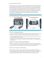
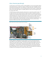
The GbE2 Interconnect Kit contains two redundant, hot-swappable GbE2 Interconnect Switches and
two 4-port LAN interconnect modules. Users first insert the LAN interconnect modules into the bottom-
left and bottom-right interconnect bays at the rear of the server blade enclosure and then install the
interconnect switches into the interconnect bays from the front of the enclosure (Figure 1). The GbE2
Interconnect Switches consolidate the 32 Ethernet ports from the server blades into one to twelve
external Gigabit Ethernet ports: eight ports on the two LAN interconnect modules and four additional
ports on the front of the switches. If desired, users can configure the GbE2 Interconnect Kit to
concentrate the 32 Ethernet signals into a single external Ethernet port (see the section titled
"Maximizing network cable reduction").
Figure 1. Installation of LAN interconnect modules and GbE2 Interconnect Switches
Modular hot-swappable design
To enhance the system serviceability and simply upgrades, both the GE2 Interconnect Switch and the
LAN interconnect modules are hot swappable. This modular design provides two key benefits:
• The GbE2 Interconnect Switches can be quickly and easily removed and replaced from the front of
the rack without the need for re-cabling.
• Each GbE 2 Interconnect Switch can support copper or fiber Ethernet network uplinks by using
different LAN interconnect modules. This design also allows the uplinks to be easily upgraded to 10
Gigabit Ethernet.
Support for copper and fiber-based networks
Two interconnect kit options are available: the C-GbE2 Interconnect Kit for copper-based networks
and the F-GbE2 Interconnect Kit for fiber-based networks. These kits are identical with exception of the
interconnect modules, which are described in the "Interconnect switch architecture" section.
Interconnect switch architecture
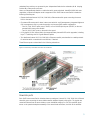
Each GbE2 Interconnect Kit provides an end-to-end, fully redundant architecture that maximizes
network availability (Figure 2). Redundant network adapters are routed from each server blade bay to
each hot-swappable interconnect switch (four NICs total per server bay) creating a fully meshed
topology to the external Ethernet network. The interconnect switches are cooled by on-board

5
redundant fans and they are powered by two independent feeds via the redundant, N+N hot-plug
ProLiant BL p-Class power enclosure.
Users can independently disable or enable the switch ports as desired. Auto-MDI/MDIX with auto-
negotiation of speed and duplex mode is supported. Each GbE2 Interconnect Switch includes the
following Ethernet ports:
• Sixteen dedicated internal 10/100/1000 Mb/s Ethernet downlink ports connecting the server
NICs to the switch.
• Six external Ethernet ports for data, interconnect switch A and B management, Integrated Lights-out
(iLO) management, and/or pre-boot execution environment (PXE) remote configuration.
– Four 10/100/1000T uplink ports (C-GbE2) or four 1000SX uplink ports (F-GbE2) on the rear-
mounted LAN interconnect module.
– Two 10/100/1000T ports on the switch front panel.
• A 10-gigabit (10-Gb) internal fabric that supports future planned GbE2 switch upgrades, including
layer 3-7 switching and 10 Gigabit Ethernet uplinks.
• Two dedicated internal 10/100/1000 Mb/s Ethernet crosslink ports bundled as a multi-port trunk
for switch-to-switch communication and failover, if desired.
These Ethernet ports are described in the following subsections.
Figure 2. ProLiant BL p-Class GbE2 Interconnect Kit architecture
Downlink ports
Each GbE2 Interconnect Switch includes sixteen pre-assigned, internal 10/100/1000 Mb/s Ethernet
downlink ports connecting the server blade network adapters signals to the switch. The signals are
routed as Ethernet from the server blades, across individual category 5e (CAT5e) specified signal
traces on the passive backplane assembly of the server blade enclosure, and then to the switches.

6
LAN interconnect module uplink ports
The LAN interconnect module uplink ports are typically used to connect the interconnect switches to
the network infrastructure; however, they are standard Ethernet switch ports and may be used as
desired. The GbE2 interconnect kits are identical with exception of the LAN interconnect modules. The
C-GbE2 Interconnect kit includes two QuadT2 interconnect modules, each with four 10/100/1000T
Ethernet ports with RJ-45 connectors. The F-GbE2 Interconnect Kit includes two QuadSX interconnect
modules, each with four 1000SX Ethernet ports with LC connectors. Each interconnect module has an
independent guide pin to ensure insertion alignment and a robust connector assembly to prevent it
from being used with incompatible devices.
Table 1. Interconnect modules used with the C-GbE2 and F-GbE2 Interconnect Kits
Components C-GbE2 Interconnect Kit F-GbE2 Interconnect Kit
Interconnect switches Two GbE2 Interconnect Switches Two GbE2 Interconnect Switches
Interconnect modules Two QuadT2 interconnect modules with:
• Four 10/100/1000 BASE-T/TX/T ports
• Four RJ-45 connectors with link speed
and activity LEDs.
Two QuadSX interconnect modules with:
• Four 1000 BASE-SX ports
• Four LC connectors with link speed
and activity LEDs
Front panel ports
Two 10/100/1000T external ports are conveniently located on the front panel. These front panel
ports allow users to perform local management and diagnostic tasks without unplugging a dedicated
uplink. This prevents disruption the production network to perform these tasks. See the “Serviceability
and diagnostics” section for more details on the switch front panel.
When the front panel ports are not used for local management, one or both ports may be used as
additional uplinks. A channel is provided at bottom of each interconnect switch to allow network
cables to be routed from the front to the rear of the rack, or vice versa.
10-Gb fabric
The GbE2 Interconnect Switch offers maximum flexibility and investment protection supporting
enterprise networking requirements today and in the future. Each GbE2 Interconnect Switch includes a
10-Gb (10,000 Mb/s) internal fabric. This fabric is based on the Broadcom HiGig™ technology for
sophisticated chip-to-chip interconnection enabling intelligent packet switching at 20 Gb/s data
bandwidth full duplex.
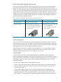
The 10-Gb fabric supports future planned upgrades including:
• A layer 7 option that provides network routing and IP load balancing content delivery switching.
The 10-Gb fabric for each switch includes an internal card slot that supports an optional layer 7
mezzanine card (Figure 3).
• A 10-Gb Ethernet uplink upgrade, which is ideal for bandwidth-intensive applications and
convergence of IP-based network and storage systems. Users can add a 10-Gb Ethernet switch
mezzanine card to each GbE2 interconnect switch via a second option card slot in the 10-Gb
fabric (Figure 3). The existing Gb LAN interconnect modules are replaced with new interconnect

7
module that contain a 10-Gb Ethernet high-bandwidth uplink. The 10-Gb LAN interconnect modules
may also contain Gigabit Ethernet ports, if space permits.
With these future planned options for the GbE2 Interconnect Switch, an administrator will be able to
independently select the switching layer as well as the uplink bandwidth, all within a single switch.
Both options can be installed by users in the field without powering down the server blades or the
server blade enclosure. Availability of these options will be announced in the near future.
Figure 3. ProLiant BL p-Class GbE2 Interconnect Switch 10 gigabit fabric
Crosslink ports
The two GbE2 Interconnect Switches are connected through a pair of redundant, 10/100/1000
Mb/s Gigabit Ethernet crosslink connections that are bundled in a 2000 Mb/s Cisco EtherChannel
compatible multi-port trunk. The signals are routed as Ethernet from switch to switch via individual
CAT5e specified signal traces on the passive backplane assembly of the server blade enclosure. The
crosslinks permit communication between the switches, if desired. They also provide the ability to:
• Manage both switches, perform PXE server boots, and access all iLO interfaces using any number
of external switch ports. Therefore, a single switch uplink can be used to perform all Ethernet
management tasks.
• Configure the p-Class system for advanced ProLiant Network Adapter Teaming including switch
fault tolerance. See the section “ProLiant Network Adapter Teaming” for additional information.
• Communicate with any server network adapter from any switch uplink port. As a result, any single
uplink port may be used to communicate to all 32 NICs. This permits the 32-to-1 cable reduction
and provides additional system redundancy. If uplinks on one switch or the connection to a switch
were to fail, all NICs still can be accessed via the other switch.
Maximizing network cable reduction
For maximum (97 percent) cable reduction, the 32 Ethernet signals within the server blade enclosure
can be concentrated into any one external Ethernet port. This results in a total of six Ethernet
connections for a fully configured 42U rack of six server blade enclosures containing 192 network
adapters.

8
Applications that utilize a single uplink port include testing and evaluation systems, server blade
enclosures with a few installed servers, and applications that require minimal bandwidth. On a
heavily utilized system, using a single uplink port for all 32 network adapters can cause a traffic
bottleneck. For example, using one uplink from interconnect switch A requires the traffic from all the
network adapters routed to switch B to travel over the two crosslinks (a 2000 Mb/s path), previously
shown in Figure 2. The crosslinks are intended primarily as a failover route and generally are not
used as a primary path. For more optimal performance, at least one uplink port on each interconnect
switch would be used. However, system administrators may use any combination from one to all
twelve external Ethernet ports to increase bandwidth, to separate network and management data onto
physically isolated ports, or to add redundant connections to the Ethernet network backbone.
Another means to achieve network cable reduction is to link the GbE2 Interconnect Switches with
other ProLiant BL e-Class and p-Class interconnect switches from different server blade enclosures. This
is ideal for customers with multiple blade enclosures within a rack. It also allows the network
administrator to define the desired level of network blocking or oversubscription.
Network load balancing
ProLiant BL systems configured with the interconnect switch support three network load balancing
solutions. Options exist for providing this functionality integrated within or exterior to the server blade
enclosure.
For load balancing within the server blade enclosure, the p-Class GbE2 Interconnect Kit future layer 3-
7 upgrade (discussed in the section titled "10-Gb fabric”) or the currently available F5 Network BIG-IP
Blade Controller (BIG-IP) may be used. BIG-IP is a software option for ProLiant BL e-Class and p-Class
systems that provides a very economical solution to load balancing and traffic management between
multiple server blades that reside in a single to multiple server blade enclosures.
BIG-IP is available from F5 Networks as a software option installed on ProLiant server blades. One
license is installed on a server making the server blade into a “dedicated” load balancer; no
additional software can be installed on the server blade. For a redundant solution, two copies of BIG-
IP are installed on two server blades. The server blade(s) with BIG-IP installed may perform load
balancing on blade servers that reside in the same or different server blade enclosures, both e-Class
and p-Class. The blade servers may be located anywhere on the network as long as load balanced
traffic to and from the servers pass through the BIG-IP Blade Controller. For more information on BIG-
IP Blade Controller for ProLiant BL systems, see http://h71028.www7.hp.com/enterprise/html/4557-
0-0-0-121.html.
For load balancing exterior to the server blade enclosure, a third party layer 7 Ethernet switch or
network load balancing appliance may be used. This traditional approach uses a multi-tiered
architecture where the interconnect switches are connected to one or more layer 7 switches or
network load balancing appliances. Layer 7 switches and network load balancing appliances are
available from several network vendors including Cisco, F5, Nortel, and others. This solution is
supported on both e-Class and p-Class configured with any interconnect kit.
Investment protection
The GbE2 Interconnect Kits are fully supported in the p-Class sever blade enclosure with any
combination of ProLiant BL20p, BL20p G2, and BL40p server blades.
Users can upgrade to the GbE2 Interconnect Kit from existing RJ-45 Patch Panel, RJ-45 Patch Panel 2,
and GbE Interconnect Kits without powering down the server blade enclosure or server blades. If
users upgrade from the GbE Interconnect Kit, one GbE Interconnect Switch may be replaced at a time
while the other switch remains operational. This allows critical network resources to be transferred
from one switch to the other.

9
Fibre Channel pass-through
The GbE2 Interconnect Kits offer the ability to pass-through BL20p G2 Fibre Channel signals using the
optional GbE2 Storage Connectivity Kit. Therefore, both Ethernet LAN signal consolidation and Fibre
Channel SAN signal pass-through is now possible with a single interconnect. The GbE2 Interconnect
Switch chassis is simply used as a carrier to pass-through the Fibre Channel signals. The Ethernet LAN
and the Fibre Channel SAN signals are completely isolated from each other even though they share
the common GbE2 chassis.
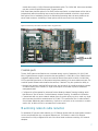
The GbE2 Storage Connectivity Kit provides components for one p-Class server blade enclosure. This
kit contains two GbE2 Fibre Channel Mezzanine Cards (one per switch) consisting of a retimer to
recondition the Fibre Channel signals and two 8-port SAN (OctalFC) interconnect modules (Figure 4).
Customers plug the GbE2 Fibre Channel Mezzanine Card into the connectors provided in each GbE2
Interconnect Switch prior to loading the switches into the interconnect bays. A OctalFC interconnect
module is installed into each interconnect bay from the back of the server blade enclosure. Each
OctalFC interconnect module contains eight slots for connection to the SAN. Customers plug the small-
form-factor pluggable (SFP) transceivers (included with the BL20p G2 Dual Port Fibre Channel
Mezzanine Card) into the OctalFC interconnect module SFP slots.
Figure 4. GbE2 Interconnect Switch with GbE2 Storage Connectivity Kit
Providing redundant, independent path access to the SAN, one Fibre Channel signal from each
ProLiant BL20p G2 server blade bay is routed through the blade enclosure backplane and to the
chassis of each GbE2 Interconnect Switch. The Fibre Channel signals travel through the GbE2 Fibre
Channel Mezzanine Card (for signal conditioning) and then directly to the OctalFC interconnect
module (Figure 5). The GbE2 Storage Connectivity Kit supports Fibre Channel signal pass-through
from eight BL20p G2 servers for a total of 16 Fibre Channel signals per server blade enclosure (8
signals routed through each GbE Interconnect Switch chassis). The ProLiant BL40p server blade does
not require Fibre Channel signals to be routed to the interconnect bays.

10
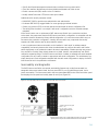
Figure 5. BL20p G2 Fibre Channel signal routing with the GbE2 Interconnect Switch
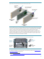
With the GbE2 Storage Connectivity Kit installed, both Fibre Channel SAN and Ethernet LAN signals
exit the rear of the server blade enclosure, each type of signal on its dedicated interconnect module
(Figure 6). Just like the LAN QuadT2 and QuadSX interconnect modules, the SAN OctalFC
interconnect module has a robust connector assembly and includes a guide pin to ensure that the
module is properly aligned as it is inserted. This unique modular design allows the switch to be hot-
swapped in seconds without re-cabling. The GbE2 Interconnect Switch front panel includes a SAN
LED indicating if a SAN interconnect module is installed.
Figure 6. Rear of server blade enclosure with both SAN and LAN interconnect modules installed
For additional information on the p-Class Fibre Channel offerings, please see the ProLiant BL p-Class
SAN storage connectivity technology brief
2
.
2
Available at http://h71025.www7.hp.com/support/reference_library/viewdocument.asp?countrycode=1000&prodid=5726|ProLiant+BL+p-
Class+System&source=TC030803TB.xml&dt=21&docid=20366.

11
Switch management
The GbE2 Interconnect Switch is an industry-standard managed Ethernet switch, which means that
users configure and manage the switch like other industry-standard Ethernet switches. To aid users
during initial deployment, the GbE2 Interconnect Switch includes a default configuration that is fully
operational at initial boot and a step-by-step set-up utility for custom configurations.
A web browser-based interface (BBI) and a command line interface (CLI) with scripting capability are
pre-installed in the switch firmware to configure, manage, and monitor the interconnect switch. The
interconnect switch also supports Telnet access and simple network management protocol (SNMP).
Any combination of the downlinks, crosslinks, and external ports can be disabled, enabled,
configured, and monitored on a per port basis. Out-of-band and in-band access to the switch
management interfaces are supported locally and remotely from anywhere on the network.
Administration of both GbE2 Interconnect Switches is possible through any uplink port, the serial port,
or the two 10/100/1000T ports conveniently located on the front panel of each switch (Figure 7).
Figure 7. ProLiant BL p-Class GbE2 Interconnect Switch front panel
Rapid deployment, back-up, and restore
HP Rapid Deployment Pack (RDP) for Windows version 1.40 or greater (RDP for Windows) introduces
a new feature called server-side scripting. With server-side scripting, interconnect switch scripts can
be integrated in an RDP for Windows job for deployment of both blade servers and switches. This is
ideal for using RDP for Windows to deploy a blade server and then configure associated switch
VLANs; however, any scriptable interconnect switch parameter can be integrated.
3
The GbE2 Interconnect Switch supports both trivial file transfer protocol (TFTP) and secure copy
protocol (SCP), which allows a copy of the interconnect switch configuration file to be saved and
downloaded either to the original switch or to a different interconnect switch. This provides a method
to rapidly deploy multiple systems with similar configurations and to provide backup and restore
capabilities. Configuration settings can be modified through the user interfaces or directly within the
3
For more information, see the white paper Using ProLiant Essentials Rapid Deployment Pack for scripted blade-based switch configuration at
http://h18004.www1.hp.com/products/servers/proliant-bl/p-class/bl-p-interconnect-switch2.html
.

12
configuration file. The configuration file has a text-based format, which allows it to be directly viewed,
printed, and edited. Each GbE2 Interconnect Switch has three configuration settings in memory
(active, back-up, and factory); any one of these settings can be selected as the current runtime
version.
Users can perform firmware operating system upgrades by using TFTP through any external Ethernet
port after boot-up, and by using XModem through the serial interface during boot-up. Redundant
firmware operating system images can be contained in memory; any system image may be selected
as the current runtime version. The interconnect switch simplifies system upgrades by retaining its
configuration after a firmware upgrade and by supporting the HP Support Paq automated firmware
upgrade process for Windows deployment stations.
IP addressing
Users can configure the GbE2 Interconnect Switch to automatically obtain an IP address from a
bootstrap protocol (BOOTP) server or they can manually assign an IP address through the command
line console interface. Users can also assign an IP address from the BBI; however, they would have to
reconnect with the newly assigned IP address. For increased security, an administrator can specify the
IP-based management network that is allowed to access the interconnect switch.
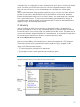
Web browser-based interface
Users can access the BBI by using Internet Explorer or Netscape Navigator over a TCP/IP network.
Thus, access is possible via any external Ethernet switch port. When log-in is complete, the BBI
Dashboard page opens by default in the web browser viewing window (Figure 8). The three main
regions of the Dashboard area as follows:
• The Toolbar displays the menu options for all windows.
• The Navigation Window contains particular items or features to select.
• The Forms Window contains options for viewing or altering GbE2 Interconnect Switch information.
Figure 8. Browser-based interface for ProLiant BL p-Class GbE2 Interconnect Switch

13
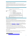
Scriptable command line interface
The CLI provides the added benefits of scripting, a set-up utility and other enhanced switch
management tasks, an out-of-band connection, and more. The main menu opens after a successful log-
in (Figure 9). This interface may be accessed locally via the front panel RS-232 console port on each
interconnect switch or remotely using a console Telnet session via any interconnect switch external
Ethernet port.
Figure 9. Command line interface for ProLiant BL p-Class GbE2 Interconnect Switch
Simple network management protocol
The GbE2 interconnect switch supports industry-standard SNMP management information bases
(MIBs), HP enterprise switch MIBs, and environmental traps. The SNMP agents are pre-installed in the
interconnect switch firmware. Redundant community strings and SNMP trap manager hosts can be
configured per switch
This capability allows the interconnect switch to be monitored remotely from an SNMP network
management station such as Insight Manager 7
4
or HP OpenView.
5
The interconnect switch may also
be configured through the HP OpenView Network Node Manager. The unique interconnect switch
integration with Insight Manager 7 provides the following additional features:
• A script utility to simplify registering (compiling) the GbE2 Interconnect Switch MIBs.
• Automatic discovery and identification of the interconnect switches upon registration of MIBs.
• Automatic receiving of traps and events from the interconnect switches upon registration of MIBs.
• Graphical representation of the p-Class server blades and interconnect switches (support for GbE2
Interconnect Switches is planned for 4Q2003).
Switch security
Several features are provided on the GbE Interconnect switch to allow the switch administrator to
secure the management interfaces. These features include the ability to:
• Configure multiple password protected accounts with various levels of access.
4
Available at http://www.compaq.com/products/servers/management/cim7-description.html.
5
Available at http://www.hp.com/products1/softwareproducts/software/openview/index.html.

14
• Specify the IP-based management networks that are allowed to access each switch.
• Set a user interface idle time-out period and disable web-based and Telnet access.
• Enable a secure shell (SSH) session to the CLI interface.
• Modify default Telnet and HTTP server socket port numbers.
Additional switch security measures include:
• RADIUS RFC 2865 to provide user authentication and authorization.
• Port-based IEEE 802.1Q tagged VLANs for server grouping and data isolation.
• Secure copy protocol (SCP) to securely upload and download the switch configuration file.
• The ability place the switch in an unique “safe mode” configuration with the included example
templates.
When users insert a new or replacement GbE2 Interconnect Switch into a production/real-time
environment, they must ensure that the GbE2 Interconnect Switch configuration is compatible with the
production network. Because the factory default configuration of a new interconnect switch may not
be same as the production configuration, inserting the new switch may compromise the security
aspects and VLAN isolation used by the production network.
A new or replacement interconnect switch can be installed in "safe mode" to address network
compatibility and security issues and to allow the administrator to configure the switch and finalize
switch deployment on the production network. Network compatibility includes spanning tree protocol
loop avoidance. Security issues include items such as VLAN isolation, user-passwords, and SNMP
read-write community strings. The GbE2 Interconnect Switch includes an example safe mode template
configuration file as a basis to create an appropriate safe mode configuration. The administrator can
simply download a final configuration template with the safe mode configuration to deploy the GbE2
Interconnect Switch in the production environment.
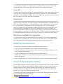
Serviceability and diagnostics
The GbE2 Interconnect Switch has several serviceability features such as the front-mounted, hot-
swappable interconnect switch blade, the front panel RS-232 port, Gigabit Ethernet ports, and a
power re-set switch. The interconnect switch also has system status LEDs and a LED annunciation panel
that displays the link speed and activity status for each port (Figure 10).
Figure 10. Front port LED panel for ProLiant BL p-Class GbE2 Interconnect Switch
*Uplink ports on the p-Class C-GbE2 Interconnect Kit are 10/100/1000T.
Uplink ports on the p-Class F-GbE2 Interconnect Kit are 1000SX.

15
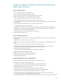
The optional HP Diagnostic Station (Figure 11) is available to configure and diagnose an interconnect
switch or a server blade that has been removed from the server blade enclosure. The Diagnostic
Station provides power to the interconnect switch and can be used to perform any of the following
tasks:
• Build the initial interconnect switch configuration.
• Download a switch configuration file.
• Test network adapter and interconnect switch port activity.
• Diagnose interconnect switch status.
• Test an interconnect switch after installing an option or upgrade.
Figure 11. Diagnostic Station
The GbE2 switch provides many additional serviceability and diagnostic features including:
• Port mirroring with the ability to mirror desired type of frames (egress, ingress, or both). A single-
source or multiple-source port may be mirrored to a destination port.
• Power on self test (POST) at boot for hardware verification.
• Monitoring screens via the user interfaces for port utilization, data packets received/transmitted,
error packets, packet size, trunk utilization, SNMP data, etc.
• Details of system information via the user interfaces such as port parameters and link status, switch
asset information, configuration values, log entries, etc.
• The ability to "ping" to identify connectivity and trace routes to determine station-to-station path
connectivity.
• Local system log (syslog) with ability to view and clear messages plus remote syslog with support for
a primary and secondary syslog servers.
• Settable non-volatile random access memory (NVRAM) diagnostic flags and display of management
processor trace buffer and snap or post-mortem trace buffer.
• State information ”dump” for tuning and debugging switch performance available in unencoded
format.
• Panic command for immediate state dump to flash memory and automatically switch reboot and a
watchdog timer for automatic switch reboot in case of switch software “freeze."
• MAC addresses view, clear, and delete from the forwarding database for identifying problems with
MAC address learning and packet forwarding.
• ARP table view, clear, entry, and delete for identifying problems with ARP entries.

16
• The ability to set the interconnect switch to a valid firmware image in case of firmware corruption.
For more detailed information on the administration capabilities of the ProLiant BL p-Class GbE2
Interconnect Switch, see the ProLiant BL p-Class GbE2 Interconnect Switch user guides.
6
Virtual LAN
The GbE2 Interconnect Switch supports 255 port-based IEEE 802.1Q virtual LANs (VLANs). Members
of a VLAN may be untagged and tagged ports according to IEEE 802.3ac VLAN Ethernet frame
extensions for 802.1Q tagging. Therefore, GbE2 switch VLANs may span other switches that support
802.1Q tagging located within the network infrastructure.
Spanning tree
The GbE2 Interconnect Switch meets the IEEE 802.1D spanning tree protocol (STP) and provides 16
spanning trees per VLAN basis. The spanning tree per VLAN implementation is compatible with Cisco
PVST+ (per VLAN spanning tree). The interconnect switch is also compatible with Cisco PVST when
the connecting switch is configured to use 802.1Q tagging or when it is running untagged.
Users can configure STP switch parameters, including priority and cost, on a per port basis. Each
interconnect switch can automatically find the STP root bridge on the network. Otherwise, the
interconnect switch will act as the root bridge for the STP domain. The spanning tree protocol may
also be disabled on a per switch or per port basis, which is ideal for networks designed without loops
or individual switch ports connected to server blades or other devices where a loop does not exist.
EtherChannel compatible link aggregation
The GbE2 Interconnect Switch complies with IEEE 802.3ad (802.3-2002) static link aggregation
(excluding LACP
7
) compatible with Cisco EtherChannel (Fast EtherChannel, Gigabit EtherChannel).
Each interconnect switch supports twelve multi-port trunks with up to six ports per trunk.
Enterprise-class performance
The GbE2 Interconnect Switch includes the following performance features:
• 24 Gb/s external port bandwidth per server blade enclosure (full duplex).
• 17.9 million packets per second maximum external port frame forwarding throughput per server
blade enclosure (64-byte packets).
• 2,048 MAC addresses per switch with automatic MAC address learning.
• 128-MB Main, 32-MB flash, and 2-MB packet buffer memory per switch (packet buffer memory
shared between ports).
• Internal 10 gigabit fabric for providing packet switching at 20 Gb/s data bandwidth full duplex
ProLiant Network Adapter Teaming
ProLiant Network Adapter Teaming is typically used to provide fault resiliency for the NICs within the
team. If one NIC should fail, the surviving NICs maintain network connectivity. However, network
adapter teaming may also be used to maintain network services if an Ethernet switch fails. The
architecture of the p-Class system allows for both network adapter and interconnect switch fault
tolerance when using ProLiant Network Adapter Teaming.
The ProLiant p-Class servers include standard HP NC series network adapters that support all three
types of ProLiant Network Adapter Teaming:
6
Available at http://h18004.www1.hp.com/products/servers/proliant-bl/p-class/bl-p-interconnect-switch2.html.
7
Link Aggregation Control Protocol.

17
• Network Fault Tolerance (NFT)
• Transmit Load Balancing (TLB)
• Switch-assisted Load Balancing (SLB)
When teaming HP NC series network adapters with the interconnect switch, NFT and TLB teaming are
the same as with any ProLiant system. However, for SLB teaming, the pre-defined switch-to-server
architecture across the server blade enclosure’s backplane must be considered. SLB requires that all
NICs in the team must be connected to the same switch.
The GbE2 Interconnect Switch’s redundant crosslinks add significant advantages when configuring
teaming for switch fault tolerance. For details, see the HP ProLiant network adapter teaming
white
paper
8
located on the ProLiant teaming home page.
Conclusion
The ProLiant BL p-Class system is a comprehensive solution for customers operating multi-tiered
environments that demand space and power efficiency, on-demand computing, end-to-end system
redundancy, rapid hardware and software deployment, and scalable management. The ProLiant
p-Class GbE2 Interconnect Kits are part of the family of interconnect options available for the ProLiant
BL p-Class system.
Meeting network requirements today and tomorrow, the extensive list of supported features, future
layer 7 switching, and 10 Gigabit Ethernet uplink capability built into every GbE2 Interconnect Kit
provide the most advanced Ethernet switching technology available in a blade format. Each GbE2
Interconnect Kit includes a pair of fully redundant, managed Ethernet switches that consolidate up to
thirty-two 10/100/1000 Mb/s gigabit network adapters to one to twelve external ports. These
options are ideal for reducing Ethernet network cabling and the time required to deploy, manage,
and service ProLiant BL p-Class systems.
8
Available at ftp://ftp.compaq.com/pub/products/servers/networking/TeamingWP.pdf.

18
Appendix: Summary of features of the ProLiant BL p-Class
GbE2 Interconnect Kit
Switch performance
• Store and forward mode layer 2 switching standard
• Layer 3 routing firmware future internal upgrade capability
• Layer 7 routing and content delivery switching future internal upgrade capability
• Support for 3rd party external layer 7 content delivery switch / appliance
• Support for F5 BIG-IP Blade Controller load balancer and traffic management
• Frame forwarding throughput of 1.488 million packets per second (per Gigabit port)
• 17.9 million packets per second maximum external port (uplink) frame forwarding throughput per server blade enclosure
(64-byte packets)
• 24.0 Gb/s External port (uplink) bandwidth per server blade enclosure (full duplex)
• 10 Gigabit Ethernet uplink future upgrade capability
• 128 MB Main, 32 MB flash, and 2 MB packet buffer memory per switch (packet buffer memory shared between ports)
• Auto-negotiation and auto-sensing with full-duplex support and ability to manually force port speed and duplex mode
• Auto-MDI/MDIX on all ports enabled with auto-negotiation
• 2,048 MAC addresses per switch with automatic MAC address learning
• ARP for IP to MAC address resolution
Switch network features
• IEEE 802.3 10Base-T Ethernet, IEEE 802.3u 100Base-TX Ethernet, IEEE 802.3ab 1000Base-T Ethernet, and IEEE 802.3z
1000Base-SX
• IEEE 802.1D spanning tree protocol (mono-spanning tree)
• PVST+ and PVST compatibility when VLANs are untagged or use 802.1Q tagging; up to 16 spanning tree domains per
switch
• Enable/disable and configure spanning tree port cost and priority on a per port basis
• IEEE 802.3ad link aggregation (excluding LACP) supporting up to 12 multilink trunk groups with 6 ports per group;
compatible with Cisco EtherChannel trunking (Fast EtherChannel, Gigabit EtherChannel)
• 255 IEEE 802.1Q port based VLANs per switch
• IEEE 802.3ac VLAN Ethernet frame extensions for 802.1Q tagging on a per port basis
• Tagged and untagged ports as members of a VLAN
• IEEE 802.3x flow control with manual configuration capability
• NTP (network time protocol) client with time zone support
• Real time clock (RTC) system time
Switch deployment and configuration
• Default pre-configuration for immediate plug-in operation in the server blade enclosure
• Set-up utility for a step-by-step customized configuration
• Communicate to any and all server blade network adapters from any Ethernet external port
• Manage both switches, access all iLO ports, and execute PXE from any external Ethernet port
• Web-based interface accessible from any switch port
• Command line interface (CLI) with scripting capability accessible from any switch port
• Telnet access to the CLI and menu-driven console interfaces accessible from any switch Ethernet port
• Integrated switch scripting within Rapid Deployment Pack for Windows v1.40 or greater
• One serial and two Ethernet ports conveniently located on the front of each switch for additional uplinks and local
management, port mirroring, and other administration and diagnostic tasks
• Configurable forwarding MAC address aging time settable to any value from 1 to 65,535 seconds (default is 300 seconds)

19
• MAC address user management sorting on a per port and per VLAN basis
• Manual, or automatic IP settings via a BOOTP server
• Three switch configuration settings in memory (active, back-up, and factory); any can be selected as the current version.
• Redundant firmware images in memory; either image can be selected as the current runtime version.
• Ability to restore switch to factory default settings
• TFTP and SCP to upload and download (save, restore, and update) the switch configuration file
• TFTP to upload and download (save, restore, and update) the switch firmware
• XModem to download the switch firmware (restore and update) via the serial interface
• Switch configuration retention after firmware upgrade
• HP Support Paq automated firmware upgrade process for Windows deployment stations
• Human read/write configuration file for viewing, printing, and editing
• DNS (Domain Name Service) client supporting primary and secondary DNS servers
• Pre-configured customized port naming with respect to server blade NIC connectivity
• ARP cache management table to display, add, and delete entries
• Ability to name ports on a per port basis
• Full ability to enable and disable any port (both internal and external ports) on both switches
• Two port disable levels: temporary (reverts to enable at switch boot) and permanent disable
Switch diagnostics and monitoring
• One serial port and two Ethernet ports conveniently located on the front of each switch for additional uplinks and local
management, port mirroring, and other administration and diagnostic tasks
• Front panel per port speed and per port link activity LED annunciation panel per switch
• System, management, and option compatibility status LEDs
• Per port speed and link activity LEDs adjacent to all external Ethernet ports
• Port mirroring with ability to mirror desired type of frames (egress, ingress, or both)
• Port mirroring single or multiple source ports to single destination port
• Switch statistic monitoring including port utilization, data packets received/transmitted, port error packets, packet size, trunk
utilization, SNMP data, etc
• System reporting such as port parameters and link status, switch asset information, configuration values, log entries, etc.
• SNMP v1 with two configurable community strings and SNMP trap manager hosts
• MIB-II, Bridge MIB, Interface MIB, Extended Bridge MIB, Ethernet-like MIB, Entity MIB, RADIUS Authentication Client MIB,
802.3-2002 Link Aggregation MIB, and HP enterprise switch MIBs
• Bridge, remote monitoring, and switch environmental traps
• Script utility to simplify registering (compiling) switch MIBs with Insight Manager 7
• Insight Manager 7 automatic discovery, identification, and receiving of traps and events, upon registration of MIBs
• Insight Manager 7 graphical representations of switches (planned for 4Q2003)
• Insight Manager 7 standard database activities (queries, tasks, reporting, etc)
• Power on self test (POST) at boot for hardware verification
• Portable Diagnostic Station to configure, upgrade, and diagnose an interconnect switch and server blade removed from the
rack environment
• Ability to return switch to a valid firmware image in case of firmware corruption
• Local system log (syslog) with ability to view and clear messages
• Remote syslog with support for a primary and secondary syslog server
• Ping capability to test the connectivity on the Ethernet network
• Trace route to identify the path used for station-to-station connectivity across the network
• Settable NVRAM diagnostic flags
• View information, clear, and delete specific MAC addresses from the forwarding database for identifying problems with
MAC address learning and packet forwarding
• ARP table view, clear, entry, and delete for identifying problems with ARP entries
• Display management processor trace buffer and snap or post-mortem trace buffer

20
• State information ”dump” for tuning and debugging switch performance available in uuencoded format
• Panic command for immediate state dump to flash memory and automatically switch reboot
Switch security
• Password protected multi-level user accounts supported on all management interfaces
• Configurable user interface idle time-out period
• Ability to disable web-based and Telnet access to the switch user interfaces
• 255 Port-based IEEE 802.1Q tagged VLANs per switch (510 per server blade enclosure)
• Ability to specify the IP-based management network that is allowed to access the switch
• RADIUS RFC 2865 user authentication and authorization
• Unique “safe mode” option to maintain production environment VLAN isolation and security aspects
• Configurable Telnet and HTTP server socket port numbers
• Secure shell (SSH) access to the command line interface
• Secure copy protocol (SCP) to securely upload and download the switch configuration file
Switch availability
• Front-mounted, hot-swappable switch with configuration retention and no need to cable/recable when removing
• Redundant switches per server blade enclosure
• Redundant uplink ports per switch
• Redundant front panel management/diagnostic ports per switch
• Redundant crosslinks for switch to switch communication and failover scenarios within the server blade enclosure
• Redundant pairs of network adapters per server routed to different switches
• Redundant Fibre Channel signals per each server passed through different switch chassis
• Redundant N+N hot-plug redundant power to each switch
• Redundant N+1 on-board cooling per switch
• IEEE 802.3ad automatic multi-link load balancing and link failover (excluding LACP)
• Load balancing of unicast traffic
• ProLiant network adapter teaming
• Redundant configurable community strings and SNMP trap manager hosts
• Redundant default gateways with automatic failover
• Redundant configurable Domain Name Service (DNS) client
• Redundant configurable syslog servers
• Redundant firmware images in memory; either image can be selected as the current runtime version.
• Redundant configuration settings in memory plus a third factory default file; any setting can be selected as the current runtime
version.
Switch investment protection
• Layer 3 routing firmware future internal upgrade capability
• Layer 7 routing and content delivery switching future internal upgrade capability
• 10 Gigabit Ethernet uplink future upgrade capability
• Supports any combination of ProLiant BL p-Class server blades
• Optional pass-through of ProLiant BL20p G2 Fibre Channel signals
Page is loading ...
Page is loading ...
-
 1
1
-
 2
2
-
 3
3
-
 4
4
-
 5
5
-
 6
6
-
 7
7
-
 8
8
-
 9
9
-
 10
10
-
 11
11
-
 12
12
-
 13
13
-
 14
14
-
 15
15
-
 16
16
-
 17
17
-
 18
18
-
 19
19
-
 20
20
-
 21
21
-
 22
22


HP ProLiant GbE2 User manual
- Category
- Network switches
- Type
- User manual
- This manual is also suitable for
Ask a question and I''ll find the answer in the document
Finding information in a document is now easier with AI
Related papers
-
HP 275 User manual
-
-
-
HP GBE2 User manual
-
-
-
-
-
-
Hewlett Packard Enterprise Virtual Connect Flex-10 User manual
Other documents
-
Compaq ProLiant BL strategy for rapid deployment and reprovisioning of high-density servers User manual
-
HP (Hewlett-Packard) 230859-004 User manual
-
Compaq BL20p - ProLiant - G2 User manual
-
Gigabyte GA-EX38-DS4 User manual
-
Belkin F1DG001-RMT Datasheet
-
Lantronix Switch 900-510 User manual
-
Cisco Systems 4840G User manual
-
Intel 1000SX User manual
-
-
 Blade ICE G8000 User manual
