Gigabyte GA-EX38-DS4 User manual
- Category
- Motherboards
- Type
- User manual
This manual is also suitable for

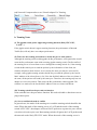
A. Teaming Part
a. Create Teaming Flow
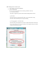
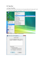
(i) From the start up menu, left click the icon in ProgramsÆRealtek Teaming and VLAN
Æ Realtek Teaming and VLAN Utility, as shown in the figure below:
(ii) The initialize user interface is showed below:

(iii) Teaming needs to set three parts
1. select adapters (at least two adpaters)
2. select teaming mode
There are three teaming modes for user choosing. (Default = 802.3ad)
(1) General Switch Mode
This mode is supported to general switch (without teaming function swtich).
(2) FEC/GEC
The mode needs the switch supports FEC/GEC. So, the switch has to setup
FEC/GEC mode and which ports are using for teaming.
(3) Link Aggregation \ LACP (802.3ad)
The mode needs switch support LACP. LACP is similar with FEC/GEC. But LACP
doesn’t setup which ports are using for teaming. LACP negotiates the ports with the
switch that will make up the team.

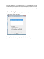
3. after selecting teaming adapter and teaming mode, click teaming button
(iv) If the Teaming created completely, the Dialog will show “Create Virtual Adapter For
Teaming Complete” and click OK.
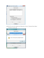
(There are two message boxes which are “Start
Disable Adapters” and “Start unbinding” show during creating teaming process)
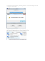
The step will cost one or two minutes.

(vi) Network Component has a new Virtual Adapter For Teaming
b. Teaming Notes
(i) The gigabit switch prefer supporting teaming function (likely FEC/GEC,
LACP…)
If the gigabit switch doesn’t support teaming function, the performance of Inbound
Traffic (Rx) will only have one adapter performance.
(ii) Take care the teaming switch how to decide the port to send packets
Although the teaming switch could upgrade the Rx performance, some particulars would
cause the Rx performance same with not using gigabit teaming switch. The Rx traffic of
the teaming server is from client to server through the teaming switch. So, if the teaming
switch decides which port to send the packets by the information of the client, the
situation all packets form client to server send by the same port may be occurred. For
example, some gigabit teaming switches decide the port send the packets by the last-bit
MAC address of the client (Source). So, if the last-bit MAC address of the two clients is
the same, all the packets will send by the same port. Therefore, the teaming only has one
adapter to receive the packets. That causes the Rx performance cannot upgrade. The
solution is to make sure the last-bit MAC address of the two clients is different.
(iii) Teaming switch has the port mirror function
Some switches have the port mirror function. We need to disable to function or not to
plug in these ports.
(iv) Server and Switch mode is conflict
In general case, the mode of the teaming server and the teaming switch should be the
same. When the mode of the teaming server is LACP and the mode of the teaming
switch is FEC/GEC, the adapters will send LACP packets to negotiate the ports with the
switch that will make up the team.
But teaming switch will ignore the LACP packets and
the network works likely FEC/GEC mode. When the mode of the teaming server is

FEC/GEC and the mode of the teaming switch is LACP, the teaming switch will send
LACP packets to the teaming server and wait the response form the teaming server. But the
teaming server will not reply the teaming switch due to set FEC/GEC mode. So, the teaming
is failed.
c. Remove Teaming Flow
(i) If without closing the user interface, directly click remove button.
(The selected adapters don’t care)
If closing the user interface and reopen it, directly click remove button
(Doesn’t need to select the adapter, it will remove all the virtual adapter)

(ii) If the Vlan removed completely, the Dialog shows “Remove Teaming Virtual Adapter
Finnished” and click OK.

B. Vlan Part
a. Create Vlan Flow
(i) From the start up menu, left click the icon in ProgramsÆRealtek Teaming and VLAN
Æ Realtek Teaming and VLAN Utility, as shown in the figure below:
(ii) The initialize user interface is showed below:

(iii) Click to select one adapter for Vlan (one adapter selected)
(iv) Click the Vlan button and start to create Vlan

(v) If the Vlan created completely, the Dialog will show “Create Virtual Adapter For Vlan
Complete” and click OK.
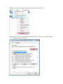
(vi) Network Component has a new Virtual Adapter For Vlan

(vii)Select the virtual Adapter and right-click to select “Properties”
(viii) The below figure is showed the properties. There, click the “Configure “Button
to setup the value of Vlan ID.

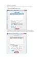
(ix) Select Advanced Page and Click Vlan ID properties to setup the value.

b. Remove Vlan Flow
(i) If without closing the user interface, directly click remove button.
(The selected adapters don’t care)
If closing the user interface and reopen it, directly click remove button
(Doesn’t need to select the adapter, it will remove all the virtual adapter)

(ii) If the Vlan removed completely, the Dialog shows “Remove VLAN Virtual Adapter
Finnished” and click OK.
-
 1
1
-
 2
2
-
 3
3
-
 4
4
-
 5
5
-
 6
6
-
 7
7
-
 8
8
-
 9
9
-
 10
10
-
 11
11
-
 12
12
-
 13
13


Gigabyte GA-EX38-DS4 User manual
- Category
- Motherboards
- Type
- User manual
- This manual is also suitable for
Ask a question and I''ll find the answer in the document
Finding information in a document is now easier with AI
Other documents
-
Fujitsu BX620 User manual
-
Dell Broadcom NetXtreme Family of Adapters User guide
-
Allied Telesis Network Card AT-2916SX User manual
-
Broadcom NetXtreme BCM57 Series User manual
-
Qlogic FastLinQ 3400 Series User manual
-
Cisco Systems 5709 User manual
-
Allied Telesis AT-2931SX User manual
-
Dell QLogic Family of Adapters User guide
-
Qlogic 3400 Series User manual
-