
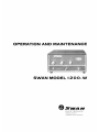
OPERATION
AND
MAINTENANCE
SWAN
MODEL
1200-W
EL
E C
TRONICS
O
ceanside,
California
A
Subsid
i
ary
of
Cubic
Corporation

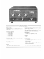
-----------SPECIFICATIONS-----------
POWER RATING
1200 Watts
PEP
Input in SSB Mode. 800 Watts DC
Input on
CW
.
5 FREQUENCY RANGES
I)
3,000- 4,500 kc
2)
6,000- 9,000 kc
3)
ll,000-16,000kc
4) 16,000-23,000 kc
5)
23,000-35,000 kc
USES
FOUR
6LQ6
TUBES,
Grounded Grid, Super-
Cathode-Drive Circuit.
DRIVE
REQUIREMENT
100-125 Watts
METER
Reads Relative
Output
and
Cathode
Current
Includes Transmit-Receive Relay Control for simple
operation with a Transceiver.
Wide range
Pi
Output
Circuit matches
52
or
75
ohm
coax cable or variety
of
other load impedances.
DIMENSIONS
13"
wide X 5-3/4" high X 10-3/4" deep.
WEIGHT
23lbs.
POWER
SUPPLY
Computer
grade electrolytic capacitors,
55
mfd. filter-
ing
at
1200
VDC
rating.
Silicon Rectifiers.
AC Input:
117
volts, 50-60 cycles, 400 watts average
input with voice modulation.
230 volt, 50-60 cycle model available on special order.

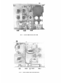
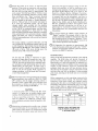
FIG
. 1 - 1
200-W
AMPLIFIER,
TOP
VIEW
FIG
. 2 -
1200-W
AMPLIFIER,
BOTTOM
VIEW

INSTALLATION
.
CAUT
.
ION
Never remoye the cabinet or bottom plate when
power line voltage
is
connected. Highly lethal volt-
age
is
used
in
this amplifier.
Allow
at least one
minute
for
capacitors to discharge after turning the
amplifier
off
and pulling the plug.
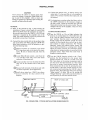
GENERAL
(a) Refer to the pictorial
in
Fig. 3 when making the
installation. Connect a short length
of
coaxial cable
(RG-58 or RG-8) from the transceiver or exciter to
the coaxial input
jack
on the 1200-W. A PL-259 type
connector is required
at
the amplifier end
of
the
cable. This cable should be as sh0rt as practical and
preferably not more than 5 feet long.
(b) Connect the relay control cable to the auxiliary relay
jack
on the Swan 270. When using the 1200-W with
other Swan transceivers it will be necessary to per-
form the following steps:
Q)
Remove
bottom
of
transceiver
and
install
RCA
type phono
jack
on the back
of
the trans-
ceiver.
Be
sure to insulate the jack from the
chassis.
@Locate
Relay
Kl
and connect a wire from the
+
12
volt side
of
the relay coil to the center
conductor
of
the phono
jack.
G)
Connect another wire from the other side
of
the
relay coil to the common side
of
the phono
jack
.
@By-pass
both terminals
of
the phono
jack
with
.0 I
mf
disc capacitors. (TVI suppression)
@Install
phono plug from 1200-W into phono
jack
on transceiver for relay control
of
the
amplifier.
MCK
Of
1200-W
IN
OUT
(c)
Connect the antenna coax, or dummy load to the
output
jack
.
If
a low pass filter
is
to be installed to
reduce TV I, connect it between the output
jack
and
the antenna.
(d) For transceivers
or
exciters other than Swan, refer to
the 1200-W schematic for the necessary changes
in
the relay circuit. Locate the terminal strip with the
black and red wires from the control cable. They are
located
at
the rear
of
the amplifier. These two wires
must be reversed.
TUNING
INSTRUCTIONS
(I)
Turn the 1200-W on. The red light indicates
that
power
is
on and the filaments
of
the 6LQ6 tubes will
be
lit. Turn the 1200-W function switch to the "By-
pass" position. Tune the exciter
or
transceiver first.
Exciter
output
will be
shunted
around
the
linear
amplifier by the internal relay, and will go to what-
ever
antenna
or
load
is
connected
. The
"Output
Metering" control will indicate exciter output, and
may be used conveniently as a tuning meter. Simply
adjust
the
exciter
control
s for
maximum
output,
using whatever tuning procedure is prescribed for the
particular exciter. Then switch the exciter back to
standby or receive position.
0
Turn
the 1200-W function switch to the
"Tune"
position.
Set
the
bandswitch
to
the
proper
band
position and the P.A. Load to 9 o'clock. Turn the
Mic. Gain down on the exciter (transceiver) and
be
sure the carrier has been balanced out. Then switch
the exciter to normal voice-transmit position. With
Swan transceivers this
is
done by pressing the push-
to-talk button.
If
the relay control circuitry
is
prop-
erly connected and functioning, the 1200-W
is
now
in
transmit mode. The 6LQ6 tubes will now
be
drawing
"idling current"
of
about
100
rna.
By
turning the
"Output
Metering" control fully counterclockwise to
the off position you will read cathode current. ·
BACk
Of
SWAN
270
ANT.
RG-58
CONTROL
CABLE
LO
-
PASS
TV
FILTER
COAX
TO
ANTENNA
FIG.
3
REAR
VIEW-
TYPICAL
INSTALLATION
USING
SWAN
270
3

@Switch
the exciter to its
"Tune
"
or
full
CW
power
position.
(If
an
exciter
or
transceiver with
more
drive
than
the
Swan
270
or
260 is used, it is
recommended
that
the
drive be
kept
down
to
approximately
100
watts
output.
With
the
Swan
500
or
350 this is
done
by inserting
approximately
250
MA
of
carrier
rather
than
switching
to
the
"Tune"
position).
Quickly
adjust
P.A.
Tune
on the 1200-W for
maximum
out-
put
, as indicated by the
meter
in
"Output
Metering"
position.
Then
go
back
to
the exciter
and
adjust
its
P .
A.
Tune
for
maximum
output.
(It
may
have
changed
slightly when switched
into
the amplifier
cathode
circuit.)
Next
advance
the P.A.
Load
control
on
the 1200-W for increased
output,
and
then alter-
nate
between adjusting
P.A.
Tune
and
P.A.
Load
until
the
highest possible
output
indication
is
reached.
Then,
advance
the P.A.
Load
control
about
I
number
higher
and
adjust
P.A.
Tune
for
maximum
output.
This
last
tuning
adjustment
will provide best linearity
and
efficiency.
The
output
reading
is a relative indication,
and
will
vary co,nsiderably with different
antenna
loads as well
as with frequency.
The
Cathode
Current
should
read
approximately
500-600
MA.
This
reading
is
based on
100
watts
of
drive.
With
more
driving power the
cathode
current
will
of
course
read
higher.
CAUTION
Do
not
keep the exciter
or
transceiver
in
tune
position
for
longer than 30 seconds at a time. This
caution note concerns the exciter more than the
I200-
W,
but since the 6LQ6 power amplifier tubes
are operating at
full
input during tune, the time
should
always be
kept
short.
If
longer
time
is
required, switch to standby
for
a minute, and then
back to tune
for
30 seconds. With experience
in
tuning procedures, it will be
found
that 30 seconds
is
more
than enough time.
@
SSB
Voice
Operation.
Having
followed the preceding
tuning
procedures, now switch the 1200-W
to
"SSB-
CW"
position,
and
the
output
metering
control
to
Cathode
Current.
Apply
SSB
voice
excitation
from
the transceiver
or
driver,
and
advance
its Mic.
Gain
control
for a
peak
reading
of
300-400 rna.
CAUTION:
I) Exercise great care
in
setting
the
Mic
Gain
control. It
is
quite easy to produce higher meJer
readings, butflattopping and distortion will result.
2) Do not switch the exciter into
"Tune"
position
when the 1200- W
is
in
"SSB-CW"
position. Only
voice modulated excitation should be applied
in
this
position.
Q)
Monitoring
and
tuning with
an
oscillo~
~c
ope.
A highly
recommended
piece
of
test
equipment
for the
com-
plete
amateur
radio
station
is
an
oscilloscope suitable
for
monitoring
.
transmitter
output
and linearity. This
4
----
------
----------
-
-----
--
--------
----
--
----
- -
--
instrument
will
permit
optimum
tuning
of
both
th
e
driver
and
amplifier
, as well
as
continuous
mon-
itoring
during
operation
.
An
excellent oscilloscope
is
the
Heath
model
SB-6\0
sold in kit form by the
Heath
Co.
of
Benton
Harbor,
Michigan.
The
instruc-
tion
book
supplied with this
kit
explains in detail
how
to
connect
and
use
the
instrument
,
and
how
to
interpret
the screen
patterns.
Other
oscilloscopes
may
also be used.
The
Radio
Amateur
's
Handbook,
pub-
lished by the
ARRL,
and
the
Radio
Handbook
by
Bill
Orr,
published by
Editors
and
Engineers
both
contain
detailed
information
on
the
use
of
os-
cilloscopes
for
transmitter
tuning
and
operation.
These publications
are
recommended
references for
this
purpose
.
@To
operate
without
the 1200-W, simply switch
it
to
"Bypass"
position.
The
antenna
circuit is
then
by-
passed
around
the amplifier by the
internal
relay
and
the transceiver-driver will
operate
"Barefoot."
How-
ever, the
6LQ6
filaments in the 1200-W
remain
lit
to
allow
instant
operation
of
the amplifier.
G)
CW
Operation:
for
operation
at
approximately
500
watts, the function switch
may
be left in
the
"TUNE"
position.
For
full power
operation,
place the function
switch in the
SSBjCW
position.
MAINTENANCE
There
will be little
maintenance
required in the 1200-W
amplifier.
The
6LQ6
tubes will provide
thousands
of
service
hours
when
operated
according to instructions.
Deterioration
of
a
tube
will generally be indicated by a
change in idling
current
or
inability to
draw
normal
plate
current,
or both. However, except for occasional field
problems which
may
occur with
any
electronic device,
the tubes
may
be expected to
operate
month
after
month
and
year
after
year
with no problems. In the
grounded
grid circuit,
matching
of
the
6LQ6
tubes is
not
normally
required.
Other
components
are
also
operating
conservatively,
and well within
nominal
ratings.
The
electrolytic filter
capacitors
in
the
power
supply
are
computer
grade,
meaning
that
they have a
much
higher degree
of
purity
and
quality
control
than
conventional types. Life expec-
tancy
of
these filters
is
approximately
\0
years.
The
silicon diodes used in the supply
are
hermetically sealed
and
are
not
likely
to
ever fail or
wear
out.
DIAL SETTING
BAND
PLATE
LOAD
80
40
20
15
10
5
4.5
7.5
6
7
TYPICAL
DIAL
SETTINGS
ON
1200-W
WHEN
COUPLED
TO
A
50
OHM
LOAD
3
2.5
4
3
4

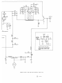
INPUT
0
0
~----~l~------~-----------+----------~~~---1
I
.OOZ
I
I
I
I
I
I
I
I
I
Kit
I
117
VAC
I
1
Kl
I
I
>
8
"'
I
<
aYPASS-
T
1
SSil
t- 750 UNDER LOAD)

10
~IZVAC
JN
EI
CW-
"-
:E:
>
0 0
~r~
..r::
)
0
..r::
)
.....
SELECTED
Z70
CATHODE
OUTPUT
OUTPUT
IZVAC
Kl
MODIFICATION
FOR
USING
IZOO-W WITH TRANSCEIVERS
ElR
EXC I
TEBS
OTHER
THAN
SWAN
-----
-------'
SCHEMA
TIC
DI
AG
RA
M - S
WAN
CY
G
NET
LI
NE
AR
AMP
LIFIER - M
ODEL
1200- H
® 5- 12-
70

WARRANTY POLICY
Swan Electronics Corporation warrants this equipment
again
st
defects in material or workmanship, except
for
tubes, transistors.
and
diodes. under normal service
for
a
period
of
one
year
from
date
of
original
purchase.
Tubes. transistors. and diodes are covered under the
warranty policy
for
a period
of90
days. This warranty
is
valid
only
if
the enclosed
ca
rd
is
properly fiJled
in
and
mailed to the
factory
within ten days
of
date
of
purchase.
Do
not
ship to the
factory
without prior authorization.
This warranty
is
limited
to
repairing or replacing
only
the defective parts. and
is
not valid
if
the equipment has
been tampered
with, misused or damaged.
-
 1
1
-
 2
2
-
 3
3
-
 4
4
-
 5
5
-
 6
6
-
 7
7
-
 8
8


Ask a question and I''ll find the answer in the document
Finding information in a document is now easier with AI
Related papers
-
Swann 1200W User manual
-
-
-
-
Swann 400 Operation And Maintenance
-
-
-
Other documents
-
AMERITRON AL-800XCE User manual
-
 AMERITRON Al-800H User manual
-
 AMERITRON AL-572 User manual
-
 Ehrhorn Technological Operations ALPHA 76PA Operating And Technical Manual
-
 AMERITRON AL-80BX User manual
-
-
 AMERITRON AL-1200X User manual
-
DRAKE L7 User manual
-
 Alpha Power ALPHA 89 Specification
-
 AMERITRON ALS-1306A User manual


