Page is loading ...

AMERITRON ALS-1306
1200 WATT 160-6 Meter NO TUNE
TMOS-FET AMPLIFIER
INSTRUCTION MANUAL
116 Willow Road
Starkville, MS 39759 USA
662-323-8211

Version 2
2
Amplifier Features
This amplifier provides the following standard features:
• 160- through 6-meter operation, full-power on six meters
• Eight conservative linear-service rated, 50-volt MOSFET transistors
• New push-pull stripline PA layout with exceptional VHF performance
• Energy-efficient solid-state design greatly reduces heat, <100-watts power line draw on
receive
• Exceptional harmonic suppression
• Operational in a few seconds, no long filament warm-up time
• Clean layout with easy-to-service modular construction
• Quiet variable-speed forced-air cooling system
• Power module current and voltage meters with LED illumination
• Accurate PEP Forward and PEP Reflected output power metering
• Power module balance metering with PA unbalance protection
• Reflected power protection
• Thermal overload protection
• Bandswitch error protection
• Easy to understand front panel LED indicators for rapid fault-error diagnosis
• Standard negative-going ALC output with front panel adjustment
• ALC metering and ALC LED indicator
• Fully-regulated external power supply
• Compact size 17.5” deep x 7” high x 10.5” wide
• Weight amplifier section 23 pounds

Version 2
3
Quick Start
Thank you for purchasing this amplifier system. The ALS1306 is a 1200-watt nominal PEP
output amplifier and power supply system. This amplifier covers 160-6 meters. Nominal drive
power is 100 watts or less. This system will not and does not operate on the CB band.
The ALS1306 interfaces with most modern amateur radio transceivers, including band data
information. Band data connection will require purchasing an Ameritron interface cable for your
radio.
Carefully unpack this amplifier and power supply. Cabinets and controls can be broken, bent, or
dented with rough handling. Please inspect everything for physical shipping damage; this
includes cabinets and chassis. Ameritron does not package dented or damaged units. If your unit
is damaged or dented, including broken knobs or switches, it is always from handling somewhere
between Ameritron and the end user. In the event of cabinet damage or broken controls, please
retain all packing materials and containers so damage claims can be resolved.
Installation and Operation
Placement
WARNING: Do not block ventilation holes. Do not expose to water or external heat.
This unit is two units, a power supply and an amplifier section. The power supply, within limits
of cable length, can be placed out of the way. The amplifier section should be in a convenient
location within arm’s reach of the operating position.
Wiring
Power Mains
1.) This amplifier requires a 200-260 Vac, 50-400 Hz, 15-ampere or larger mains supply. This
range includes all typical power lines worldwide, including USA 240-volt systems
(sometimes incorrectly referred to as “220 volt”).
2.) The plug is a NEMA 6-15P, 250 maximum Vac at 15 amperes. This is a standard USA
250V plug with a safety ground pin
3.) The amplifier’s power supply system contains two 30-ampere 50-volt supplies, one for
HV1 and the other for HV2. The supply can be damaged by operation with voltages below
200 volts or above 260 volts.
4.) Larger power wiring will not help performance or power unless amplifier high voltage is
unstable.
5.) While not recommended, the power supply can be rewired for 100-130 Vac operation.
The increase in power line current with reduced power line voltage will limit amplifier
power.
6.) The ALS-1306 power supply system is voltage regulated. You should see very little
change in HV1 and HV2 with amplifier power. Less than 3 volts change from the 50Vdc
nominal voltage is normal.

Version 2
4
7.) The ALS-1306 has two power supply boards in the power supply. Exceeding safe power
supply current on any supply line will force the overloaded supply into shutdown.
Shutdown is reset by turning the main power switch off for a brief time. If the power
supply has a permanent overload or the supply has failed, it will not reset.
Radio and Antenna Connections
WARNING: Forcing connector engagement can result in permanent connector damage.
Solder on the outside of center pins or bent pins are primary causes of female connector
damage. External solder or bent center pins will permanently damage the female.
Do not use Line Isolators on amplifier RF cables. The chassis of the amplifier should be at
the same RF potential as all other desk equipment. Shield isolators allow equipment to float
to different RF chassis potentials. Different chassis potentials are exactly what we do not
want, and isolators on desk coaxial cables encourage different potentials. It is better to cure
RF problems outside the operating position whenever possible.
1.) RF connections are through standard UHF female connectors. Use good cables with
quality UHF male (PL259) connectors. The output cable must safely handle at least 1200
watts.
2.) Look at the connectors. The amplifier‘s female connectors have notches on the outer
thread edge. The cable males should have protruding tabs on the inner shell beyond the
center pin insulator. These tabs and notches prevent unwanted connector rotation. The
male’s tab or tabs must be aligned with the female’s notches. This interlocking prevents
connector rotation.
3.) With a firm handgrip, gradually tighten RF connectors while making sure the male tab
interlocks with the amplifier’s female connector notch. Do not use excessive force on
connectors. Check for proper tightness and seating by wiggling and flexing the cables
near the connector and watching for any indications of abnormal male connector
movement, and by wiggling the cable while hand tightening the male shell. If done
properly, the connector will be solidly locked without need for pliers or other tools
4.) ALC and Relay (keying) connectors are phono females. The phono males from external
cables should push directly in with a snug fit.
5.) The Relay line has low-voltage (<12V) low current (<20 mA). Transmit is enabled by
pulling the Relay line to ground with a relay contact or transistor. Read your radio
manual. Unless you have a very unusual radio, your radio will directly key the amplifier.
6.) The remote and radio band data connectors are specialized connections. They are for use
with Ameritron supplied cables only.

Version 2
5
Operation
This amplifier has alert codes. SWR, PA, TX, and band switch lamps indicate operational faults.
Operational faults reset by placing the amplifier in standby momentarily. The following table
applies to faults:
Warning
light Steady
Warning
light Flash
Fault Cause or Cure
SWR TX
Antenna Reflected
Power
High antenna SWR or
intermittent antenna or feed line
connection
SWR, PA Band
Wrong filter Exciter or amplifier on
incompatible band, filter failure
PA TX
PA FET too hot Excessive power for duty cycle
or SWR, lack of proper airflow
PA Combiner unbalance
10M, PA,
TX
Illegal 11 meter Excessive 27 MHz signal level
REM, PA
No or wrong band when
on remote
Defective or improper remote
cable, or bad radio band data
information
Before attempting operation:
1.) This amplifier is optimized for a 50-ohm load. Be sure your antenna system 50-ohm
SWR is as low as possible. As SWR increases from 1:1, either heat or distortion
will increase.
2.) Be sure your antenna system, including any lighting protection devices, will safely
handle high power.
3.) Connectors, cables, and antennas must not have loose connections or insulation
issues.
4.) Your exciter must be less than 100 watts output.
5.) Power mains should capable of 15 amperes, reasonably stable, and 200-260 volts.
6.) The low pass filters cut off just above traditional primary bands. This means
primary filters are used on WARC bands. Some radios do not supply enough band
data to know the exact band, so with some radios the amplifier band data displays
the next higher primary band above a WARC band. Do not be alarmed if, for
example, 15 meters illuminates when 17 meters is selected on some radios.
7.) The amplifier will automatically attempt to reduce power if it appears thermal
limits will be reached.
8.) The amplifier will shut off if an incorrect band is selected, if antenna SWR is too
high (even for an instant), if thermal limits are reached, or if there is a catastrophic
failure.
9.) The alert codes are in a table above on page 10.
10.) The ALS-1306 metering reads peak envelope power on all RF power functions.

Version 2
6
With proper installation, basic operation is straightforward:
1.) Set the bandswitch to the desired band. This happens automatically in the REM position
with a suitable radio interface cable
2.) Set the exciter or transceiver to the desired power below 100-watts.
3.) Place the standby switch in the operate position
4.) Transmit, and watching Forward Power metering, be sure power does not exceed 1200-
watts on peaks.
5.) For high duty cycle modes and long transmissions, reduce power. The amplifier will
attempt to reduce power if the FETs approach safe limits.

Version 2
7
Table of Contents
QUICK START ........................................................................................................................................................... 3
INSTALLATION AND OPERATION...................................................................................................................... 3
PLACEMENT...............................................................................................................................................................3
WIRING......................................................................................................................................................................3
Power Mains ........................................................................................................................................................3
Radio and Antenna Connections..........................................................................................................................4
Operation .............................................................................................................................................................5
AMPLIFIER FEATURES .......................................................................................................................................... 2
AMPLIFIER FEATURES .......................................................................................................................................... 2
INTRODUCTION ....................................................................................................................................................... 9
POWER SUPPLY........................................................................................................................................................ 9
Power Line Requirements ....................................................................................................................................9
Power Supply Features ........................................................................................................................................9
Power Supply Location ......................................................................................................................................10
GENERAL INFORMATION................................................................................................................................... 10
Alert Codes.........................................................................................................................................................10
Amplifier Overview ............................................................................................................................................10
INSTALLATION....................................................................................................................................................... 11
Installation Clearances ......................................................................................................................................11
Installation Warnings.........................................................................................................................................12
Installation, Wiring, and Connections ...............................................................................................................12
Station Ground...................................................................................................................................................12
Safety and Lighting Grounding..........................................................................................................................13
INTERCONNECTION WIRING ............................................................................................................................ 14
AMPLIFIER REAR PANEL.................................................................................................................................... 16
Optional Radio Interface Cables........................................................................................................................17
FRONT PANEL......................................................................................................................................................... 18
OPERATION ............................................................................................................................................................. 19
MARS or CAP Operation...................................................................................................................................19
WARNING LIGHTS....................................................................................................................................................20
Initial Operation ................................................................................................................................................20
ALC ADJUSTMENT ..................................................................................................................................................21
ALS-1306 FUNCTIONAL OVERVIEW................................................................................................................. 22
General Operation .............................................................................................................................................22
Power Division...................................................................................................................................................22
PA Amplifiers .....................................................................................................................................................22
2KWF6 Lowpass Filter Assembly ......................................................................................................................23
Control and Protection Logic ............................................................................................................................23
SWR....................................................................................................................................................................23
CIRCUIT BOARDS .................................................................................................................................................. 24
2KWF6 ...............................................................................................................................................................24
BS2 .....................................................................................................................................................................24
CB2 ....................................................................................................................................................................24
MB1....................................................................................................................................................................24
PA Boards ..........................................................................................................................................................24
PD8 ....................................................................................................................................................................24
RJ45 ...................................................................................................................................................................24
RLY.....................................................................................................................................................................24

Version 2
8
SWR....................................................................................................................................................................25
SCHEMATICS .......................................................................................................................................................... 26
Filter 2KWF6 .....................................................................................................................................................26
Bandswitch BSW3 ..............................................................................................................................................27
Interface Connections RJ45 ...............................................................................................................................27
Control Board CB2 ............................................................................................................................................28
Power Divider PD8............................................................................................................................................29
SWR Sensor Board .............................................................................................................................................29
Metering Board MB2 .........................................................................................................................................30
PA Module .........................................................................................................................................................31
RLY Relay Board................................................................................................................................................31
ALS-1300SPS .....................................................................................................................................................32
AC Mains Selection............................................................................................................................................33
REFERENCE FIGURES AND DRAWINGS ......................................................................................................... 34
TABLES ..................................................................................................................................................................... 34
DISCLAIMER ........................................................................................................................................................... 35
LIMITED WARRANTY............................................................................................................................................. 36

Version 2
9
Introduction
The Ameritron ALS-1306 is 1200-watt nominal output, 160 through 6-meter amateur radio band,
solid-state amplifier. The ALS-1306 uses eight 50-volt, conservatively rated, linear RF
MOSFETs. These MOSFETs are specifically designed for linear power amplifier applications,
not class C or pulse service. They provide exceptionally low SSB distortion when compared to
other solid-state devices. Fan speed is regulated by temperature sensors; assuring conservative
cooling with minimal noise.
Nominal driving power is 100-watts for 1200-watts output (approximately 11 dB gain) on most
bands. The compact 10” wide by 6-1/2” high amplifier package (depth only 18”) fits nearly any
station configuration. The attractive desktop amplifier unit weighs only 24 pounds.
An external 50-volt 50-ampere regulated power supply powers the ALS-1306. The supply is
wired for 240 VAC (200-260 VAC, 50-60 Hz, 15 amperes), but can be rewired for 120 VAC
operation for lighter duty operation.
Power Supply
The external power supply for the ALS-1306 is a voltage-regulated current-limited switching
supply. It contains 14-volt positive and negative supplies, as well as dual 50-volt 25-ampere
continuous (30-ampere peak) fully current-limited supplies. Each PA (power amplifier) module
in the ALS-1306 operates from independent 50-volt modules, giving a total dc supply rating of
2500 watts average power and 3000 watts peak power to the power amplifier modules.
Power supply to amplifier interconnections are through a heavy-duty cable using a large Cinch
Jones connector.
Power Line Requirements
This amplifier ships wired for a nominal mains voltage of 230 Vac. Maximum average power-
line current at full power output is 12 amperes at 240 volts. Two 250-volt 15-ampere fuses fuse
the power line. The switching power supply automatically adapts to any mains voltage between
200 Vac and 260 Vac, and does not require adjustments or tap changes within that range.
Note: 120-volt power mains operation is possible with a reduction in CW or RTTY power.
Because average power is very low, SSB operation is unaffected by 120-volt operation. 120-V
fuse size is 25-amperes maximum.
Power Supply Features
• Efficient operation from 200-260 volts ac (12 amperes typical at full output power).
• Low standby and receive power drain, typically less than 100-watts.
• Generator and inverter friendly with acceptable power line frequency range 40 to 400 Hz.
• Fully regulated current-limited outputs.
• Step-start to limit stress on power supply components.
• Exceptional filtering and RFI suppression eliminates receiver birdies common to most
SMPS.
• Compact light weight design.

Version 2
10
Power Supply Location
Locate the power supply in a convenient ventilated area near the amplifier location. Avoid
placing the power supply next to sensitive equipment, such as audio processors, transceivers, or
microphones. For safety, ground the wing nut stud on the supply rear to the station ground buss.
The station ground buss should comply with National Electrical Codes. NEC and fire protection
codes mandate directly bonding of station grounds to the power-line entrance ground. If station
ground rods are not bonded to the utility entrance ground, likelihood of equipment or property
damage and personal risk increases.
General Information
Alert Codes
The SWR, PA, TX lamps, and band switch lamps indicate operational faults. Operational faults
reset by placing the amplifier in standby. The following table applies to faults:
Warning
light Steady
Warning
light Flash
Fault Cause or Cure
SWR TX
Antenna Reflected
Power
High antenna SWR or
intermittent antenna or feed line
connection
SWR, PA Band
Wrong filter Exciter or amplifier on
incompatible band, filter failure
PA TX
PA FET too hot Excessive power for duty cycle
or SWR, lack of proper airflow
PA Combiner unbalance
10M, PA,
TX
Illegal 11 meter Excessive 27 MHz signal level
REM, PA
No or wrong band when
on remote
Defective or improper remote
cable, or bad radio band data
information
Amplifier Overview
The Ameritron ALS-1306 is a solid-state, 1200-watt nominal RF output power, 1.8-54 MHz
amplifier. The ALS-1306 meets or exceeds all FCC requirements governing amateur radio
external power amplifiers.
The ALS-1306 uses four pairs of exceptionally low distortion, push-pull MRF-150 (or
equivalent) SSB RF power transistors. The characteristics of linear high-voltage FETs are very
much like those of triode vacuum tubes. While this amplifier will run more than 1200 watts PEP
output, linearity might suffer. Ameritron recommends running 1200 watts or less peak power for
maximum linearity. If these instructions are followed this amplifier will have comparable IM
performance to the best vacuum tube linear amplifiers.
Temperature sensors on each PA (power amplifier) module monitor heat. Bias and fan speed
track FET temperature. The ALS-1306 protection circuitry reduces power as transistors approach
conservative thermal limits, and disables the amplifier before transistor exceed safe operating
temperature limits.

Version 2
11
Harmonic suppression comes from push-pull operation of linear devices, followed by high-
quality 5-pole low-pass filters. Many amplifiers use inexpensive ceramic disc or mica capacitors.
Lead inductance of mica or disc capacitors reduces high-order harmonic suppression. This
amplifier uses quality multi-layer high voltage chip capacitors.
This amplifier greatly exceeds FCC harmonic requirements. HF harmonic suppression typically
10-15 times better than FCC mandated suppression levels. Harmonics are practically
immeasurable on all television channels. An external low-pass filter has minimal effect with this
amplifier.
Antenna switching is through a pair of sequenced miniature relays on a plug-in module. This
facilitates relay servicing or maintenance. Relay switching time is approximately five
milliseconds. The T/R “Relay” control jack is well within the range of almost any transceiver or
radio. The “Relay” jack has an open circuit voltage of 13-volts, and closed circuit current less
than 20 mA. Virtually any modern amateur radio will directly key this amplifier.
This amplifier includes full metering using large easy-to-read conventional panel meters. The
meters read all critical parameters including forward and reflected peak envelope RF power.
Installation
Please look your amplifier and power supply over carefully. Observe the air inlet and outlet
ventilation holes. Facing the amplifier front panel, the cooling air inlets are on the top left and
lower right side, including the right bottom. The warm air outlet is on the lower left side of the
cabinet as viewed from the normal operating position (front view). While outlet air will not be
particularly warm, it is never a good idea to have warm air blow into heat sensitive equipment,
such as transceivers or other power amplifiers. Have the same consideration for your new
amplifier and power supply. Be sure the air inlet temperature is not substantially above normal
room temperature. Ideally, the air inlet temperatures should be below 32° C or 90° F, although
temperatures up to 41° C or 106° F are permissible. If ambient temperatures exceed these limits
it might become necessary to reduce duty cycle or power.
Warning: Do not block cooling air inlets and outlets!
Never expose the amplifier to water or mist.
Installation Clearances
The amplifier must have a clear area to the bottom, both sides, and top for proper airflow, and to
the rear for interconnection wiring. It is especially important to avoid obstructions that block the
air inlet on the top left, as well as both lower sides. Two inches clearance is normally adequate
for full ventilation. Keep any papers or loose objects that might impede airflow away from the
air inlets and outlets.
Locate the amplifier and power supply away from sensitive equipment such as microphones,
audio processing equipment, or low level audio or radio frequency amplifiers. Generally, the best
location for the power supply is below the operating desk and away from antenna feed lines. This
will keep fan noise and any RF coupling to a minimum.

Version 2
12
The power supply has an air inlet at the rear, and air outlets on the top. The highly efficient
power supply produces very little heat, but the inlet and outlet must remain open to normal room
temperature air.
Installation Warnings
Accessory Equipment and Devices
One of the most common causes of amplifier failures or erratic fault protection alarms is
installation of antenna switches, lightning protection devices, or baluns with lightning spark gaps
in high SWR lines. If your antenna system has an SWR high enough to require an antenna tuner,
do not use 50-ohm lightning protection devices after the tuner.
Installation, Wiring, and Connections
The power supply is factory wired for 200-260 Vac. It uses a standard NEMA-6-15P 15-ampere
240-volt plug. The round center pin is the safety ground. Do not remove the safety ground.
CAUTION! Before connecting the power supply to an electrical outlet, always be sure you have
completed the following four steps:
1. Insert the 15-ampere 250V fuses into the two black fuse caps.
2. Insert the fuse and cap assemblies into the power supply’s fuse holders. The fuses lock in
place with a slight turn.
3. Connect the power supply to the amplifier.
4. Be sure the amplifier power switch is off.
Caution! Fuses have both voltage and current ratings. Use only
250V rated fuses in this device. The voltage rating is generally
marked on fuses. DO NOT use automotive-type low voltage fuses in
any power line application. For 240-volt operation, 15-ampere fast
blow fuses are required.
Warning: Never insert the power supply cord into the outlet until
you have completed the four steps above!
Position the amplifier at or near the desired location on your operating desk so you have access
to the rear panel, and connect the rear panel cables. Do not connect the power mains at this time!
Station Ground
Common rumor is that a station equipment ground reduces RFI (radio frequency interference),
reduces lightning damage, or improves signal levels. Generally, changes in RFI or signal quality,
with the addition or removal of a station ground, indicate an antenna or feed line installation
problem. Typical problems causing desktop RF problems include the following:
1. Lack of suitable baluns
2. Improper feed line routing near antennas, or improperly designed antennas
3. Antennas too close to the operating position
4. Poor equipment cabinet design, such as non-bonded or grounded equipment covers or
panels

Version 2
13
5. Poorly designed low-level audio line shield entrances, such as shields allowed to enter
cabinets instead of grounding at the enclosure entrance
6. Improper antenna feed line building entrance, lacking a properly grounded entrance panel
Rather than patching a system problem at the desk, it is much better to correct defects at the
source.
Coaxial Line Isolators
Never install coaxial line isolators between desktop radio equipment. The goal of every operating
position is to maintain all equipment cabinets and housings at the same RF potential. Isolators on
or near the desk are contrary to this goal, and actually promote or encourage cabinet or chassis
RF potential differences. If an RF problem appears at the operating position; correction, repair,
or replacement of defective equipment is in order.
The only proper line-isolator installation points are either just outside the operating room
entrance and/or close to the problem’s actual source. If the desktop has defective cables or
connectors, or poor equipment cabinet design, locate and correct the actual problem.
Safety and Lighting Grounding
The power supply cabinet grounds through a safety ground pin on the power plug. This system
depends on a properly wired power outlet.
Lightning protection grounds do very little good at the operating desk. Lightning protection
grounds belong at the antenna cable entrance to the building. Station ground rods must always be
electrically bonded, with low impedance and resistance, to the power line entrance ground. The
national electrical code in the USA prohibits isolated ground systems at a dwelling entrance.
Isolated ground rods or systems connected to conductors entering a dwelling increase the
chances of damage from storms, and increase fire hazard and shock risk.
RF grounds generally belong at the antenna, or at the feed line entrance. With the special
exception of a small floating counterpoise grounds, RF grounds at or very near the dwelling
should bond into the mains ground outside the dwelling. This is especially true with earth contact
grounds.
There is a ground lug on the amplifier rear panel. This ground lug provides a convenient chassis
connection for operating positions with ground buss on the desk. A station ground buss helps
ensure desk area equipment cabinets are close to the same electrical potential for radio
frequencies and lower. Equipment ground lugs are NOT for independent wires or connections to
external ground rods or ground systems from each piece of equipment. They are for connection
to a desktop ground buss system, if you prefer to use such a system.
Independent wire connections are counterproductive, the opposite of good practices. Never use
RF isolators between the amplifier and radio. Never use long independent wires to external
ground. Never connect desk equipment to ground rods that are not bonded to the mains ground
rod.

Version 2
14
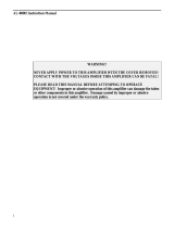
Interconnection Wiring
Basic Interconnect
Basic Interconnect with Radio Interface Cable
Interconnect with Tuner and no KEY LOOP

Version 2
15
Interconnect using KEY LOOP
Interconnections Figure 1

Version 2
16
Amplifier Rear Panel
50VDC The power supply should be unplugged before installing or removing this
connector. This connector is indexed by a slight vertical offset in the two round
index pins. Mate the round pins and holes. Seat the male plug fully onto the
amplifier rear panel male connector pins. After seating, the power supply can be
plugged into the AC mains outlet.
ALC Optional connection. Connects to radio ALC input.
RELAY Connect to radio amplifier keying line. Radio must pull this line below 2 volts to
transmit.
KEY LOOP Output for remote tuner use.
KEY LOOP Switch Switch to turn on and off the KEY LOOP function.
GND Connect to station ground buss, if available. This connection is primarily for extra
safety.
RF IN Connect through good 50-ohm coaxial cable of any reasonable length to radio’s
antenna output connector. This can be a smaller cable, such as RG-58/U.
RF OUT To 50-ohm antenna, antenna tuner, power meter. This is the high power output.
50-ohm coaxial cable and system beyond must safely handle at least 1200-watts.
RADIO INTERFACE This connector is for use with Ameritron radio interface cables. It allows
automatic band selection (following the radio). It also provides amplifier
actuation in transmit mode with some radios.
REMOTE These RJ45 connectors are for an Ameritron remote control head, or remote
operation with an interface box. It provides access to controls, including most
metering functions.
1.) If you use a desktop grounding buss system, connect the station ground buss to the
amplifier rear panel wing nut. National safety codes require the station ground
electrically bond to the power mains safety ground at the building entrance. Do not
connect the amplifier to its own isolated ground rod or ground system.
2.) Connect the power supply to the amplifier.
3.) Connect the RELAY line to the transceiver’s amplifier control port. This port is usually
described or defined in the amplifier interfacing section of the radio or transceiver
manual. This port must pull low for transmit, and be open circuit when receiving. Relay
control voltage from the ALS-1306 is 12 volts positive with only 15 mA current. You
should always check your transceiver’s manual, but almost any standard transceiver
directly interfaces with this amplifier.
4.) Connect the RF OUT (output) port to the appropriate point in your station. This is the
high power RF output cable. This connection would go to your 1500-watt rated
Power/SWR meter, antenna, or antenna matching device. Good quality Mini-8 or RG-8X
cables are acceptable for anything but RTTY use, although larger RG-8 style cables are
normally preferred. Your antenna matching system, or antenna tuner, must connect to
this port.

Version 2
17
5.) Connect the IN connector to your transceiver. Do not install any active antenna matching
devices on this port. In general, the shortest and most direct cable connection is best,
although high quality cables can be very long without adverse effect on performance.
RG-58/U or Mini-8 (RG-8X) style cables are acceptable. You should never use a tuner
of any type on the amplifier input, nor should you drive this amplifier with over 100
watts peak envelope power. Never use a non-FCC accepted device with this amplifier.
6.) The ALC line is optional. In general, transceiver internal ALC is all that is necessary. The
ALC monitors the RF output power and reflected power supplied by the ALS-1306 to the
load.
7.) Operate the bandswitch manually during initial testing. Do not connect band decoders,
band data lines, or computer interfaces until initial tests are completed and the amplifier
is functioning normally.
8.) When using an automatic antenna tuner that has the capability to inhibit the amplifier
from operating either during tuning or when conditions are outside of the tuner’s
capability; and when the radio interface has the Amplifier Relay line included (not using
the RELAY jack); the KEY LINE can be used. The KEY LOOP Switch is used to route
the key signal from the interface to the amp directly or out the KEY LOOP jack.
a. If the KEY LOOP is not used set the KEY LOOP Switch to OFF so the Radio
Interface Cable can key the amplifier.
b. If the KEY LOOP is used with an automatic antenna tuner switch the KEY LOOP
Switch to ON, run a cable from the KEY LOOP connector on the amp to the
AMP ENABLE IN connector on the tuner, and run a cable from the AMP
ENABLE OUT connector to the RELAY connector on the amp.
Optional Radio Interface Cables
ALS-1306/RCS-12 Radio Interface Cables available from Ameritron.
Model No. Description Notes
DB-13D ICOM with ACC, 13-Pin DIN
DB-7DI ICOM with ACC 2, 7-Pin DIN
DB-DB7DK
Kenwood with DB9 (except TS-
480)
SET Baud RATE 9600
590 menu 53 (HF) 54 (50 MHz) #2,
570 menu 39 (HF) and 40 (50 MHz)#2
990 s menu 11 (HF) and menu 12 (50 MHz)
set to 3= active high+relay+delay
2000 menu 28A #2
DB-DB8MK Kenwood TS-480
Baud rate 9600, menu 28 (HF) channel 2 and
29 (50 MHz) channel 2
DB-8MY2
Yaesu FT-
897/857/817/840/890/990/100
DB-8DY
Yaesu with standard 8-Pin DIN
Band Data
DB-10MY Yaesu FT-450/950/1200
DB-DB15Y Yaesu FT-DX3000
DB-DB15HE Elecraft

Version 2
18
Front Panel
Amplifier Front Figure 2
The front panel contains the following indicators and controls. To prevent damage, become
familiar with the front panel before operating the amplifier.
1 FET module current meters
2 Forward Power meter and Multimeter (reflected power, module RF balance, ALC,
and Module supply voltages) selected by knob 7.
3 Band or REMote selector knob.
4 Backlit Band or REMote LED indicators.
5 ALC limit adjustment.
6 Backlit Function and Fault Warning LED indicators.
7 Meter 2 multimeter scale function selector knob.
8 Operate and Standby switch, also resets fault warnings.
9 Main Power, also resets power supply overload.
Note: The right-hand meter’s left scale-arc (fig.2 ref 2A) continuously indicates forward peak envelope
power (PEP) output directly in kilowatts. It is 100 watts, or 0.1 kW, per meter scale picket. PEP has no
fixed relationship to long-term average power except, for constant amplitude carriers like a steady CW
carrier, when PEP and average powers are equal. PEP is the highest average power during one (or more)
radio frequency cycle(s) at the modulation envelope crest.
The right-hand meter’s rightmost scale-arc is used for PEP reflected power in watts and combiner
imbalance on the upper scale numbers and pickets. Notice power meter calibrations are not evenly
spaced. Lower scale numbers and pickets are evenly spaced, and are for other functions. The lower right
scale is used for relative ALC setting and power amplifier modules HV (0-70 volts).

Version 2
19
Operation
This amplifier covers all Amateur Radio frequencies below 54 MHz, as restricted by FCC or
your local governing authority. Once you have established proper connections, please set the
amplifier (Fig. 2, ref 3) to one of the following bands:
Band Frequency Range Notes
160 1.8 - 2.1 MHz
80 3.2 - 4.2 MHz
40 6.0 - 7.5 MHz
30 7.5 - 14.5 MHz USA 30-meter power limit currently 200-watts
20 7.5 – 14.5 MHz
17 14.5 – 22.0 MHz
15 14.5 – 22.0 MHz
12 22.0 – 30.0 MHz Amplifier automatically disables above 25 MHz
10 22.0 – 30.0 MHz Amplifier automatically disables below 28 MHz
6 50.0 – 54.0 MHz
Frequency Limits Table 1
Caution: This amplifier has an FCC mandated automatic disconnect and other features
preventing 27-MHz operation. There is no available circuitry or control provision to circumvent
this lockout.
MARS or CAP Operation
For licensed amateur radio operators participating in Military Affiliate Radio Systems or CAP,
this amplifier is suitable for use on all frequencies between 1.8 and 54 MHz with some
precautions. The upper frequency limits are in bold type in the table above. Do not operate above
the bold-type frequency limits in the table above or PA (power amplifier) or filter damage may
occur.
Ameritron guarantees to exceed FCC part 97.307 harmonic suppression standards, as of January
2013, inside amateur bands listed in the table above. Ameritron does not guarantee harmonic
suppression or operation outside amateur bands. Most commercial services prohibit use of non-
commercial radio equipment.
This amplifier is inoperable between 25 and 28 MHz. Modifications allowing operation in the
25-28 MHz range is not available, irrespective of licensing or end-use.

Version 2
20
Warning Lights
The ALS-1306 has three primary warning lights in the center of the front panel. It also uses other
standard LED’s as warnings, flashing them in a certain code that indicates problems. These lights
serve the following functions:
ALC: The yellow ALC light indicates ALC output. Flashing is normal when using ALC. A
steady intense light indicates a problem.
Operational faults reset by placing the amplifier in standby. The following table applies to faults:
Warning
light
Steady
Warning
light Flash
Fault Cause or Cure
SWR TX
Antenna Reflected
Power
High antenna SWR or
intermittent antenna or feed line
connection
SWR, PA Band
Wrong filter Exciter or amplifier on
incompatible band, filter failure
PA TX
PA FET too hot Excessive power for duty cycle
or SWR, lack of proper airflow
PA Combiner unbalance
10M, PA,
TX
Illegal 11 meter Excessive 27 MHz signal level
REM, PA
No or wrong band when
on remote
Defective or improper remote
cable, or bad radio band data
information
Initial Operation
For your personal and equipment safety, double-check all wiring and connections (fig. 1) before
turning power on. After you have verified amplifier connections, follow the procedures below.
The following steps are necessary during initial checks:
1. Place the MULTIMETER switch (fig.2 ref 5) in the HV2 position. Place the ALC SET
control (fig.2 ref 4) full clockwise (10 on knob scale). The multimeter is the right-side
scale on the rightmost panel meter (fig.2 ref 5).
2. With the STANDBY/OPERATE switch (fig.2 ref 7) on STANDBY, turn the power
switch (ref 8) ON.
3. There will be a slightly delayed “click” from the power supply. HV2 (fig.2, ref 2) should
immediately rise to near full scale, and after a slight delay, you should hear another
“click”. The meters and the appropriate BAND LED (fig.2, ref 3) should illuminate.
4. The multimeter HV2 scale (fig.2, ref 2, bottom right scale) should read between 45 and
55 volts.
5. Change the meter switch (fig.2 ref 6) to HV1. The voltage should be the same as in step
4.
/