Page is loading ...


OPERATOR'S MANUAL
LINEAR AMPLIFIER

0
R.
L.
DRAKE COMPANY
1979
PRINTED
IN
U.S.A.

TABLE
OF
CONTENTS
..
-~
.
PAGE
...................................
...................
CHAPTER
1
INTRODUCTION
,
1-1
...............................................
1-1 GENERAL DESCRIPTION 1-1
..................................................
1.2
.
MANUAL COVERAGE 1-1
........................................................
CHAPTER
2
INSTALLATION 2-1
2.1
. UNPACKING
...........................................................
2-1
..................................................
2.2 . TUBE INSTALLATION 2-1
2.3
.
LOCATION
.............................................................
2-1
...............................................
2.4
.
POWER REQUIREMENTS 2-2
...............................................
2.5 . JUMPER CONNECTIONS 2-2
............................................
2.6 . ANTENNA REQUIREMENTS 2-2
.....................................................
2.7 . LOW PASS FILTER 2-2
.................................................
2.8 . MATCHING NETWORK 2-2
.............................................
2.9
.
GROUND REQUIREMENTS 2-2
..............................................
2-1
0
.
EXCITER REQUIREMENTS 2-2
..................................................
2-1
1
. TRANSMITTING AGC 2-2
.......................................................
..
2-1
2
. VOX RELAY .-. 2-3
r
-
4PTER
3
OPERATION
...........................................................
3-1
..............................................................
3.1 . GENERAL 3-1
.................................................
3.2
.
TUNING PROCEDURE 3-1
3.3
.
CW AND RTTY TUNING
................................................
3-1
3.4
.
SSB AND AM TUNING
.................................................
3-1
3.5
. OPERATION ........................................................... 3-3
............................................
3.6.' CW AND RTTY OPERATION 3-3
.......................................................
3.7
.
SSB OPERATION 3-3
.......................................................
3.8 . AM OPERATION 3-3
...................................................
3.9 . SWR CALCULATION 3-3
3-1
0
. OPERATION ON ACCESSORY FREQUENCIES
..........................
3-4
...............................................
CHAPTER
4
THEORY OF OPERATION
4-1
4.1
. INPUT
.................................................................
4-1
..................................................
4.2 . TRANSMITTING AGC 4-1
...............................................
43
.
STANDBY CUTOFF BIAS 4-1
4.4
.
OUTPUT
...............................................................
4-1
4.5
.
WATTMETER ........................................................... 4-1
........................................................
CHAPTER
5
MAINTENANCE 5-1
.........................................................
5.1
.
SERVICE DATA 5-1
.....................................................
5.2
.
PARTS ORDERING 5-1
.............................................
5.3
.
AMPLIFIER DISASSEMBLY 5-1
.............................................................
5.4 . CLEANING 5-1

PAGE
....
TUBE REPLACEMENT..
..............................
5-1
..............
TEST EQUIPMENT
...................................
5-1
AMPLIFIER TROUBLESHOOTING
...................................
5-2
.................
TUBE CHECK..
..................................
5-2
...
ALIGNMENT PROCEDURES..
,
...................................
5-2
INPUT
COIL ADJUSTME
..................................
5-3
METER ADJUSTMENT
......
.......................................
5-3
WATTMETER CALIBRATION,
............................
...
.......
5-3
............
NULL ADJUSTMENT
..................................
5-3
300 WATTS REFLECTED
...............................................
5-3
300 WATTS FORWARD
..................................................
5-3
3000 WATTS FORWARD
................................................
5-4
KNOB POINTER ALIGNMENT
..........................................
5-4
POWER SUPPLY CIRCUIT BREAKER RESET..
..........................
5-4
REMOVING THE BOTTOM COVER
.....................................
5-4
REMOVING TOP COVER
...............................................
5-4
POWER SUPPLY TROUBLESHOOTING
.................................
5-4

LIST
OF
ILLUSTRATION'S
Figure
1-1
2-1
Page
--
i
i
.
.
MODEL L7 LINEAR AMPLIFIER
..................................
1-2
:'-
.z.
REAR CHASSIS CONNECTORS
..................................
2-4
5-'
JUMPER CONNECTIONS FOR 120 VOLT OPERATION..
...........
2-5
:'
JUMPER CONNECTIONS FOR 240 VOLT OPERATION..
...........
2-5
,
CONNECTING THE PS-7 POWER SUPPLY AND THE
R.
L.
DRAKE
LINE OF COMPATIBLE EXCITERS
......................
2-6
......................................
VIEWING ANGLE OPTIONS 2-7
...............
....................
FRONT PANEL CONTROLS
L..
3-2
PLATE VOLTAGE AND PLATE CURRENT VS 1,000 WATTS
.............................................
DC INPUT POWER 3-5
..............................................
SWR NOMOGRAPH
3-5
..........................
COMPONENT LOCATIONS, TOP VIEW.. 5-5
.....................
COMPONENT LOCATIONS, BOTTOM VIEW.. 5-6
CONNECTIONS FOR
GRID CURRENT METER
....
--
-
..->.r
..
~;
-
-
..
.....
..........................................
CALIBRATION
.,
5-7
............
MODEL L7 POWER SUPPLY SCHEMATIC DIAGRAM.. 5-7
.........
MODEL L7 LINEAR AMPLIFIER SCHEMATIC DIAGRAM.. 5-9


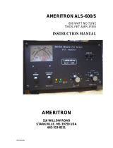
1-1.
GENERAL DESCRIPTION
TheR
L.
Drake Model L
7
Linear Amplifier offers
con.tinuoas 2000 Watts PEP on SSB, and 1000
Watts
DC
on CW,
AM
(controlled carrier) and
RTFY
operation covering the ham bands 160
through
15
meters. Non-amateur frequencies
between
1.8
and
21.5
MHz
may be covered with
mdi5cation of the input circuit.
The
L7
uses
2
zero-bias triodes in a Class
B
gmunded-grid circuit configuration that utilizes
RF
negative feedback for lower odd-order distor-
tion products.
As
shipped from the factory, these
tubes
will
be
one of the following listed parts,
which
are interchangeable but which are fur-
nished
in
pairs only:
Amperex 8802/3
-
5002
Amperex
8163
Eimae
3
-
4002
Eimac 3
-
5002
The
tnbes
are cooled by a quiet, dual-speed inter-
nal
&we.
A
transmitting AGC circuit controls the exciter
gain
to
allow the highest average power without
peak
clipping. Aninternal changeover relay feeds
CHAPTER
1
INTRODUCTION
the antenna through when theL
7
is
turned off. A
pair of relay
contacts bias the output tubes
to
cut-
off, eliminating unwanted
heat
and diode noise
when receiving. Twometers indicate plate
current,
grid current, plate voltage,
RF
output power, and
RF reflected power. The separate solid state Power
Supply requires no warm-up
period
and provides
excellent dynamic and static
vol-e regulation.
1-2.
MANUAL COVERAGE
This manual
is
presented
in
5
chapters with sup-
porting illustrations and is arranged for the con-
venience of the operator and
service
technician as
follows:
Chapter
1
Introduction (self explanatory).
Chapter
2
Installation. Describes the procedure8
to
be followed prior
to
operation.
Chapter
3
Operation. Illustrates and describes
front panel controls and describes
tune-up and operation
in
SSB, CW,
RTTY, TUNE and
AM
modes.
Chapter
4
Theory of Operation. Describes all
critical circuits and networks.
Chapter
5
Maintenance. Provides maintenance
instructions, troubleshooting and
parts ordering information.

'
Fig.
1-1
Model
L7
Linear
Amplifier
6
.>-
SPECIFICATIONS
Frequency Coverage: Ham bands
160
through
15
meters. Non-amateur
fre-
quencies between
1.8
and
21.5
MHz may be covered
with some modification of
the input circuit.
Plate Input:
2000
Watts PEP on SSB
and
1000
Watts DC on CW,
AM
and RlTY.
Drive Requirements:
100
Watts PEP on SSB and
75
Watts on CW,
AM
and
nmr
IbLLI.
Input Impedance:
50
Ohms (Band Pass Tuned
Input),
Output Impedance: Adjustable pi-network
-
matches
50
ohm line with
SWR not
to
exceed
25.
Intermodulation
'
'
Distortion Products In excess of
-33
dB.
Wattmeter Accuracy:
300
Watts forward and re
flected,
*
(5%
of reading
+
3
Watts).
3000
Watts forward,
*
(5%
of reading
+
30
Watts).
Power Requirements:
240
Volts
50-60
Hertz
15
Amperes, or
120
Volts
50-60
Hertz
30
Amveres.
Tube Complement:
Two of
3-5062
or
8802/3-
.5002
or
8163
or
3-4002.
-
-
.
-
- - -
Dimensions:
Amplifier
1*11/6
in. W x
6-3/4
in. H
x
14-1/4
in. D.
(34.8
cm W
x
17.1
cm H x
36.2
cm D.)
Power Supply
6-3/4
in.
w
x
7-7/8
in. H
x
11
in.
D.
(17
cm
.
Wx20cmHx28cmD.)
Weight:
Amplifier
-
27
lbs.
(12.25
kg.)
Power Supply
-
42.5
lbs.
Q9.3
kg.)
*
Export model includes coverage of
10
meter Ham
Band.

WARNING
The
L
7
has been designed incorporating several
interlocks to prevent dangerous electrical shock.
However,
it
is possible to disconnect the high
voltage terminal while the
L
7
is turned on. This
is
EXTREMELY DANGEROUS
and never
should be attempted for
am reason. When dis-
assembling the
L
7,
the high voltage terminal
should
be
disconnected
LAST
and at reassembly
the high voltage terminal should be connected
FIRST.
The
L
7
and its Power Supply can be
installed and serviced in complete safety
if
the
instructions in this manual are followed ex-
plicitly.
''
2-1.
UNPACKING
The
L
7
Linear Amplifier is shipped from the fac-
tory
in
3
separate cartone;
1
contains the Ampli-
fier,
1
contains the Power Supply and the third
contains the tubes and the miscellaneous hard-
ware.
Carefully unpack all three cartons and
examine
their contents for evidence of shipping
damage. If any damage
is
discovered, notify the
transportation company that delivered the
equip-
ment.
Be
sure to keep the cartons and packing
material
as
the transportation company
will
want
to examine them. Keep the carton and
packing
even
if
no shipping damage occurs. Having the
original
cartups available simplifies repacking
the equipment for storage or to return
it
to the
factory for service. Inspect the packing material
closely before storing
it
to be sure that none of the
accessory hardware has been overlooked. The dis-
mounted components and accessory hardware
shipped
with
the
L
7
should be checked against
the following list.
a. 2 tubes (Amplifier
V1
and V2)
b
.
2
Plate Caps (for Tubes)
c. (2)
632x518 screws (for Plate Caps)
d
.
2
Parasitic Chokes (Note TOP label)
e.
(2)
6432x114 Screws (connect Chokes to Caps)
f.
2
Internal Tooth Lock Washm (connect
Chokes
to
Caps)
g
.
2
Cables (1 Vox Relay,
1
Transmit
AGC)
h.
1
Plug,
%Pin
(Vox Relay)
i.
2 Resistors, 0.82 Ohm,
2
Watts (&placement
spares for Power Supply
R12)
j
.
2
Rubber Feet (For Viewing OptionB)
k.
2
studs (to attach rubber feet)
CHAPTER
2
INSTALLATION
1
.
1
Instruction
Manna1
(READ
ZF)
m.
1
Warranty F&gi&ration
Card
Nrn
EFll
out the enclosed
Warranty
Regidrdon
card
and
return
it
to the
~ryhnediately
to
insue
-tion
and validation
of
the
warran*.
2-2.
TUBE INSTALLATION
WARNING
Tubes
must
beMed
and thecabinetreplad
BEFORE
ANY
CO~ONS
are
made
to
the
L
7.
a. Remove the
6
screws
which
secure
the cabinet
to the amplifier and remove
the
cabinet
b. Refer to
fignre+L
Insert
both
tobes
into
the
sockets on the amplifier
ehassia
Note the pin
arrangement:
Pin
3
is
isola6ed.
c.
Install
the
plate
caps
on the
tubes
and secure
them
with
the scsews provided.
d. Attach the parasitic chokes to the top of each of
the plate
caps
with
the
screws
and
loekwashers
provided. Make
sure
that the
coils
of the two
chokes hang
DOWN.
The
word
TOP
stamped
on each choke musk
be
visible from the top of
the amplifier.
e. Attach both of
theremaining leads onthepara-
sitic chokes
to
the top
of
the
plate
RF
choke
using the
1/420
alnmmmn
screw
which
also
secures one lead from the coupling capacitors.
DO
NOT
wertighten this screw.
f.
Replace the cabinet and
secure
it
with the
6
screws removed
in
step
a
2-3.
LOCATION
In
general, the location of the
L
7
is
not Critical;
however, there are
certain
considerations which
must be
given
to
insure optimum performance.
Care
should be taken to insure that a space is pro-
vided around the Power Supply case to allow
ade
quate air circulation. Extremely hot
locations,
such as near radiators or heating
units,
should be
avoided. The back of the Amplifier case
must not be obstructed and should not be placed
closer than
1
inch from a wall or the
air
inlet, for
the blower
will
be blocked and overheating of the
tubes may occur.

2-4. POWER REQUIREMENTS
The L 7 is furnished with its own separate Power
Supply which can be operated from either 120
VAC or 240 VAC
50-60 Hertz. Because of the large
variety of plug and socket configurations for 240
volt service, and because the L 7 can be operated
from either 120 Volts or240 Volts, a line plug is not
furnished with the L
7.
TheL 7is shippedfrom the
factory with jumpers connected to operate on 240
VAC. It is highly recommended that the L
7
be
operated from its own 240 Volts (15 Amps or
greater) circuit. If a 120 Volt circuit is all that is
available, it should be fused for 30 Amps and the
circuit conductors should not be less than No. 10.
No other equipment should be operated from this
circuit. DO NOT under any circumstances operate
the L 7 from a 120 Volt lighting circuit because the
circuit conductors are not large enough to carry
this load safely.
2-5. JUMPER CONNECTIONS
Figures 2-2 and 2-3 are diagrams of jumper con-
nections required for 120 and 240 Volt operation.
The jumpers in both the Amplifier and Power
Supply must be connected as shown or serious
damage to the
L
7
components may result.
2-6. ANTENNA REQUIREMENTS
The L 7 has been designed for use with antennas
resonant at the operating frequency and having
approximate impedances within the limits of 25 to
100 Ohms.
T)le nominal output impedance of the
amplifier is 50 Ohms and the SWR of this load
should never exceed
23. Although there are many
types of antennas which will meet these require-
ments, the simplest is a one-half wave dipole
center fed with 52 Ohm coax. For a detailed dis-
cussion on antennas, refer to an appropriate
antenna book.
2-7.
LOW PASS FILTER
The amplifier has been designed in accordance
with good engineering practices, and harmonic
attenuation meets or exceeds current FCC specifi-
cations. Because of the possibility that you may be
qsing a multiband antenna or have afeed line that
is resonant at a harmonic frequency, it is highly
recommended that a suitable low pass filter such
as the
R.
L. Drake Model TV-3300- be used with
the
L
7.
2-8. MATCHING NETWORK
Most practical antennas exhibit an SWR range
over a complete amateur band that exceeds
2:l.
For this reason we recommend using an antenna
matching network such as the R.
L.
Drake
MN-
2700 which will allow the L 7 to work into a 50
Ohm
load for maximum power transfer into the
antenna.
CAUTION
Never attempt to operate the
L
7
without first
connecting to an antenna or 50 Ohm Dummy
Load of sufficient power handling capacity
or serious damage may result.
2-9. GROUND REQUIREMENTS
For best results, the amplifier should be attached
to a good earth ground through as short and as
large a ground strap as possible. A binding post is
provided on the rear of the amplifier chassis for
the ground connection. It is always a good idea to
connect the chassis of all associated equipment
together
and
ground them at one point to avoid
ground loops. We recommend that all of the equip-
ment in your station be connected together and
grounded at the L
7
Amplifier chassis.
2-10. EXCITER REQUIREMENTS
To operate the amplifier at the maximum legal
input the exciter must provide 100 Watts PEP RF
power for
SSB operation and
75
Watts RF power
for CW,
AM,
RTTY and TUNE operation.
Locate the exciter as close to the amplifier as
practical
to
shorten the coaxial cable and ground
strap. Refer to figures 2-4 and 2-5 for recom-
mended connection arrangements.
2-11. TRANSMITTING AGC
The transmitting AGC voltage, which controls the
gain of the exciter, is presented at a connector
labeled XMTG AGC OUTPUT on the rear of the
L
7.
Any power level can be run up to 2000 Watts
PEP without peak
cliGping. A cable is furnished
with the amplifier which provides a connection
to the
R.
L.
DrakePS-7
or AC-4Power
Supply. This
connection
is
routed through the power supply to
the transmitter.

2-12.
VOX
RELAY
Aphono jack on therearoftheL7AmpMerkpm
vided for connection to a
paiT
of norma&
open
relay contacts in the exciter,
which
doseontrans
mit and thus turn on the arnpliik
ar
the
same
time The L7 is supplied
with
a
cable
with
phom,
plugs on each end for
this
pnrpase
AGcand-
PS7 Power Supplies
are
equipped
ui+h
a
-'pin
connector instead of a phono
jackforthis-
tion. A loose two pin plug
is
soppH
ssith
tbeC
accessory kit and
this
plug
must
be
ix&dkd
cm
one end of the cable
in
place
of
the
phmo
when used with
these
models.
For
TR7's and
similar
excbs.
ir
is
w
observe the
correct
polar&
when
tealhe
VOX
RELAY
circuit
If
a
phono
conneebris
aed
this is automaticall3 ammpldud
If
a
tro
pin
connector
is
used.
the
wrred
polarity
is
obginsd
with the folloaiing
pdm
Place
rbe
&in
STANDBY and set the
Li
MODE
switch
to
CX.
the ON/OFF switch
to
Oh',
and the
SlBY
sricefi
in the "operate" (out) position.
Plug
in
rbe
Xi0Z
cable connectors
and
observe the
Plate
-x
Meter. If it reads upscale,
reverse
the
mpinV0X
connector on the exciter end. The ampbfkr
phe
current must be zero with the
V05
cable
in and the exciter
m
STANDBI-.

TYPE
ACCEPTANCE
LABEL
HIGH VOLTAGE
CONNECTOR
J5
.
..
..
~,
. ..
-. .
.:
-
.
-
.
.
<;,i
=
I
J6
--
.
I
;
:
CONNECTOR
I
.I
.
;
L
.
,
e;
-.
n
'
J
4
Fig.
2-1
Rear Chassis Connectors

120 VOLT OPERATION
Amplifier Power Supply
--
~~
~~
--
-
Figure
2-2.
Jumper Connections for
720
Volt Operation
.+
-
-
.
...
.
~
-
..
240 VOLT OPERATION
--
-
-
.. .
..
-.
Amplifier Power Supply
-
---
-
...-
.
-
?
..*
<:
-
..-.
-.+-
.
-
Figure
2-3.
Jumper Connections for
240
Volt Operation
:;
-.
.
I.:
_
~
-
.
-

Fig.
2-4
Connecting the PS-7 Power Supply and the
R.
L. Drake Line of Compatible Exciters

OPTION
A
i
OPTION
B
INVERTED FRONT FEET
mi
SUPPLIED WITH UNIT
SUPPLIED WITH UNIT
Fig.
2-5
Viewing Angle Options

.>
NOTES

CHAPTER
3
OPERATION
CAUTION
DO NOT
turn on the L 7 Amplifier with the
cabinet removed because the high voltage
inter-lock shorts out the
B+ and will damage
Power Supply components.
DO NOT
operate
the Linear Amplifier until
it
has been
connected
to
a 50 Ohm antenna or a 50 Ohm
Dummy Load. Be sure that the correct jumper
connections described in Chapter 2 have
--
been made in both the Linear Amplifier and
-
the Power Supply for the line voltage to be
used.
3-1. GENERAL
Figure
3-1
identifies and describes all front panel
controls and indicators referred
to
in these tuning
and operating procedures. Perform the appro-
priate tuning procedures described below prior
to
operation.
For all modes of operation, the L 7is tuned up with
a single RF frequency driving
it
and
with
the
Mode switch in CW position. The exciter may be
tuned up on CW into the antenna
connected
to
the
amplifier by depressing the
STBY switch. The
exciter should be checked
to
be sure that
itis
tuned
up when driving the L 7 since the antenna
wn-
nected
to
the amplser may not be exactly 50
Ohms.
..
3-2. TUNING PROCEDURE
After the exciter has been tuned up,
turn
the
exciter to standby andrelease
theSTBY switch on
the
L
7.
Set the Mode switch (red rocker switch)
to
CW position. The light that indicates high plate
voltage for SSB operation should be off, and the
OPR light should be on.
The Drake TR
7
and some other exciters utilize
transmitting AGC, sometimes called
ALC, during
all modes of operation. During tune up, transmit-
ting AGC will have
to
be defeated either by un-
plugging the transmitting AGC
connector, or by
turning the AGC control fully counterclockwise.
All Drake Transmitters and Transceivers except
the TR
7
and
2NT
(which has no transmitting
AGC) switch off AGC in
TUNE,
CW and
AM
modes. It is not necessary
to
defeat AGC exter-
nally on Drake Transmitters, other than
theTR-7.
3-3. CW AND RTTY TUNING
Preset the front panel controls on the L
7
as
follows:
a. Mode switch
to
CW.
b. Band switch
to
desired band.
c. Meter switch to
3000
WAm
FWD.
d. STBY switch
to
"operate" (out).
e.
LOAD
fully counterclockwise
to
zero.
f. PLATE wntrol in the arc provided for the
desired band.
g.
Turn
AGC control fully counterclockwise.
h. ON-OFF switch
to
ON.
Turn on the exciter and increase the exciter output
while not exceeding
0.400 Amperes plate current.
Tune the
PLATE
control for a dip in plate current.
Alternately adjust the
LOAD
and PLATE controls
while
increasing
the exciter power in small incre-
ments until maximum
RF
output occurs at 0.565
plate Amperes. Because of variations in line vol-
tage
a
graph (figure
3-2)
is
supplied which corre-
lates plate voltage and plate current for
1000
Watts DC plate input power and should
be
used
to
be sure that the amplifier
is
operating at or under
the maximum legal input power.
In
case maxi-
mum legal input cannot be obtained because of
low exciter power, tune for maximum forward
RF
Watts at maximum exciter power.
3-4.
SSB
AND AM TUNING
Preset the front panel controls on the L7 as
follows:
a. Mode switch
to
CW.
b. Band switch
to
desired band.
c. Meter switch to IG (grid current).
d. LOAD control fully counterclockwise
to
zero.
e
.
Plate wntrol in the arc provided for the desired
band.
f
.
Turn AGC control fully counterclockwise.
g.
STBY switch
to
"operate" (out).
h. ON-OFF switch
to
ON.
NOTE
Substitute
250
mA
grid current for 200
mA
in
succeeding
test
if
'Amperex 8802/%500Z
tubes are installed in the amplifier.
Turn on the exciter and increase the exciter output
while not exceeding
0.400
Amperes plate current
and tune the PLATE control for a dip in plate cur-
rent. While increasing the exciter power, maintain

-
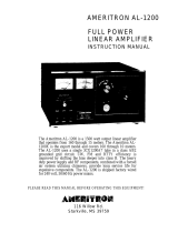
FIGURE 3-1. FRONT PANEL CONTROLS
I.
Multimeter: Indicates plate voltage, grid current, and forward or reflected watts as selected by
meter switches
(8).
2.
Plate Current Meter: Indicates plate current.
3. Indicator Lamps: Indicate standby or operate condition,
SSB (high power) mode, and multimeter
function.
4.
STBY Switch: When depressed, allows standby operation with the exciter connected straight
through to the antenna.
5.
AGC Control: Adjusts the transmitting AGC threshold.
6.
ON/OFF Switch: Turns the main power on and off.
7.
MODE Switch: Selects highplate voltage for SSBoperation or lowplate voltage for CWoperation
oi for tuning.
8.
Meter Switches: Select indication for Multimeter (1).
9.
PLATE Control: Resonates the plate tank circuit.
10.
BAND Switch: Selects input andplate tank components to resonate the amplifier on the selected
band.
11.
LOAD Control: Adjusts the output impedance of the amplifier to match the antenna load
impedance.
-%I.
:
=-.;?
.
..+
-
/