Page is loading ...

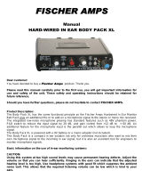
Silo pressure detector
with aluminium housing
Type plate details
CE sign with the number of the "Notified Body"
which is involved in the production control phase
Manufacturer and address
Gas and Dust marking
Ambient temperature
(Operation temperature)
Vessel pressure
(tested pressure)
EU-type examination certificate number
Type of protection
Model designation
Unique serial number
Number which the
order was handled
Month and year of delivery
W
Typ
MSD-A1F1A-B5
IBExU06ATEX1069
Auftrag-Nr. 1234567890
Industriepark RIO 103
D-74706 Osterburken
Tel. +49 62 91 64 400
M LLET
Füllstandtechnik
GmbH
0044
oben top arriba haut
-20 °C € Ta € +70 °C
p -0,08bar...+0,08bar
IP66
Contact U £ 30 V
o
I £ 0,1 A
k
C
NO
NC Connection diagram
Competence in explosion protection
M LLET
and supplement to the operating instructions
Explosion protection information
Gas+Dust and hybrid mixtures
Details of intrisically safe
supply of the signal contact.
M LLET
Füllstandtechnik
GmbH
MOLOS
MSD-A
Gas+
Dust
II 1/2D Ex ta/tb IIIC T 80 °C Da/Db
Stück Nr. 1234567890 03/21
II 2G Ex ib IIC T6 Gb
06/21 © by MOLLET MSDA-EIG-01 01
MOLLET D-74706 Osterburken Tel. +49 6291 6440-0 www.mollet.de Explosion protection information

M LLET
Füllstandtechnik
GmbH
Marking in accordance with ATEX and DIN EN IEC 60079-0
MOLOS
Silo pressure detector
MSD
Equipment category Category 1 for zone 20, 21 and 22
/ = Silo pressure detectors, which are installed
on the boundary between different zones
Category 2 for zone 21 and 22
Equivalent to valid ATEX-Product-Directive
D = Dust - Type of explosive atmosphere
Silo pressure detector for use on the boundary from zone 20 to zone 21.
Equipment group II = everything except mining
W II 1/2 D Ex ta/tb IIIC T80°C Da/Db
t = Protection by enclosure
T..°C maximum surface temperature
IIIC for flammable conductive dust, flammable non-conductive dust and flammable fibres and flyings
a = Device with „very high“ protection standard . . . . for zone 20, 21 and 22
Equipment Protection Level (EPL)
D = Dust - Type of explosive atmosphere
the Ex - symbol according to DIN EN IEC 60079-0
a = Device with “very high level of protection” for use in potentially explosive atmospheres where in
normal operation, foreseeable or infrequent faults/malfunctions no ignition hazard is given.
b = Device with „high“ protection standard . . . . . . . . for zone 21 and 22
b = Device with “high level of protection” for use in potentially explosive atmospheres where in
normal operation or foreseeable faults/malfunctions no ignition hazard is given.
W II 2G Ex ib IIC T6 Gb
Silo pressure detector for use in zone 1.
Equipment category Category 2 for zone 1 and 2
i = Protection by intrisically safe
b = Device with “high level of protection” for use in potentially explosive atmospheres where in
normal operation or foreseeable faults/malfunctions no ignition hazard is given.
Temperature class T6 = 85°C
G = Gas - Type of explosive atmosphere
G = Gas - Type of explosive atmosphere
IIC for all flammable gases
Equipment Protection Level (EPL)
b = Device with „high“ protection standard . . . . . . . . for zone 1 and 2
W II 1D Ex ta IIIC T 80 °C Da
200
Silo pressure detector for use in zone 20.
Equipment category Category 1 for zone 20, 21 and 22
Equipment category Category 1 for zone 0, 1 and 2
i = Protection by intrisically safe
a = Device with „very high“ protection standard . . . . for zone 0, 1 and 2
Silo pressure detector for use in zone 0.
W II 1G Ex ia IIC T6 Ga
02 MSDA-EIG-02 08/21 © by MOLLET
Explosion protection information MOLLET D-74706 Osterburken Tel. +49 6291 6440-0 www.mollet.de

zone 20 zone 21
M LLET
Füllstandtechnik
GmbH
T 80°C
008-0300
D p =
-0,08 bar...+0,08 bar
W
Typ
MSD-A1F1A-B5
IBExU06ATEX1069
II Ex ta/tb IIIC Da/Db 1/2D T 80 °C
Stück Nr. 1234567890 01/11
Auftrag-Nr. 1234567890
Industriepark RIO 103
D-74706 Osterburken
Tel. +49 62 91 64 400
M LLET
Füllstandtechnik
GmbH
0044
oben top arriba haut
-20 °C € Ta € +70 °C
p -0,08bar...+0,08bar
IP66
II Ex ib IIC Gb 2G T 6
Contact U £ 30 V
o
I £ 0,1 A
k
C
NO
NC
W
Typ
MSD-A2F1I-B22
IBExU06ATEX1069
II Ex ta IIIC Da 1D T 80 °C
200
Stück Nr. 1234567890 01/11
Auftrag-Nr. 1234567890
Industriepark RIO 103
D-74706 Osterburken
Tel. +49 62 91 64 400
M LLET
Füllstandtechnik
GmbH
0044
oben top arriba haut
-20 °C € Ta € +70 °C
p -0,08bar...+0,08bar
IP66
II Ex ia IIC Ga 1G T 6
Contact U £ 30 V
o
I £ 0,1 A
k
C
NO
NC
008-0301
zone 1
Ta =
-20 °C ... +70 °C
T 80°C
D p =
-0,08 bar...+0,08 bar
Ta =
The device can be installed in
the walls of vessels with
deviating atmospheric conditions
with a difference in pressure up
to Dp 80 mbar at the membran.
The device can be installed in
the walls of vessels with
deviating atmospheric
conditions with a difference in
pressure up to Dp 80 mbar at
the membran.
Marking: II 1D / 2D
(the air or the bulk goods temperature) nearby the device.
The maximum surface temperature means the hottest point at the equipment.
Order code B5
II 2G
Ambient temperatures Ta
The device matches with temperature class T 6.
the detectors. Inside the vessel this is process temperature
maximum surface temperature T
Equipment category appropriation by zones
Silo pressure detector for use in zone 1 and at the boundary from zone 20 to zone 21.
The ambient temperature Ta defines the maximum operating temperature of
Order code B22
Marking: II 1D
II 1G
The ambient temperature Ta defines the maximum operating temperature of
(the air or the bulk goods temperature) nearby the device.
maximum surface temperature T
Ambient temperatures Ta
The maximum surface temperature means the hottest point at the equipment.
The device matches with temperature class T 6.
Equipment category appropriation by zones
Silo pressure detector for use in zone 0 and zone 20.
the detectors. Inside the vessel this is process temperature
Gas+Dust and hybrid mixtures
Gas+Dust and hybrid mixtures
z
o
n
e
20
z
o
n
e
0
-20°C
...
+70°C
MOLOS
Silo pressure detector
MSD
06/21 © by MOLLET MSDA-EIG-03 03
MOLLET D-74706 Osterburken Tel. +49 6291 6440-0 www.mollet.de Explosion protection information

M LLET
Füllstandtechnik
GmbH
Special conditions and instructions for safe application
cable has to be brought into the cable gland.
3. Take notice of the specifications on the data plate.
4. ATTENTION! with design B5:
be connected in series, witch is certified for gases of explosion group IIC.
1. The installation, maintenance, initial operation, removal and repair have to be controlled resp. checked by an “authorized person” for
explosion protection.
For load limitation a certified barrier or a certified isolation amplifier with an intrinsically safe circuit at least for the category “ib” has to
2. For the electrical connection you have to take notice of the local and statutory requirements and/or the VDE 0100.
4. ATTENTION! with design B22:
For load limitation a certified barrier or a certified isolation amplifier with an intrinsically safe circuit at least for the category “ia” has to
be connected in series, witch is certified for gases of explosion group IIC.
5. As soon as the device will be brought into the explosion hazardous area it has to be mounted immediately at the precaused place and a
temperatures and follow the pertinent rules and regulations.
16. The device with an intrinsically safe electric circuit can be used in dusty explosive hazardous areas.
9. The earth connection of the device has to be installed in such a way that mechanical damage will be excluded.
17. Hybrid Mixtures
mounting or at the transport. When it is loosened, it ha s to be fitted again.
If it will be fastened too strong, the IP-protection can be affected.ATTENTION!
11. Switch off the power supply, before opening the device.
10. The device may put into operation with intact cap-sealing and when it is closed, only.
+300 °C (BAM assessment), the parts in contact with the dust musst be made of stainless steel.
14. In zone 0 all parts in contact with gas and dust must be made of stainless steel.
15. Take notice of the requirements of DIN EN 60079-14, DIN EN 60079-17 and DIN EN 1127-1, especially regarding the dust deposits and
7. The cable gland and the plug screw were screwed and protected at the factory. Please check if they have loosened during on the
8. To secure the type of protection, the screw nut of the cable gland has to be fixed at the installation with a torsional force of min. 5.0 Nm.
12. Using the Silo pressure detector in the silo wall under deviating atmospheric conditions the maximum differential pressure has not to
13. In case of existing combustible dusts with a minimum ignition energy less than 3 mJ or with a minimum ignition temperature under
exceed 80 mbar and the working temperature has not to exceed +80 °C at the membran.
6. Using the device in ambient temperatures > +60 °C, the applied connection cables have to be made for temperatures of min. +80 °C.
18. ATTENTION safety device!
Don´t modify anything at the device or at the switching point adjusting!
_
The Silo pressure detector is approved for the use in hybrid mixtures.
MOLOS
Silo pressure detector
MSD
04 MSDA-EIG-04 06/21 © by MOLLET
Explosion protection information MOLLET D-74706 Osterburken Tel. +49 6291 6440-0 www.mollet.de
/