Page is loading ...

M LLET
Füllstandtechnik
GmbH
MOLLET D-74706 Osterburken Tel. +49 6291 6440-0 Fax +49 6291 9846 Operating instruction
04/13 © by MOLLET SES-BAD-01 01
Swivelling lever
with limit switch
Operating instructions
Page
Index
Dust
Safety instructions . . . . . . . . . . . . . . . . . . . . . . . . . . . . . . . . . . . . . . . . . . . . . . . . . . . . . . . . . . . . . . . . . . . . . . . 02
Operating instructions
1. Specification . . . . . . . . . . . . . . . . . . . . . . . . . . . . . . . . . . . . . . . . . . . . . . . . . . . . . . . . . . . . . . . . . . . . . . . . . . 03
1.1 Intended use
1.2 Function
1.3 Technical Data
1.4 Materials
1.5 Dimensions
2. Installation . . . . . . . . . . . . . . . . . . . . . . . . . . . . . . . . . . . . . . . . . . . . . . . . . . . . . . . . . . . . . . . . . . . . . . . . . . . 03
2.1 Preparation
2.2 Mechanical connections
2.3 Electrical connection . . . . . . . . . . . . . . . . . . . . . . . . . . . . . . . . . . . . . . . . . . . . . . . . . . . . . . . . . . . . . . . . . . . . . 04
3. Utilization . . . . . . . . . . . . . . . . . . . . . . . . . . . . . . . . . . . . . . . . . . . . . . . . . . . . . . . . . . . . . . . . . . . . . . . . . . . . 04
3.1 Putting into Operation
3.2 Normal Operation
3.3 Inexpert Handling
4. Maintenance and servicing . . . . . . . . . . . . . . . . . . . . . . . . . . . . . . . . . . . . . . . . . . . . . . . . . . . . . . . . . . . . 04
4.1 Maintenance
4.2 Servicing
5. Storage . . . . . . . . . . . . . . . . . . . . . . . . . . . . . . . . . . . . . . . . . . . . . . . . . . . . . . . . . . . . . . . . . . . . . . . . . . . . . . 04
6. Disposal . . . . . . . . . . . . . . . . . . . . . . . . . . . . . . . . . . . . . . . . . . . . . . . . . . . . . . . . . . . . . . . . . . . . . . . . . . . . . 04
SES

M LLET
Füllstandtechnik
GmbH
02 SES-BAD-02 10/21 © by MOLLET
Operating instruction MOLLET D-74706 Osterburken Tel. +49 6291 6440-0 Fax +49 6291 9846
1. Safety instructions
For the application of limit switches in explosive hazardous areas
1.1 The installation, initial operation and maintenance may be done by a qualified expert with electrical know-how only
and has to be supervised resp. controlled by an “authorized person” for explosion protection.
1.2 Comply with the local and statutory rules and regulations and/or the VDE 0100.
1.3 .Before electrical connection, compare the supply voltage with the details at the data plate
1.4 The swivelling lever has to be constantly conductible connected to the electrically conductive, earthed tubing.
- If the tubing is not electrically conductive the swivelling lever has to be earthed.
1.5 The pipeline must not be made of aluminum, titanium or zirconium.
1.6 A fuse (with max. 4 A) has to be connected in series to the supply voltage.
1.7 .Protect the signal contacts of the limit switch against voltage peaks when inductive loads are connected
1.8 Take notice of the requirements of DIN EN 60079-14, DIN EN 60079-17 and DIN EN 1127-1, especially regarding the dust
deposits and temperatures and follow the pertinent rules and regulations.
1.9 .The swivelling lever with limit switches can be used in areas classified as zone 22
1.10 Temperatures
Read and follow these safety instructions first and take notice of the operating instructions.
! SES
Ambient temperature -20 °C ... +60 °C
maximum surface temperature T 80 °C
Dust
Swivelling lever
with integrated
limit switch
SES

M LLET
Füllstandtechnik
GmbH
MOLLET D-74706 Osterburken Tel. +49 6291 6440-0 Fax +49 6291 9846 Operating instruction
04/13 © by MOLLET SES-BAD-03 03
011-0218
max. 215
128
265
210
10 x 40
011-0700
011-0701
10 - 25
Operating instruction
1. Specification
1.1 Intended use
The swivelling lever with limit switch is for signalizing that a hose
coupling has been coupled at silos or tanks or coupling stations.
1.2 Function
While coupling the counter coupling or hose coupling the lever is
swivelling beside and the limit switch will be actuate.
1.3 Technical data
Manufacturer MOLLET
Füllstandtechnik GmbH
Address Industriepark RIO 103
74706 Osterburken
Name Swivelling lever with limit switch
Type SES ... B0
Weight 3 kg
Nominal size 065 for tube Æ 76.1
080 for tube Æ 88.9
100 for tube Æ 108 ... 114.3
125 for tube Æ 133 ... 139.7
150 for tube Æ 159 ... 168.3
Cabel length 2 2 meter cabel
5 5 meter cabel
0 10 meter cabel
1.4 Materials Fixing plate Steel, galvanized
Swivelling lever Steel, galvanized
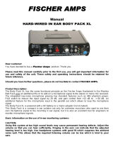
1.5 Dimensions
2. Installation
2.1 Preparation
Read and follow the safety instructions and the operating
instructions, before handling with the device !
2.2 Mechanical conections
- Place the pipe shackle over the tube and into the borings of the
fixing plate.
- Set the nuts and washers at the pipe shackle.
- Screw them tightly on.
- Align the swivelling lever as shown in the drawing below with a
distance of about 10 up to maximum 25 mm to the coupling.
- Check whether the lever can be swivelled out without obstruction.
- In case of slanting or horizontal pipe always fasten to the upper
side. The lever must fall into the final position shown in the drawing
by virtue of its own weight.
- Screw the both nuts so that the two threaded ends are about the
same length.
- Now put the cap nuts on and screw them tightly.
Swivelling lever
with integrated
limit switch
SES

M LLET
Füllstandtechnik
GmbH
04 SES-BAD-04 08/22 © by MOLLET
Operating instruction MOLLET D-74706 Osterburken Tel. +49 6291 6440-0 Fax +49 6291 9846
2.3 Electrical connection
SES - Limit switch with mechanical contact
Matreial Switch Zn-Al alloy
Switching voltage 10 ... 250 V AC or DC
Switching function 1 NC + 1 NO
Capacity of the contact max. 1.5 A / 250 V AC
Ambient temperature -20 °C ... +60 °C
Type of protection IP67/IP66 acc. DIN EN 60529
Ex type of protection B0 W II 3D Ex tc IIIB T 80 °C Dc
Connection diagram
Lay a loop at the swivelling lever to compensate the
swivelling movement.
BK
sw
bl
BU
sw/ws
BK/WH
gr/ge
GN/YE
BN
br
011-AP00
011-0701
3. Utilization
3.1 Commissioning
Put the swivelling lever into operation only, if the installation and
the electrical connection have been done correctly.
3.2 Normal operation
- Use the swivelling lever in its intended application only.
- Comply with the specifications on the data plate.
3.3 Inexpert handling
- Ignoring the safety instructions and the operating instructions.
- Not intended use.
- Mounting of spare parts which are no original parts.
- Violation against applicable law and standards.
-
4. Maintenance and Servicing
4.1 Maintenance
Inspect the swivelling lever about cleanness and smooth
engagement in regular intervals. Define the intervals of the control
depending on the ambient conditions and the frequency of use.
4.2 Servicing
- Carry out repairs only when the swivelling lever is disconnected
from the electrical supply before.
- Damaged parts have immediately replaced with similar.
- Until the complete restoration of the proper function the swivelling
lever must not be used any more.
- Use original spare parts only.
-
5. Storage
- Store the swivelling lever dry and dust-free.
-
6. Disposal
- The swivelling lever can be recycled.
- The disposal applies to the valid environmental guidelines
according to the location of the carrier and the local manufacturing
conditions.
-
Swivelling lever
with integrated
limit switch
SES
/