Page is loading ...

Bulk good temperature -25 °C ... +80 °C
Type MSD-A . F1 .
Ambient temperature -20 °C ... +70 °C
1.3 Technical data
Manufacturer MOLLET
Capacity of the contact 4 A / 250 V AC
Füllstandtechnik GmbH
74706 Osterburken
Switching voltage 24 V ... 250 V AC
Name Silo pressure detector
or 12 V ... 125 V DC
Switching point 40 mbar = 0.04 bar = 400 mm WS
Signal contact change-over contact, potential free
Address Industriepark RIO 103
1. Description
1.1 Intended use
1.2 Function
If the pressure reaches the switching point SP, the pressure detector
The pressure detector controls as limit switch the over pressure in
silos and vessels.
will give a signal.
Operating instructions
Housing Aluminium or stainless steel 316
Type of protection IP66 acc. to DIN EN 60529
Flange Aluminium or stainless steel 316 Ti
Cable entry Cable gland M20x1.5
Maintenance none
Membrane Stainless steel 304
Mounting position vertical, ± 5° inclination
Over pressure safety up to 0.5 bar
Cable connection Screw M4
1.4 Material
Flange socket Steel
Weight 1.2 kg
1.5 Dimensions
M LLET
Füllstandtechnik
GmbH
Flange socket
1.6 Accessory (Option)
MOLLET D-74706 Osterburken Tel. +49 6291 6440-0 Fax +49 6291 9846 Operating instructions
Gasket
Ø 110
Lk 90 / 4xM8
10
150
Ø 74x2
92x88
top
M20x1.5
128
15
10
Ø 69
Lk 90 / 4xØ 9
Ø 110
008-0201
IP
SP
Ta
Ts
Contact
MOLOS
Silo pressure detector
MSD-A
03/21 © by MOLLET MSDA-BAG 01
By use in explosive hazardous areas read and follow the
MSD-A . F1 . B .
Contact
see type plate
see type plate
max. switching voltage
max. switching capacity
special conditions and instructions for safe application
of the attached
explosive protection information
first and take notice of the operating instructions.
B5 / B22

[
2.3 Electrical connection
2. Installation
- Read and follow the safety instructions and the operating
2.1 Preparation
instructions, before handling with the device !
- Weld the flange socket (as a option) vertical (Flange is horizontal)
2.2 Mounting in the vessel
in the silo top.
- Position the pressure detector (Flange is horizontal) with the
- Check the membrane of visual transport damage.
gasket at the provided flange or flange socket and fix it with
4 washers and screws M8.
- Screw the cap nut, until the cable entry is closed tightly.
2.5 Cable run
Circuit diagram
Run the connection cable in a way that no traction can occur at the
pressure detector.
- After electrical connection, tighten the cable gland.
2.4 Cable gland
- The switching point is adjusted at 40 mbar.
2.6 Switching point
- A modification may be carried out by the manufacturer only.
M LLET
Füllstandtechnik
GmbH
-
conditions.
according to the location of the carrier and the local manufacturing
- The pressure detector can be recycled.
- The servicing of the pressure detector may be carried out by the
- Store the pressure detector dry and dust-free.
- Protect the membrane from damage.
-
-
- The disposal applies to the valid environmental guidelines
5. Storage
manufacturer only.
6. Disposal
4.2 Servicing
4. Maintenance and servicing
-
3.3 Inexpert handling
modification, the warranty of the manufacturer will be, cancelled.
- Modification at the device or of the switching point adjusting.
4.1 Maintenance
- Not intended use.
- In case of intended use, the silo pressure detector needs no
- Violation against applicable law and standards.
maintenance.
- Ignoring of the safety instructions and the operating instructions.
- Damaged devices have to put out of operation immediately.
3.2 Normal operation
- The pressure detector must not be modified. If there is any
3. Utilization
- Put the pressure detector into operation only, if the installation in
correctly.
the silo or vessel and the electrical connection have been done
- Comply with the specifications on the data plate.
3.1 Commissioning
- Use the pressure detector in its intended application only.
008-0701
008-AP00
P
2
3/4
1
PE
NC
NO
C
1 2
3/4
40 mbar
MOLOS
Silo pressure detector
MSD-A
02 MSDA-BAG 03/21 © by MOLLET
Betriebsanleitung MOLLET D-74706 Osterburken Tel. +49 6291 6440-0 Fax +49 6291 9846

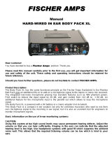
Silo pressure detector
with aluminium housing
Type plate details
CE sign with the number of the "Notified Body"
which is involved in the production control phase
Manufacturer and address
Gas and Dust marking
Ambient temperature
(Operation temperature)
Vessel pressure
(tested pressure)
EU-type examination certificate number
Type of protection
Model designation
Unique serial number
Number which the
order was handled
Month and year of delivery
W
Typ
MSD-A1F1A-B5
IBExU06ATEX1069
Auftrag-Nr. 1234567890
Industriepark RIO 103
D-74706 Osterburken
Tel. +49 62 91 64 400
M LLET
Füllstandtechnik
GmbH
0044
oben top arriba haut
-20 °C € Ta € +70 °C
p -0,08bar...+0,08bar
IP66
Contact U £ 30 V
o
I £ 0,1 A
k
C
NO
NC Connection diagram
Competence in explosion protection
M LLET
and supplement to the operating instructions
Explosion protection information
Gas+Dust and hybrid mixtures
Details of intrisically safe
supply of the signal contact.
M LLET
Füllstandtechnik
GmbH
MOLOS
MSD-A
Gas+
Dust
II 1/2D Ex ta/tb IIIC T 80 °C Da/Db
Stück Nr. 1234567890 03/21
II 2G Ex ib IIC T6 Gb
06/21 © by MOLLET MSDA-EIG-01 03
MOLLET D-74706 Osterburken Tel. +49 6291 6440-0 www.mollet.de Explosion protection information

M LLET
Füllstandtechnik
GmbH
Marking in accordance with ATEX and DIN EN IEC 60079-0
MOLOS
Silo pressure detector
MSD
Equipment category Category 1 for zone 20, 21 and 22
/ = Silo pressure detectors, which are installed
on the boundary between different zones
Category 2 for zone 21 and 22
Equivalent to valid ATEX-Product-Directive
D = Dust - Type of explosive atmosphere
Silo pressure detector for use on the boundary from zone 20 to zone 21.
Equipment group II = everything except mining
W II 1/2 D Ex ta/tb IIIC T80°C Da/Db
t = Protection by enclosure
T..°C maximum surface temperature
IIIC for flammable conductive dust, flammable non-conductive dust and flammable fibres and flyings
a = Device with „very high“ protection standard . . . . for zone 20, 21 and 22
Equipment Protection Level (EPL)
D = Dust - Type of explosive atmosphere
the Ex - symbol according to DIN EN IEC 60079-0
a = Device with “very high level of protection” for use in potentially explosive atmospheres where in
normal operation, foreseeable or infrequent faults/malfunctions no ignition hazard is given.
b = Device with „high“ protection standard . . . . . . . . for zone 21 and 22
b = Device with “high level of protection” for use in potentially explosive atmospheres where in
normal operation or foreseeable faults/malfunctions no ignition hazard is given.
W II 2G Ex ib IIC T6 Gb
Silo pressure detector for use in zone 1.
Equipment category Category 2 for zone 1 and 2
i = Protection by intrisically safe
b = Device with “high level of protection” for use in potentially explosive atmospheres where in
normal operation or foreseeable faults/malfunctions no ignition hazard is given.
Temperature class T6 = 85°C
G = Gas - Type of explosive atmosphere
G = Gas - Type of explosive atmosphere
IIC for all flammable gases
Equipment Protection Level (EPL)
b = Device with „high“ protection standard . . . . . . . . for zone 1 and 2
W II 1D Ex ta IIIC T 80 °C Da
200
Silo pressure detector for use in zone 20.
Equipment category Category 1 for zone 20, 21 and 22
Equipment category Category 1 for zone 0, 1 and 2
i = Protection by intrisically safe
a = Device with „very high“ protection standard . . . . for zone 0, 1 and 2
Silo pressure detector for use in zone 0.
W II 1G Ex ia IIC T6 Ga
04 MSDA-EIG-02 08/21 © by MOLLET
Explosion protection information MOLLET D-74706 Osterburken Tel. +49 6291 6440-0 www.mollet.de

zone 20 zone 21
M LLET
Füllstandtechnik
GmbH
T 80°C
008-0300
D p =
-0,08 bar...+0,08 bar
W
Typ
MSD-A1F1A-B5
IBExU06ATEX1069
II Ex ta/tb IIIC Da/Db 1/2D T 80 °C
Stück Nr. 1234567890 01/11
Auftrag-Nr. 1234567890
Industriepark RIO 103
D-74706 Osterburken
Tel. +49 62 91 64 400
M LLET
Füllstandtechnik
GmbH
0044
oben top arriba haut
-20 °C € Ta € +70 °C
p -0,08bar...+0,08bar
IP66
II Ex ib IIC Gb 2G T 6
Contact U £ 30 V
o
I £ 0,1 A
k
C
NO
NC
W
Typ
MSD-A2F1I-B22
IBExU06ATEX1069
II Ex ta IIIC Da 1D T 80 °C
200
Stück Nr. 1234567890 01/11
Auftrag-Nr. 1234567890
Industriepark RIO 103
D-74706 Osterburken
Tel. +49 62 91 64 400
M LLET
Füllstandtechnik
GmbH
0044
oben top arriba haut
-20 °C € Ta € +70 °C
p -0,08bar...+0,08bar
IP66
II Ex ia IIC Ga 1G T 6
Contact U £ 30 V
o
I £ 0,1 A
k
C
NO
NC
008-0301
zone 1
Ta =
-20 °C ... +70 °C
T 80°C
D p =
-0,08 bar...+0,08 bar
Ta =
The device can be installed in
the walls of vessels with
deviating atmospheric conditions
with a difference in pressure up
to Dp 80 mbar at the membran.
The device can be installed in
the walls of vessels with
deviating atmospheric
conditions with a difference in
pressure up to Dp 80 mbar at
the membran.
(the air or the bulk goods temperature) nearby the device.
maximum surface temperature T
The maximum surface temperature means the hottest point at the equipment.
The device matches with temperature class T 6.
II 2G
Order code B5
The ambient temperature Ta defines the maximum operating temperature of
Marking: II 1D / 2D
Equipment category appropriation by zones
Silo pressure detector for use in zone 1 and at the boundary from zone 20 to zone 21.
Ambient temperatures Ta
the detectors. Inside the vessel this is process temperature
Order code B22
Equipment category appropriation by zones
Silo pressure detector for use in zone 0 and zone 20.
Marking: II 1D
II 1G
maximum surface temperature T
the detectors. Inside the vessel this is process temperature
The device matches with temperature class T 6.
The ambient temperature Ta defines the maximum operating temperature of
Ambient temperatures Ta
(the air or the bulk goods temperature) nearby the device.
The maximum surface temperature means the hottest point at the equipment.
Gas+Dust and hybrid mixtures
Gas+Dust and hybrid mixtures
z
o
n
e
20
z
o
n
e
0
-20°C
...
+70°C
MOLOS
Silo pressure detector
MSD
06/21 © by MOLLET MSDA-EIG-03 05
MOLLET D-74706 Osterburken Tel. +49 6291 6440-0 www.mollet.de Explosion protection information

M LLET
Füllstandtechnik
GmbH
Special conditions and instructions for safe application
1. The installation, maintenance, initial operation, removal and repair have to be controlled resp. checked by an “authorized person” for
explosion protection.
2. For the electrical connection you have to take notice of the local and statutory requirements and/or the VDE 0100.
3. Take notice of the specifications on the data plate.
mounting or at the transport. When it is loosened, it ha s to be fitted again.
8. To secure the type of protection, the screw nut of the cable gland has to be fixed at the installation with a torsional force of min. 5.0 Nm.
12. Using the Silo pressure detector in the silo wall under deviating atmospheric conditions the maximum differential pressure has not to
exceed 80 mbar and the working temperature has not to exceed +80 °C at the membran.
4. ATTENTION! with design B22:
5. As soon as the device will be brought into the explosion hazardous area it has to be mounted immediately at the precaused place and a
cable has to be brought into the cable gland.
7. The cable gland and the plug screw were screwed and protected at the factory. Please check if they have loosened during on the
be connected in series, witch is certified for gases of explosion group IIC.
6. Using the device in ambient temperatures > +60 °C, the applied connection cables have to be made for temperatures of min. +80 °C.
If it will be fastened too strong, the IP-protection can be affected.ATTENTION!
9. The earth connection of the device has to be installed in such a way that mechanical damage will be excluded.
10. The device may put into operation with intact cap-sealing and when it is closed, only.
11. Switch off the power supply, before opening the device.
For load limitation a certified barrier or a certified isolation amplifier with an intrinsically safe circuit at least for the category “ib” has to
13. In case of existing combustible dusts with a minimum ignition energy less than 3 mJ or with a minimum ignition temperature under
For load limitation a certified barrier or a certified isolation amplifier with an intrinsically safe circuit at least for the category “ia” has to
be connected in series, witch is certified for gases of explosion group IIC.
4. ATTENTION! with design B5:
The Silo pressure detector is approved for the use in hybrid mixtures.
temperatures and follow the pertinent rules and regulations.
15. Take notice of the requirements of DIN EN 60079-14, DIN EN 60079-17 and DIN EN 1127-1, especially regarding the dust deposits and
14. In zone 0 all parts in contact with gas and dust must be made of stainless steel.
Don´t modify anything at the device or at the switching point adjusting!
18. ATTENTION safety device!
_
16. The device with an intrinsically safe electric circuit can be used in dusty explosive hazardous areas.
+300 °C (BAM assessment), the parts in contact with the dust musst be made of stainless steel.
17. Hybrid Mixtures
MOLOS
Silo pressure detector
MSD
06 MSDA-EIG-04 06/21 © by MOLLET
Explosion protection information MOLLET D-74706 Osterburken Tel. +49 6291 6440-0 www.mollet.de

L
L
E
O
T
M
-
-
F
n
ü
e
l
l
k
s
r
t
a
u
n
b
r
d
e
t
t
e
s
c
h
O
n
6
i
k
0
7
G
4
m
7
-
b
D
H
H
ExB
Wolfgang Hageleit
Geschäftsführer / Managing director
EU-Konformitätserklärung
EU-Declaration of Conformity
Wir/We MOLLET Füllstandtechnik GmbH
Industriepark RIO 103
D-74706 Osterburken
Tel. 06291 64400 Fax 06291 9846
erklären in alleiniger Verantwortung, dass das Produkt:
declares under our sole responsibility, that the product:
Silo-Druckmelder / Silo pressure detector
Typ/Type MSD-070 ... , MSD-A ...
den folgenden Europäischen Richtlinien entspricht:
conforms with the following European directives:
Niederspannungsrichtlinie Low voltage directive 2014/35/EU
Angewandte harmonisierte Normen oder normative Dokumente:
Applied harmonized standards or normative documents:
DIN EN 61010-1:2020 DIN EN 60529:2014
Und die Geräte mit W - Kennzeichnung entsprechen zusätzlich der folgenden Europäischen Richtlinie:
And the devices with W - marking conform additional with the following European directive:
ATEX-Richtlinie ATEX directive 2014/34/EU
Je nach Ausführungsvariante angewandte harmonisierte Normen oder normative Dokumente:
Depending on the design applied harmonized standards or normative documents:
DIN EN IEC 60079-0:2019 DIN EN 60079-11:2012 DIN EN 60079-26:2015
DIN EN 60079-31:2014
EU-Baumusterprüfbescheinigungsnummer:
EU-Type Examination Certificate: IBExU06ATEX1069
Ausgestellt von:.
Issued by: IBExU Institut für Sicherheitstechnik GmbH, 09599 Freiberg (0637)
Qualitätssicherung:
Quality assurance: TÜV NORD CERT GmbH, 30159 Hannover (0044)
Osterburken, den 03.06.2022
EUKE-MSD
M LLET
Füllstandtechnik
GmbH
Diese Erklärung darf nur unverändert weiterverbreitet werden.
This declaration is only allowed to hand out in unchanged form.
15_EUKE-MSD_0
Index 0
Seite/Page 1 von/of 1
/