Page is loading ...

733 Wiegand Interface Module
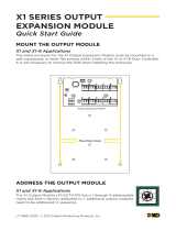
Description
The 733 Wiegand Interface Module allows you to use the powerful built-in access control capability of DMP panels
to provide system codeless entry, and arming and disarming using access control readers. Easily connect the 733
Module to the panel keypad bus.
The 733 operates on either 12 VDC or 24 VDC input and provides four supervised, programmable zones. Zones 1, 2
and 3 can be programmed for a variety of burglary or access control applications and zone 4 can be programmed as
a re zone. Additionally, the module supplies a programmable Form C Single Pole Double Throw (SPDT) Door Strike
relay, built-in piezo with remote annunciation output, data to panel LED, and a 4-position terminal for connecting
one or more external Wiegand format readers.
The Form C relay draws up to 34mA of current and its contacts are rated for 1 Amp at 24 VDC. Refer to the NC/C/NO
(Dry Contact Relay) and the Isolation Relay sections in this document for more information.
Mounting the 733 to Walls
The 733 ships installed in a decorative, high-impact plastic case that mounts directly to walls, backboards, or other
at surfaces. For easy installation, the case back and both ends have wire entrances. The bottom half of the plastic
case contains two screw holes for mounting the case on single-gang switch boxes. It is recommended that you
mount the 733 near the protected door.
Mounting the 733 in Panel Enclosures
You can also install the 733 in a panel enclosure using the standard 3-hole mounting conguration.
1. Mount the plastic standoffs to the enclosure using the three included Phillips head screws.
2. Insert the screws from the outside of the enclosure through the holes and into the plastic standoffs mounted
inside the enclosure.
3. After tightening and securing the standoffs onto the enclosure, snap the 733 onto the standoffs.
Installing the 333 Suppressor
One Model 333 Suppressor is included with the 733 Module. Refer to Figure 1 and install the suppressor across the
733 Common (C) and Normally Open (NO) or Normally Closed (NC) terminals on J2. This suppressor replaces a diode
that shipped with early 733 modules.
If the device being controlled by the relay is connected to the NO and C terminals, install the suppressor on the NO
and C terminals as well. Conversely, if the device is connected to the NC and C terminals, install the 333 Suppressor
on NC and C terminals. See Figure 1.
User Code Digits
Table 1 shows the various panel types, required operating modes for the arming/disarming feature, and the
appropriate code conguration (4 or 5 digits) for each panel. Refer to the Jumper Settings section to congure your
733 Module.
Operation XR100/XR500 Series/XR2500F XT Series XRSuper6 XR20/XR40
Arms H/A
Disarms H/A
N/A
4-digit
4-digit
4-digit
4-digit
4-digit
4-digit
4-digit
Arms A/P
Disarms A/P
N/A
4-digit
N/A
4-digit
N/A
4-digit
N/A
4-digit
Arms Area(s)
Disarms Area(s)
N/A
4 or 5 digits
N/A
4-digit*
—
—
N/A
4-digit*
*During entry delay only
—Not available on this panel type
N/A Requires additional selection to arm
Table 1: Panel Operating Modes and Code Conguration
InstallatIon sheet

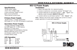
Jumper Settings
Figure 1 shows the J4 location. If you are using 4-digit codes, place the 4/5 digit jumper (J4) across the two left
pins. If you are using 5-digit codes, place the 4/5 digit jumper (J4) across the two right pins. Refer to the User
Code Digits section to determine the setting for your installation.
Figure 1: 733 Wiring Diagram
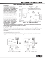
Set the 733 Module Address
The 733 is a supervised module and cannot operate in unsupervised mode.
The following panels automatically recognize the 733 switch settings:
• XRSuper6 and XR20 panels use addresses 1 to 4
• XR40 uses addresses 1 to 8
• XT Series panels uses addresses 1 to 5.
For XR100 Series, select any address from 1 to 8 in panel programming Device Setup. For XR500 Series and XR2500F
operation, select any address from 1 to 16 in panel programming Device Setup. To change the current address, refer
to Figure 2 and move the slide switches to the appropriate address positions.
ON
1 2 3 4
ON
1 2 3 4
ON
1 2 3 4
ON
1 2 3 4
ON
1 2 3 4
ON
1 2 3 4
ON
1 2 3 4
ON
1 2 3 4
ON
1 2 3 4
ON
1 2 3 4
ON
1 2 3 4
ON
1 2 3 4
ON
1 2 3 4
ON
1 2 3 4
ON
1 2 3 4
ON
1 2 3 4
1 2 3 4
5 6 7 8
9 10 11 12
13 14 15 16
Figure 2: 733 Addresses
AS NC C NO
Z1 Z2 Z3 Z4+ Z4– RA
GNDGND
J2
1234
RED WHT GRN BLK
J3
1234
REDYEL GRN BLK
J1
S1
ON
PANEL
WIEGAND
LEV
SERIAL NO.
TXD
CR1
U1
U2
U3
J4
4 5
PC-0043
R02
MODEL
733
DS1
Card Reader
4-5 Digit
J4 Jumper Header
J3 Terminal
To Wiegand Reader
Red
White (Data 1)
Black
Green (Data 0)
Note: Only use shielded wire if specified by the
reader manufacturer. The shield must only be
connected to the reader. Refer to reader installation
documentation for more information. Maximum line
impedance is 4 Ohms.
J1 Terminal
To Panel
To Power Supply
negative terminal
To Keypad
Data Bus
Keypad Data Bus
Red
Yellow
Black
Green
Model 333 Suppressor
Wire the Suppressor to the Common and Normally Open or Normally
Closed depending upon which terminals are used for the device.
Zone 1
Zone 2
Zone 3
Zone 4
Normally Open
Normally Closed
Common
Remote Audible Annunciator
Armed Status Output
733 Module
J2 Terminal
Shield
Note: Use 1K Ohm EOL for each zone.
J5
All zones are power limited and supervised
Maximum zone line impedance is 100 Ohms
Zone 4 Ground fault detected at 1020 Ohms or less
CAUTION: DO NOT USE
LOOPED WIRE UNDER
TERMINALS. BREAK WIRE
RUN TO PROVIDE
SUPERVISION OF
s
s
s
s
ssss
ss s s
Digital Monitoring Products 733 Installation and Programming Guide
2

733 Module Wiring
The 733 connects to the keypad bus and a Wiegand format reader. Refer to this guide for proper wiring.
Panel terminal block
Connect the supervised 4-wire keypad bus to the Panel terminals marked Red, Yellow, Green, and Black as shown in
Figure 1. If you are continuing the wire run to another 733 Module or to a keypad, connect both wires of the same
color under the same terminal as shown in Figure 1.
Wiegand terminal block
Figure 1 shows a reader with wires colors Red, White, Green, and Black. The wire colors may be different for the
reader being installed. Connect the reader wires to J3 terminals 1, 2, 3, and 4. As shown in Figure 1, the Green
wire provides D0, or Data Zero, and the White wire provides D1, or Data One. The Red wire provides 12 VDC output
and the Black wire is ground. Refer to the literature provided with the reader for wire coding, wire distance, cable
type (such as shielded), and other specications. If you are powering the readers from an auxiliary power source,
refer to 12 VDC Access Control Readers later in this document.
Zone terminals
Terminal Zone 1 and Zone 2 are burglary protection zones. Zone 3 is for Request to Exit features discussed in the
Zone 3 Request to Exit section. Use the GND terminals as common terminals for the zones. Zone 4 terminal
provides a non-powered Class B, Style A ungrounded zone suitable for connection to re devices such as 4-wire
smoke detectors and heat detectors. Use the supplied DMP Model 311 1k Ohm End-of-Line resistors on each zone.
AS (Armed Status)
The AS terminal provides a common unsupervised switched ground for a visual or audible armed status indicator that
turns on when the area Armed Status is sent to the 733 such as SYSTEM ON or ALL SYSTEM ON. Connect the negative
side of an Armed Status output to J2 terminal AS. The AS terminal may stay grounded up to 20 seconds after the
system disarms. Power Limited, maximum current 50mA.
RA (Remote Annunciation)
The RA terminal provides a common unsupervised switched ground for a remote annunciator (RA) that turns on when
the 733 on-board piezo turns on. Connect the negative side of a remote annunciator to J2 terminal RA. The remote
annunciator activates when the RA switches to ground. The remote annunciator silences when the RA restores.
Power Limited, maximum current 50mA @ 30 VDC.
NC/C/NO (Dry Contact Relay)
The 733 also provides an internal Form C SPDT relay for controlling door strikes or magnetic locks. The three relay
terminals on J2 marked NC C NO allow you to connect the device wiring to the relay for control by the module. See
Figures 4 and 5 for proper door strikes and magnetic locks wiring.
Note: The Form C relay draws up to 35mA of current. The contacts are rated for 1 Amp resistive at 24 VDC. When
connecting multiple locks to the Form C relay, the total current for all locks cannot exceed 1 Amp. If the total
current for all locks exceeds 1 Amp, problems may arise and the relay may become latched. Install an isolation relay
to allow multiple locks. For information on wiring isolation relays, see the Isolation Relay section of this guide.
Wiring Specications for Keypad Bus
1. DMP recommends using 18 or 22-gauge unshielded wire for all keypad and LX-Bus circuits. Do not use
twisted pair or shielded wire for LX-Bus and keypad bus data circuits. All 22-gauge wire must be connected
to a power-limited circuit and jacket wrapped.
2. On keypad bus circuits, to maintain auxiliary power integrity when using 22-gauge wire do not exceed 500
feet. When using 18-gauge wire do not exceed 1,000 feet. To increase the wire length or to add devices,
install an additional power supply that is listed for Fire Protective Signaling, power limited, and regulated
(12 VDC nominal) with battery backup.
Note: Each panel allows a specic number of supervised keypads. Add additional keypads in the
unsupervised mode. Refer to the panel installation guide for the specic number of supervised keypads
allowed.
3. Maximum distance for any one bus circuit (length of wire) is 2,500 feet regardless of the wire gauge. This
distance can be in the form of one long wire run or multiple branches with all wiring totaling no more than
2,500 feet. As wire distance from the panel increases, DC voltage on the wire decreases. Maximum number
of LX-Bus devices per 2,500 feet circuit is 40.
4. Maximum voltage drop between the panel (or auxiliary power supply) and any device is 2.0 VDC. If the
voltage at any device is less than the required level, add an auxiliary power supply to the circuit. When
voltage is too low, the devices cannot operate properly.
For additional information refer to the panel's Installation Guide, the 710/710F Installation Sheet (LT-0310), and/or
the LX-Bus/Keypad Bus Wiring Application Note (LT-2031).
733 Installation and Programming Guide Digital Monitoring Products
3

Enrolling Users
DMP 693, 793, 7063, 7063A, 7073, 7073A, 7163 and 7173 LCD keypads can be used to enroll users. You may also use
Remote Link™ or System Link™ with an Admin Reader to quickly enroll users in the system. The 733 cannot be used
to enroll users.
Access Control Feature
The 733 Module allows users to present an access credential, such as a card or keyfob, to an access control reader.
The reader then sends the user code information to the 733 Module that reads the user code and veries its
authority with the panel. After verifying the code has the proper authority, the 733 Module powers its on-board
Form C relay releasing a door strike or magnetic lock.
Door contact zone with Soft-Shunt™
If the door being released by the 733 Module is protected (contacted), provide a 40-second Soft-Shunt™ entry/exit
timer by connecting the contact wiring to Zone 2 on the 733 Module. Once the on-board Form C relay activates, the
user has ve seconds to open the door connected to Zone 2. The zone is then shunted for 40 seconds.
After 30 seconds elapse, the 733 Module sounds its built-in piezo alerting the user the Soft-Shunt™ timer is about to
expire. If the door is still open at the end of the 40-second timer a zone fault is sent to the panel for Zone 2.
5 Second
Strike
40-Second "Soft-Shunt"
and entry/exit timer.
10 seconds before
the shunt time expires,
the device beeps if
the door is still open.
End of
timer.
40
Seconds
A zone open/short is
indicated if the door
remains open.
Figure 3: Soft-Shunt™ Timeline
Zone 3 Request to Exit
Also connect a PIR, other motion sensing device, or a mechanical switch to Zone 3 on the module to provide
Request-to-Exit (REX) capability to the system. When Zone 3 is shorted, the on-board Form C relay activates for
5 seconds. During this time, the user can open the protected door to start the 40-second Soft-Shunt™ entry/exit
timer. After ve seconds, the relay restores the door to its locked state.
The 733 Module with rmware version 103 (4/25/01) and higher provides a shunt-only option for REX on Zone 3.
When Zone 3 is opened from a normal state, only a Soft-Shunt occurs: the on-board relay is not activated.
This shunt-only option uses two methods of Request-to-Exit. The rst REX device provides the 40-second Soft-Shunt
entry/exit timer. The second REX device, or manual device such as a door knob, unlocks the door.
As an example of the shunt-only conguration, a door to an ofce is locked 24 hours a day. Users pass a REX motion
detector positioned by the door to begin the 40-second exit timer. Within 5 seconds the user must then manually
activate a second device, such as a REX device or manual door knob, to unlock the door. If the door is opened after
5 seconds, the zone goes into alarm.
After 30 seconds elapse, the 733 Module begins sounding its built-in piezo alerting the user that the Soft-Shunt is
about to expire. If the door is still open at the end of the 40-second Soft-Shunt timer a zone fault is sent to the
panel for Zone 2.
12/24 VDC Access Control Readers
Power the 733 Module from either a 12 VDC or 24 VDC input voltage without any board changes. The 12 VDC power
can be provided by the Command Processor™ panel or from a separate listed burglary and re alarm auxiliary power
supply. All 24 VDC power must be provided by a separate auxiliary power supply or the auxiliary output of a 24 VDC
panel. Do not ground the power supply to the 733 or Command Processor™ panel.
Direct Voltage Output to Reader
If you are powering the 733 from 12 VDC power, the voltage output for the Wiegand reader is also 12 VDC, 200mA
power limited. If you are powering the 733 from 24 VDC power, the voltage output for the Wiegand reader is also 24
VDC. Do not ground the power supply to the 733 or Command Processor™ panel.
The 733 contains an on-board current limiting device that protects the power input to the 733 from shorts on
external wiring.
Digital Monitoring Products 733 Installation and Programming Guide
4

Magnetic Lock and Door Strike Wiring
Control door switches and magnetic locks by using the Form C relay on the 733 Module. Use an additional power
supply to power door strikes and magnetic locks. Refer to Figures 4 and 5 for wiring information.
J3
J2
J1
PANELWIEGAND
Z1 GNDZ2Z3GND Z4+Z4- AS RA NC CNO
REDYEL GRNBLK REDWHT GRNBLK
Card Reader
Common Normally Open
-+
DC Door Strike
DMP 502 or
505 Power
Supply
Suppressor
To Keypad Bus
Figure 4: Door Strike Wiring Figure 5: Magnetic Lock Wiring
Isolation Relay
The 1 Amp programmable Form C Relay can control a device that draws less than 1 Amp current. If a device draws
more than 1 Amp of current, or the sum of all devices controlled by the Form C Relay exceeds 1 Amp, an isolation
relay or a 734 Module must be used. Refer to Figures 6 and 7 for isolation relay wiring.
J3
J2
J1
PANELWIEGAND
Z1 GNDZ2Z3GND Z4+Z4- AS RA NCCNO
REDYEL GRNBLK REDWHT GRNBLK
Card Reader
Common Normally Open
Magnetic
Lock
DMP 502 or
505 Power
Supply
Suppressor
733
External
Relay
NC
C
NO
To Keypad Bus
Figure 6: Isolation Relay and Magnetic Lock
J3
J2
J1
PANELWIEGAND
Z1 GNDZ2Z3GND Z4+Z4- AS RA NC CNO
REDYEL GRNBLK REDWHT GRNBLK
Card Reader
Common Normally Open
DC Door
Strike
DMP 502 or
505 Power
Supply
Suppressor
733
External
Relay
NC
C
NO
To Keypad Bus
Figure 7: Isolation Relay and Door Lock
J3
J2
J1
PANELWIEGAND
Z1 GNDZ2Z3GND Z4+Z4- AS RA NCCNO
REDYEL GRNBLK REDWHT GRNBLK
Card Reader
Common
Normally Closed
-+
Magnetic Door Lock
DMP 502 or
505 Power
Supply
Suppressor
To Keypad Bus
733 Installation and Programming Guide Digital Monitoring Products
5

LT-0343 1.02 © 2008 Digital Monitoring Products Inc.
8445
Compliance Listing Specications
UL Commercial Fire
The Model 733 Interface Module must be used in conjunction with at least one listed DMP keypad.
Any Auxiliary Power Supplies must be regulated, power limited, and listed for Fire Protective Signaling Service.
UL Access Control
For Access Control applications, conguring as fail-safe or fail-secure shall be determined by the local Authority
Having Jurisdiction (AHJ). This system is not intended to be used in place of listed panic hardware.
Accessories
Proximity Readers
PP-6005B ProxPoint® Plus
MP-5365 MiniProx™
PR-5455 ProxPro® II
MX-5375 MaxiProx®
TL-5395 ThinLine II®
Proximity Credentials
1306 DMP Prox Patch
1306PW Prox Patch™
1326 ProxCard II® Card
1346 ProxKey II® Access Device
1351 ProxPass®
1386 ISOProx II® Card
Specications
Primary Power 8.5 VDC to 28.5 VDC
Current Draw
Standby 30mA
+ 1.6mA per active zone
Alarm 30mA
+ 20mA with Annunciator ON
+ 2mA per active zone
Zone Voltage
5 VDC, max 2mA
Dimensions 4.5” W x 2.75” H x 1.75” D
Compatibility
XT Series, XRSuper6/XR20/XR40, XR100, XR500
Series, or XR2500F panels
Listings and Approvals
FCC Part 15
California State Fire Marshall (CSFM)
New York City (FDNY COA #6055)
Underwriters Laboratory (UL) Listed
Commercial Burglar and Fire Accessory Zone Expander
Signaling Device with Access Control
ANSI/UL 294 Access Control System Units
ANSI/UL 1610 Central Station Burglar
ANSI/UL 985 Household Fire-warning
ANSI/UL 864 Fire-protective Signalling
ANSI/UL 1023 Household Burglar
ANSI/UL 609 Local Burglar
ANSI/UL 365 Police Connected Burglar
ANSI/UL 1076 Proprietary Burglar
800-641-4282
www.dmp.com
Made in the USA
INTRUSION • FIRE • ACCESS • NETWORKS
2500 North Partnership Boulevard
Springfield, Missouri 65803-8877
/