Page is loading ...

R
www.quadrafi re.com 7014-188C November 22, 2011
CB1200-I PELLET INSERT
Owner’s Manual
Installation and Operation
CB1200MI-MBK
Model:
DO NOT DISCARD THIS MANUAL
NOTICE
• Important operating and
maintenance instruc-
tions included.
• Leave this manual with
party responsible for use
and operation.
• Read, understand and
follow these instruc-
tions for safe installa-
tion and operation.
DO NOT
DISCARD
WARNING
Please read this entire manual
before installation and use of this
pellet fuel-burning room heater.
Failure to follow these instructions
could result in property damage,
bodily injury or even death.
• Do not store or use gasoline or other fl am-
mable vapors and liquids in the vicinity of this
or any other appliance.
• Do not overfi re - If any external part starts to
glow, you are overfi ring. Reduce feed rate.
Overfi ring will void your warranty.
• Comply with all minimum clearances to com-
bustibles as specifi ed. Failure to comply may
cause house fi re.
Check building codes prior to installation.
• Installation MUST comply with local, regional, state and national
codes and regulations.
• Consult local building, fi re offi cials or authorities having jurisdic-
tion about restrictions, installation inspection, and permits.
CAUTION
Tested and approved for wood pellets and shelled
fi eld corn fuel only. Burning of any other type of fuel
voids your warranty.
CAUTION
O- T L
Tested and
Listed by
Portland
Oregon USA
OMNI-Test Laboratories, Inc.
CUS
WARNING
Hot glass will cause burns.
• Do not touch glass until it is cooled
• NEVER allow children to touch glass
• Keep children away
• CAREFULLY SUPERVISE children in same room as
fi replace.
• Alert children and adults to hazards of high
temperatures.
High temperatures may ignite clothing or other
fl ammable materials.
• Keep clothing, furniture, draperies and other fl ammable
materials away.
HOT SURFACES!
Glass and other surfaces are
hot during operation AND
cool down.

Page 2 7014-188C November 22, 2011
R
CB1200-I Pellet Insert
and Welcome to the Quadra-Fire Family!
Hearth & Home Technologies welcomes you to our tradition
of excellence! In choosing a Quadra-Fire appliance, you
have our assurance of commitment to quality, durability, and
performance.
This commitment begins with our research of the market,
including ‘Voice of the Customer’ contacts, ensuring we
make products that will satisfy your needs. Our Research
and Development facility then employs the world’s most
advanced technology to achieve the optimum operation of
our stoves, inserts and fi replaces. And yet we are old-fash-
ioned when it comes to craftsmanship. Each unit is meticu-
lously fabricated and surfaces are hand-fi nished for lasting
beauty and enjoyment. Our pledge to quality is completed
as each model undergoes a quality control inspection.
From design, to fabrication, to shipping:
We wish you and your family many years of enjoyment in
the warmth and comfort of your hearth appliance. Thank
you for choosing Quadra-Fire.
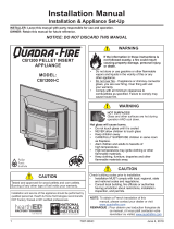
CLEARANCE TO COMBUSTIBLES LABEL LOCATED INSIDE HOPPER LID
SERIAL NUMBER & MANUFACTURE DATE LABEL LOCATED UNDER TOP ON INSIDE OF HOPPER BODY
NOTE: Consult insurance carrier, local building inspector, fi re
offi cials or authorities having jurisdiction over restrictions,
installation inspection and permits.
Safety and clearance section located on inside of hopper lid./
Serial Number section located under top on inside of hopper body.
La section se réfé dux distances et mescres de sécurité est située à l'intérieut du couvércle de la tré la bôitre à feu.
La section du numéro de série est située en dessous du couvercle à l'intérieur de la trémie.
Listed Solid Fuel Room Heater/Pellet Type Insert. Also suitable for
Mobile Home Installation. This appliance has been tested and listed for
use in Manufactured Homes in accordance with OAR 814-23-9000
through 814-23-909.
R
1200-I Pellet Insert 1445 Highway North, Colville, WA 99114
www.quadrafire.com
Install and use only in accordance with manufacturer's installation and
operating instructions. Contact local building or fire officials about
restrictions and inspection in your area.
WARNING - FOR MOBILE HOMES: Do not install appliance in a sleeping
room. An outside combustion air inlet must be provided. The structural
integrity of the mobile home floor, ceiling and walls must be maintained.
Refer to manufacturer's instructions and local codes for precautions required
for passing chimney through a combustible wall or ceiling. Inspect and clean
vent system frequently in accordance with manufacturer's instructions.
DO NOT CONNECT THIS UNIT TO A CHIMNEY SERVING ANOTHER APPLIANCE.
Use a 3" or 4" diameter type "L" or "PL" venting system.
Tested to: ASTM E1509-95, UL127, ULC S628-93, ULC S610-M87,
ULC/ORD C1482-M1990 Room Heating Pellet Burning Type, (UM) 84-HUD
FOR USE
ONLY WITH PELLETIZED WOOD OR SHELLED FIELD CORN FUEL.
Input Rating Maximum 5.5 lb fuel/hr.
Electrical Rating:
115 VAC, 60 Hz, Start 4.1 Amps, Run 1.1 AMPS.
Route power cord away from unit. Do not route cord under or in front of
appliance.
DANGER:
Risk of electrical shock. Disconnect power supply before
servicing. Replace glass only with 5mm ceramic available from your dealer.
To start, set thermostat above room temperature, the stove will light
automatically. To shutdown, set thermostat to below room temperature. For
further instruction refer to owner's manual.
Keep viewing and ash removal doors
tightly closed during operation.
MINIMUM CLEARANCES TO COMBUSTIBLE MATERIALS
Masonry or *Zero Clearance Minimum Clearances to Combustible
Maçonnene ou zéro distance foyer distances minimales à tout matériel combustible.
AS A BUILT-IN UNIT WITH REAR SHROUD
7014-080D
U.S. ENVIRONMENTAL PROTECTION AGENCY OMNI Test Laboratories, Inc., Portland, Or Report/Rapport 061-S-13-2
This model is exempt from EPA certification under 40 CFR 60.531 by definition [Wood Heater (A) "Air-to-Fuel Ratio"].
2010 2011 2012 JAN FEB MAR APR MAY JUNE JULY AUG SEPT OCT NOV DEC
7014-080D
1200-I PELLET INSERT
A Louvers to combustible wall
B Insert top to mantel
C Front Facing
D* Hearth Extension - Front
E* Hearth Extension - Side
6” (152mm)
12” (305mm)
3” (76mm)
6" (152mm)
8” (203mm)
DO NOT REMOVE THIS LABEL / NE PAS ENLEVER L'ÉTIQUETTE
SERIAL NO.
/
NUMÉRO DE SÉRIE
Report / Rapport
#061-S-13-2
DO NOT REMOVE THIS LABEL / NE PAS ENLEVER L'ÉTIQUETTE
Manufactured by:
Fabriqué par:
0" (Omm) Clearance To Exposed Section and Face Trim
PRÉVENTION DES FEUX DE MAISON
I
nstallez et utilisez en accord avec les instructions d'installation et d'opération du
fabricant. Contactez le bureau de la construction ou le bureau des incendies au
sujet des restrictions et des inspections d'installation dans votre voisinage. Ne pas
obstruez l'espace en dessous de l'appareil.
AVIS - Pour Les Maisons Mobiles: Ne pas installer dans une chambre à
coucher. Un tuyau extérieur de combustion d'air doit être installé et ne doit pas
être obstrué lorsque l'appareil est en usage. La structure intégrale du plancher, du
plafond et des murs de la maison mobile doit être maintenue intacte.
Référez vous aux instructions du fabricant et des codes locaux pour les
précautions requises pour passer une cheminée à travers un mur ou un plafond
combustibles, et les compensations maximums.
Inspectez et nettoyez la cheminée fréquemment. Ne pas connecter cet appareil
à une cheminée servant un autre appareil.
Utilisez systèm de ventilation "L" ou "P" diamètre 76mm ou 102mm.
Testé à: ASTM E1509-95, UL127, ULC S628-93, ULC S610-M87, ULC/ORD
C1482-M1990 Room Heating Pellet Burning Type, APFI, (UM) 84-HUD POUR
USAGE AVEC LES BOULETTES DE BOIS OU DE COMBUSTIBLE DE MAIS
ÉCOSSÉ DES CHAMPS.
Consommahon maximale à l'entrée (sans pertes) 2.5 kg/h.
Puissance Électrique: 115 VAC, 60 Hz, Début 4.1 Amps, Courir 1.1 Amps,
Éloignez le fil électrique de l'appareil. Ne pas faire passer le fil électrique au
dessus ou en dessous de l'appareil.
DANGER: Il y a risque de décharge électrique. Déconnectez le fil électrique de la
prise de contact avant le service.
Remplacez la vitre seulement avec une vitre céramique de 5 mm disponible chez
votre fournisseur.
Pour allumer, monter la température du thermostat au dessus de la température de la
pièce, le poêle s'allumera automatiquement. Pour éteindre, descendre la
température du thermostat en dessous de la température de la pièce. Pour des
instructions supplémentaires, référez vous au manuel du propriétaire. Gardez la
porte d'ouverture et la porte des cendres fermées hermétiquement durant l'opération.
Appareil de chauffage inséré de combustible solide/de type de boulettes. Accepté dans l'installation
dans les maisons mobiles. Cet appareil a été testé et enregistré pour l
'usage dans les Maisons
Mobiles en accord avec OAR 814-23-9000 jusqu'à 814-23-909.
B
D
C
E
B
C
A
*Zero clearance installation requires
non-combustible hearth material with an R
value of 3.0 or more (“k” value of .58) or a
1” (25mm) air space between insert base
and hearth. Floor Protection Part
811-0730 is available from your dealer for
the section under the insert body only.
HEARTH PROTECTION
*See hearth protection note above
A Lucarne au mur combustible
B Dessus de l'insert à la tablette de cheminée
C Revêtement facial
D* Protechion de sol - frontal
E* Protechon ole sol - côté
*Voir les notes sur la protechion ole sol ci-dessus.
152mm
305mm
76mm
152mm
203mm
A Top of Inside Shroud
B
Sides of Inside Shroud
C Back of Inside Shroud)
D Vent Pipe to Combustible
E From Panel Edge
0" (0mm)
3" (76mm)
0" (0mm)
0" (0mm)
2-1/2"
(64mm)
3" (76mm)
0" (0mm)
Rear Vent
Top Vent
Top or Rear
Rear Vent
Top Vent
)
Rear Vent
QUADRA-FIRE
PREVENT HOUSE FIRES
SIDE WALL
A
B
C
D
E
CAUTION:
HOT WHILE IN OPERATION DO NOT TOUCH. KEEP CHILDREN, CLOTHING AND FURNITURE
AWAY. CONTACT MAY CAUSE SKIN BURNS. SEE NAMEPLATE AND INSTRUCTIONS. Operate this unit
with fuel hopper lid closed. Failure to do so may result in emissions products' combustion from the hopper
under certain conditions. Maintain hopper seal in good condition. Do no over fill the hopper.
ATTENTION:
CHAUD LORS DE L'OPÉRATION. NE PAS TOUCHER. GARDEZ LES ENFANTS ET LES VÊTEMENTS LOIN DE
L'ESPACE DÉSIGNÉ DE L'INSTALLATION. LE CONTACT PEUT CAUSER DES BRÛLURES À LA PEAU. VOIR L'ÉTIQUETTE ET LES
INSTRUCTIONS. Opérez cet appareil avec le couvercle de la trémie fermé. Le défaut de ne pas suivre les instructions peut résulter,
sous certaines conditions, en une combustion des émissions des produits venant de la trémie. Ne pas remplir la trémie trop pleine.
MANTEL
007C
MADE IN CHINA / FAIT AUX CHINE
O-T L
Tested and
Listed by
Portland
Oregon USA
OMNI-Test Laboratories, Inc.
CUS

R
November 22, 2011 7014-188C Page 3
CB1200-I Pellet Insert
Section 1: Listing and Code Approvals
A. Appliance Certifi cations ......................4
B. Mobile Home Approved ......................4
C. Glass Specifi cations ............................4
D. Electrical Rating ..................................4
E. BTU & Effi ciency Specifi cations ..........4
Section 2: Getting Started
A. Design, Installation & Location
Considerations ....................................5
B. Locating Your Appliance & Chimney ..6
C. Thermostat Location ...........................6
D. Draft ....................................................6
E. Negative Pressure ..............................6
B. Fire Safety ..........................................7
C. Tools & Supplies Needed ...................7
D. Inspect Appliance, Components
and Pre-Check List .............................7
Section 3: Dimensions & Clearances
A. Appliance Dimensions ........................8
B. Clearances to Combustibles
As A Built-In, UL and ULC ..................9
C. Clearances to Combustibles,
Masonry & Zero Clearance .................10
D. Minimum Opening for Factory
Built Fireplace .....................................10
E. Masonry Minimum Opening ................10
F. Floor Protection ..................................10
G. Calculating Alternate Floor
Protection Material ..............................11
H. Prefabricated Metal Chimney .............11
I. Removing Floor of Factory Built
Fireplace .............................................12
J. Altering Factory-Built Fireplace ...........12
Section 4: Vent Information
A. Chimney & Exhaust Connections ........13
B. Venting Termination Requirements ....13
C. Equivalent Feet of Pipe.......................14
D. Pipe Selection Chart ...........................14
Section 5: Venting Systems
A. Full Reline with Outside Air-Horizontal 15
B. Full Reline with Outside Air-Vertical ....16
Section 6: Mobile Home ..................................17
Section 7: Appliance Set-Up
A. Rear Shroud Installation .....................18-19
B. Outside Air Kit .....................................20
C. Adjustable Hopper Option...................20
D. Grille Installation .................................20
E. Adjustable Hearth Support..................21
F. Panel & Trim .......................................22-23
G. Brick Set Installation ...........................24
H. Brick Clip Installation ...........................24
I. Log Set Placement ..............................25
J. Thermostat Installation ........................25
Section 8: Operating Instructions
A. Fuel Size, Material & Storage .............26
B. General Operation Information ...........27
C. Before Your First Fire .........................27
D. Starting Your First Fire ........................27
E. Fire Characteristics .............................28
F. Feed Rate Adjustment .......................28
G. Ignition Cycles ....................................28
H. Frequently Asked Questions...............29
Section 9: Troubleshooting ............................31-32
Section 10: Maintaining & Servicing Appliance
A. Proper Shutdown Procedure ...............33
B. Quick Reference Maintanence Chart ..33
C. General Maintenance & Cleaning .......33-36
D. High Ash Content Maintenance ..........37
E. Glass Replacement .............................38
F. Igniter Replacement ............................39
G. Baffl e Removal ....................................39
Section 12: Reference Material
A. Component Functions.........................40-41
B. Component Locations .........................42
C. Exploded Drawings .............................43
D. Service Parts & Accessories...............44-48
E. Service & Maintenance Log ................49
E. Warranty Policy ...................................50-51
F. Contact Information ............................52
TABLE OF CONTENTS
Safety Alert Key:
• DANGER! Indicates a hazardous situation which, if not avoided will result in death or serious injury.
• WARNING! Indicates a hazardous situation which, if not avoided could result in death or serious injury.
• CAUTION! Indicates a hazardous situation which, if not avoided, could result in minor or moderate injury.
• NOTICE: Indicates practices which may cause damage to the fi replace or to property.

Page 4 7014-188C November 22, 2011
R
CB1200-I Pellet Insert
1Listing and Code Approvals
A. Appliance Certifi cation
C. Glass Specifi cations
E. BTU & Effi ciency Specifi cations
This appliance is equipped with 5mm ceramic glass. Replace
glass only with 5mm ceramic glass. Please contact your
dealer for replacement glass.
This appliance is approved for mobile home installations
when not installed in a sleeping room and when an outside
combustion air inlet is provided. The structural integrity of the
mobile home fl oor, ceiling, and walls must be maintained.
The appliance must be properly grounded to the frame of
the mobile home and use only listed pellet vent, Class “L”
or “PL” connector pipe. A Quadra-Fire Outside Air Kit must
be installed in a mobile home installation.
Note: This appliance is also approved for installation
into a shop.
B. Mobile Home Approved
NOTE: This installation must conform with local codes. In
the absence of local codes you must comply with the ASTM
E1509-95, ULC S628-93, ULC S610-M87, ULC/ORD-C-
1482-M1990, (UM) 84-HUD.
D. Electrical Rating
115 VAC, 60 Hz, Start 4.1 Amps, Run 1.1 Amps
*BTU output will vary, depending on the brand of fuel you
use in your appliance. Consult your Quadra-Fire dealer
for best results.
MODEL: 1200-I Pellet Insert
LABORATORY: OMNI Test Laboratories, Inc
REPORT NO. 061-S-13-2
TYPE: Solid Fuel Room Heater/Pellet Fuel
Burning Type Insert
STANDARD: ASTM E1509-95, ULC S628-93, ULC
S610-M87, ULC S628-M93 and ULC/
ORD-C1482-M1990 Room Heater Pellet
Fuel Burning Type and (UM) 84-HUD,
Mobile Home Approved
Emissions Rating: .9 grams/hr
*BTU Output: 14,000 - 40,000 / hr
Heating Capacity: up to 2,500 sq. ft. depending
on climate zone
Hopper Capacity: 38-45 lbs
Fuel: Wood Pellets or Shelled Corn
Shipping Weight: 243 lbs
NOTE: Hearth & Home Technologies, manufacturer of
this appliance, reserves the right to alter its products,
their specifi cations and/or price without notice.
WARNING! Risk of Fire! Hearth & Home Technologies dis-
claims any responsibility for, and the warranty and agency
listing will be voided by the above actions.
DO NOT:
• Install or operate damaged appliance
• Modify appliance
• Install other than as instructed by Hearth & Home
Technologies
• Operate the appliance without fully assembling all
components
• Overfi re
• Install any component not approved by Hearth &
Home Technologies
• Install parts or components not Listed or approved.
Improper installation, adjustment, alteration, service or
maintenance can cause injury or property damage.
For assistance or additional information, consult a qualifi ed
installer, service agency or your dealer.
Quadra-Fire is a registered trademark
of Hearth & Home Technologies.
NOTE: Some generator or battery back-up systems
may not be compatable with the micro-processor elec-
tronics on this appliance. Please consult the power
supply manufacturer for compatable systems.

R
November 22, 2011 7014-188C Page 5
CB1200-I Pellet Insert
2Getting Started
A
.
Design, Installation & Location Consider-
ations
Warning! Risk of Fire Damaged parts could impair safe
operation. Do NOT install damaged, incomplete or substitute
components.
1. Appliance Location
NOTICE: Check building codes prior to installation.
• Installation MUST comply with local, regional, state and
national codes and regulations.
• Consult insurance carrier, local building inspector, fi re
offi cials or authorities having jurisdiction over restrictions,
installation inspection and permits.
It is a good idea to plan your installation on paper, using
exact measurements for clearances and fl oor protection,
before actually beginning the installation
Consideration must be given to:
• Safety, convenience, traffi c fl ow
• Placement of the chimney and chimney connector.
• If you are not using an existing chimney, place the appli-
ance where there will be a clear passage for a factory-
built listed chimney through the ceiling and roof.
• Installing an optional outside air kit would affect the loca-
tion of the vent termination.
CAUTION! If burning shelled fi eld corn, you must use ap-
proved venting specifi cally designed for corn to prevent corro-
sion or degradation. Follow the instructions from the venting
manufacturer.
Since pellet exhaust can contain ash, soot or sparks, you
must consider the location of:
• Windows
• Air Intakes
• Air Conditioner
• Overhang, soffi ts, porch roofs, adjacent walls
• Landscaping, vegetation
When locating vent and venting termination, vent above roof
line when possible.
Marginal Location:
• Below peak
Location NOT recommended:
• Not the highest point of the roof
• Wind loading possible
Multi-level Roofs
Windward
Leeward
Recommended:
Outside Air Intake
on windward side
NOT recommended:
Outside Air Intake
on leeward side
Recommended Location:
• Above peak
Recommended:
• Insulated exterior chase
in cooler climates
Recommended Location:
• Above peak
• Inside heated space
Location NOT recommended:
• Too close to tree
• Below adjacent structure
• Lower roof line
• Avoid outside wall
Marginal Location:
• Wind loading possible
NOTICE: Locating the appliance in a location of
considerable air movement can cause intermittent smoke
spillage from appliance. Do not locate appliance near:
• Frequently open doors
• Central heat outlets or returns
Figure 5.1

Page 6 7014-188C November 22, 2011
R
CB1200-I Pellet Insert
C. Thermostat Location
The thermostat’s location will have some effect on the
appliance’s operation. When the thermostat is located close
to the appliance, it may require a slightly higher temperature
setting to keep the rest of the house comfortable. If the
thermostat location is in an adjacent room or on a different
fl oor level, you will notice higher temperatures near the
appliance.
CAUTION
• DO NOT CONNECT THIS UNIT TO A CHIMNEY FLUE
SERVICING ANOTHER APPLIANCE.
• DO NOT CONNECT TO ANY AIR DISTRIBUTON DUCT
OR SYSTEM.
Fire Hazard.
WARNING
• Do not operate appliance before reading
and understanding operating instructions.
• Failure to operate appliance properly may
cause a house fi re.
Location of the appliance and chimney will affect
performance.
• Install through the warm airspace enclosed by the building
envelope. This helps to produce more draft, especially
during lighting and die-down of the fi re.
• Penetrate the highest part of the roof. This minimizes the
effects of wind loading.
• Locate termination cap away from trees, adjacent
structures, uneven roof lines and other obstructions.
• Minimize the use of chimney offsets.
• Consider the appliance location relative to fl oor and ceiling
and attic joists.
• Take into consideration the termination requirements on
Page 11.
B. Locating Your Appliance & Chimney
D. Draft
Draft is the pressure difference needed to vent appliances
successfully. When an appliance is drafting successfully, all
combustion byproducts are exiting the home through the
chimney.
Considerations for successful draft include:
• Preventing negative pressure
• Location of appliance and chimney
NOTICE: Hearth & Home Technologies assumes no
responsibility for the improper performance of the chimney
system caused by:
• Inadequate draft due to environmental conditions
• Downdrafts
• Tight sealing construction of the structure
• Mechanical exhausting devices
E. Negative Pressure
WARNING! Risk of Asphyxiation! Negative pressure can
cause spillage of combustion fumes and soot.
Negative pressure results from the imbalance of air avail-
able for the appliance to operate properly. It can be stron-
gest in lower levels of the house.
Causes include:
• Exhaust fans (kitchen, bath, etc.)
• Range hoods
• Combustion air requirements for furnaces, water heaters
and other combustion appliances
• Clothes dryers
•
Location of return-air vents to furnace or air conditioning
• Imbalances of the HVAC air handling system
• Upper level air leaks such as:
- Recessed lighting
- Attic hatch
- Duct leaks
To minimize the effects of negative air pressure:
• Install the outside air kit with the intake facing prevailing
winds during the heating season
• Ensure adequate outdoor air for all combustion appliances
and exhaust equipment
• Ensure furnace and air conditioning return vents are not
located in the immediate vicinity of the appliance
• Avoid installing the appliance near doors, walkways or
small isolated spaces
• Recessed lighting should be a “sealed can” design
• Attic hatches weather stripped or sealed
• Attic mounted duct work and air handler joints and seams
taped or sealed

R
November 22, 2011 7014-188C Page 7
CB1200-I Pellet Insert
H. Inspect Appliance & Components and
Pre-Use Check List
Reciprocating Saw
Channel Locks
Hammer
Phillips Screwdriver
Tape Meausre
Plumb Line
Level
Framing Material
Hi-temp Caulking Material
Gloves
Safety Glasses
Framing Square
Electric Drill & Bits (1/4”)
1/4” Self-Tapping Screws
May also need:
Vent Support Straps
Venting Paint
Tools and building supplies normally required
for installation, unless installing into an existing
masonry fi replace:
G. Tools And Supplies Needed
Inspect appliance and components for
damage. Damaged parts may impair safe
operation.
WARNING
• Do NOT install damaged components.
• Do NOT install incomplete components.
• Do NOT install substitute components.
Report damaged parts to dealer.
1. Place the appliance in a location near the
fi nal installation area and follow the proce-
dures below:
2. Open the appliance and remove all the parts
and articles packed inside the Component
Pack. Inspect all the parts and glass for ship-
ping damage. Contact your dealer if any irregu-
larities are noticed.
3. All safety warnings have been read and fol-
lowed.
4. This Owner’s Manual has been read.
5. Floor protection requirements have been met.
6. Venting is properly installed.
7. The proper clearances from the appliance and
chimney to combustible materials have been
met.
8. The masonry chimney is inspected by a profes-
sional and is clean, or the factory built metal
chimney is installed according to the manufac-
turer’s instructions and clearances.
9. The chimney meets the required minimum
height.
10.
All labels have been removed from the glass
door.
11. Plated surfaces have been wiped clean, if
applicable.
12. Thermostat or remote has been installed.
13. A power outlet is available nearby.
• Installation and use of any damaged appliance.
• Modifi cation of the appliance.
• Installation other than as instructed by Hearth & Home
Technologies.
• Installation and/or use of any component part not approved
by Hearth & Home Technologies.
• Operating appliance without fully assembling all
components.
• Operating appliance without legs attached (if supplied with
unit).
• Do NOT Overfi re
Or any such action that may cause a fi re hazard.
WARNING
Hearth & Home Technologies disclaims any
responsibility for, and the warranty will be
voided by, the following actions:
Fire Risk.
F. Fire Safety
To provide reasonable fi re safety, the following should be
given serious consideration:
• Install at least one smoke detector on each fl oor of your
home.
• Locate smoke detector away from the heating appliance
and close to the sleeping areas.
• Follow the smoke detector manufacturer’s placement and
installation instructions and maintain regularly.
• Conveniently locate a Class A fi re extinguisher to contend
with small fi res.
• In the event of a hopper fi re:
• Evacute the house immediately.
• Notify fi re department.

Page 8 7014-188C November 22, 2011
R
CB1200-I Pellet Insert
3Dimensions and Clearances
A. Appliance Dimensions
Figure 8.2 - Front View
Figure 8.1 - Top View
Figure 8.3 - Side View
Panel A B
Standard 30 inches (762mm) 40 inches (1016mm)
Large 33 inches (838mm) 50 inches (1270mm)
B
A
30 in. (762mm)
22 in. (559mm)
19-1/2 in. (495mm)
11in.
(279mm)
11"
(279mm)
25-1/2 in.
(648mm)
12 in.
(305mm)
13 in.
(330mm)
10-3/4 in.
(273mm)
(Hopper Up)
(Hopper Down)
C
L
22 in. (559mm)
29-1/4 in. (743mm)
8-3/4 in.
(222mm)
40 in. (1016mm)
13 in. (330mm)
12 in. (305mm)
28-1/2 in. (724mm)
10-3/4 in.
(273mm)

R
November 22, 2011 7014-188C Page 9
CB1200-I Pellet Insert
NOTE:
• Illustrations refl ect typical installations and
are FOR DESIGN PURPOSES ONLY.
• Illustrations/diagrams are not drawn to
scale.
• Actual installation may vary due to
individual design preference.
B. Clearance To Combustibles, UL and ULC
12 in.
(305mm)
Rear Shroud
6 in.
(152mm)
Shown with Hopper Extended
Optional Outside
Air
Combustible
Mantel
INSTALLED AS A BUILT-IN UNIT
Shown with Rear Vent and Optional Outside Air
Figure 9.1
Figure 9.2
AS A BUILT-IN
B
D
C
E
B
C
A
0 INCH (0mm) CLEARANCE TO EXPOSED SECTION AND FACE TRIM
Rear Shroud Kit is Required for Built-In Installation
A Top of Shroud Top Vent 3.0 76
Rear Vent 0 0
B Sides of Inside Shroud Top or Rear Vent 0 0
C Back of Inside Shroud Top Vent 2.5 64
Rear Vent 0 0
D Vent Pipe to Combustible Top or Rear Vent 3.0 76
E From Outside Edge of
Panel Set to Combustibles 0 0
Inches Millimeters
Fire Risk.
WARNING
Failure to comply may cause house fi re.
Comply with all minimum clear-
ances to combustibles as specifi ed.
NOTICE:
Please note that while the minimum clear-
ance for the termination cap is 6 inches
(152mm) there is the possibly of soot
buildup around the termination area. If this
occurs we suggest to move the termination
further away from the house to prevent it.

Page 10 7014-188C November 22, 2011
R
CB1200-I Pellet Insert
A
BC
D
D. Minimum Opening for Masonry and Zero
Clearance Fireplaces for Built-In Using
Rear Shroud
SIDE WALL
MANTEL
D
C
E
A
B
Face Trim
Inches Millimeters
A Louvers to combustible
side wall
6 153
B Insert top to mantel 12 305
C Top to Face Trim 3 76
D Hearth Extension - Front 6 153
E Hearth Extension - Sides 8 203
Inches Millimeters
A Rear Width 22 558
B Depth 15-1/2 393
C*Height - Top Vent 25-1/2 647
Height - Rear Vent 22-1/2 571
D Front Width 29-1/4 743
Figure 10.1
Figure 10.2
C. Minimum Clearances To Combustibles for
Masonry and Zero Clearance Fireplaces
*The size of your fl oor protector choice must be added to
this dimension. If using Quadra-Fire fl oor protector, Part
811-0730, allow 1-1/2 inches (38mm).
NOTE: A Quadra-Fire fl oor protector (Part 811-0730) is
available through your dealer to be used as a fl oor protec-
tor for the section under the insert body only. Floor protec-
tion to front and sides of insert unit must be supplied in
addition to this part.
F. Floor Protection
1. Zero Clearance Installations*
It is necessary to install a fl oor protection of non-combus-
tible material with a R value of 3.0 (1 inch [25mm] minimum
thickness with a “k” value of 0.58) or a 1 inch (25mm) air
space between insert base and hearth.
2. Non-Zero Clearance Installations*
A non-combustible fl oor protector is required with a mini-
mum R value of 3.0 (1 inch [25mm] minimum thickness with
a “k” value of 0.58) extending 6 inches (153mm) in front of
the insert and 8 inches (203mm) to each side of the door
opening.
* See alternate fl oor protection worksheet.
E. Masonry Minimum Opening
Location Inches Millimeters
A Rear Width 22 558
B Depth 13 330
C Height - Top Vent 19-1/2 495
D Front Width 29-1/4 743
A
BC
D

R
November 22, 2011 7014-188C Page 11
CB1200-I Pellet Insert
G. Calculating Alternate Floor Protection Material
Thermal Conductivity: k value
The k value indicates the amount of heat (in BTU’s) that will fl ow
in 1 hour through 1 square foot of a uniform material 1 inch thick
for each degree (F) of temperature difference from one side of
the material to the other. The LOWER the k factor means less
heat is being conducted through the non-combustible material to
the combustible material beneath it. The k value of a material
must be equal or smaller then the required k value to be accept-
able.
(BTU) (inch)
(foot2 (hour) (oF)
Thermal Resistance: R value
The R value is a measure of a material’s resistance to heat
transfer. R value is convenient when more than one materi-
al is used since you can add the R values together, whereas
you can not do this for k value. The HIGHER the R factor
means less heat is being conducted through the non-com-
bustible material to the combustible material beneath it. The
R value of a material must be equal or larger then the re-
quired R value to be acceptable.
Converting k to R:
Divide 1 by k and multiply the results times the thickness in inch-
es of the material.
R = 1/k x inches of thickness
Converting R to k:
Divide the inches of thickness by R.
k = inches of thickness/R
Calculations:
Example: Floor protection requires k value of 0.84 and 3/4 inch
thick.
Alternative material has a k value of 0.6 and is 3/4 inch thick.
Divide 0.6 by .75 = k value of 0.80. This k value is smaller than
0.84 and therefore is acceptable.
H. Prefabricated Metal Chimney
The chimney can be new or existing, masonry or prefabricated
and must meet the following minimum requirements:
• Must be minimum 6 inch (152mm) inside diameter of
high temperature chimney listed to UL 103 HT (2100oF)
or ULC-S628.
• Must use components required by the manufacturer for
installation.
• Must maintain clearances required by the manufacturer
for installation.
• Refer to manufacturers instructions for installation
•This insert is listed to UL 1482 Standard and is approved
for installation into listed factory-built zero
clearance fi re-
places listed to UL 127 conforming to the following speci-
fi cations and instructions:
•The original factory-built clearance fi replace chimney
cap must be re-installed after installing the approved
chimney liner meeting type UL 103 HT requirements
(2100°F) per UL 1777.
•If the chimney is not listed as meeting HT requirements,
or if the factory built fi replace was tested prior to 1998, a
full height listed chimney liner must be installed from the
appliance fl ue collar to the chimney top.
•The liner must be securely attached to the insert fl ue collar
and the chimney top.
•The air fl ow of the factory-built zero-clearance fi replace
system must not be altered. The fl ue liner top support
attachment must not reduce the air fl ow for the existing
air-cooled chimney system.
•No dilution air is allowed to enter the chimney.
1. Secure the fi replace damper in the open position. If
this cannot be accomplished, it will be necessary to
remove the damper
2. Seal damper area of chimney around chimney
connector with a high temperature sealant or seal
insert against the face of the fi replace.
3. Both methods must be removable and replaceable
for cleaning and re-installation.

Page 12 7014-188C November 22, 2011
R
CB1200-I Pellet Insert
Mark area of
floor to cut
Starter hole
Keep sharp edge of
metal floor away from
power cord
• The fi rebrick (refractory), glass doors, screen rails, screen
mesh and log grates can be removed from a factory-built
fi rebox in order to gain minimum insert opening require-
ments.
• Any smoke shelves, shields and baffl es may be removed
from a factory-built fi rebox if attached with mechanical fas-
teners.
• The metal fl oor of the factory-built fi rebox may be removed
to facilitate the installation of the insert only when a 1 inch
(25mm) airspace is provided between the insert and the
fl oor of outer wrap.
• If the fl oor is made of thin metal, we recommend using a
Quarda-Fire fl oor protector, Part 811-0730, which is avail-
able through your dealer.
Figure 12.1. Measure and mark the metal fl oor for cutting.
With a drill, make a starter hole in each corner.
Figure 12.2. Using a saws-all, cut out the fl oor.
Figure 12.3. Place the insert into the factory-built fi rebox.
Ensure that the power cord can not be damaged by the sharp
metal edge. You may need to cut out a notch to accommo-
date the cord.
I. Removing Metal Floor of Factory-Built
Firebox • The fireplace must not be altered, except for the
exceptions listed below. Do not removal the bricks and
mortar from the existing fi replace.
The following modifi cations are premissible:
• Removal of damper or locked in open position
• Removal of smoke shelf or baffl e
• Removal of ember catches
• Removel of fi re grate
• Removal of view screen/curtain
• Removal of doors
• External trim pieces which do not affect the operation
of the fi replace may be removed providing they can be
stored on or within the fi replace for reassembly if the insert
is removed.
• The permanent metal warning label provided must be
attached to the back of the fi replace, with screws or
nails, stating that the fi replace may have been altered to
accommodate the insert, and must be returned to original
condition for use as a conventional fi replace. Figure
12.4.
• If the hearth extension is lower than the fi replace opening,
the portion of the insert extending onto the hearth must
be supported.
• Manufacturer designed adjustable support kit can be
ordered from your dealer.
• Final approval of this installation type is contingent upon
the authority having jurisdiction.
J. Altering the Factory-Built Fireplace
WARNING! Risk of Fire!
Follow venting manufacturer’s clearances and instructions
when installing venting system.
NOTICE: In Canada when using a factory-built chim-
ney it must be safety listed, Type UL103 HT (2100
o
F)
[1149oC] CLASS “A” or conforming to CAN/ULC-
S629M, STANDARD FOR 650oC FACTORY-BUILT
CHIMNEYS.
NOTE: Refer to chimney liner manufacturer for recom-
mendations on supporting the liner. Installation into
fi replaces without a permit will void the listing
250-2061
WARNING
THIS FIREPLACE MAY HAVE BEEN ALTERED
TO ACCOMMODATE AN INSERT. IT MUST BE
RETURNED TO ITS ORIGINAL CONDITION
BEFORE USE AS A SOLID FUEL BURNING
FIREPLACE. 250-2061
Figure 12.4

R
November 22, 2011 7014-188C Page 13
CB1200-I Pellet Insert
Do not terminate vent in any enclosed or semi-enclosed
area such as a carport, garage, attic, crawl space, under a
sun deck or porch, narrow walkway or closely fenced area,
or any location that can build up a concentration of fumes
such as a stairwell, covered breezeway, etc.
CAUTION
4Vent Information
A. Chimney and Exhaust Connection B. Venting Termination Requirements
1. Termination must exhaust above air inlet elevation. It
is recommended that at least 60 inches (1.5m) of verti-
cal pipe be installed when appliance is vented directly
through a wall. This will create a natural draft, which
will help prevent the possibility of smoke or odor venting
into the home during a power outage. It will also keep
exhaust from causing a nuisance or hazard by exposing
people or shrubs to high temperatures. The safest and
preferred venting method is to extend the vent vertically
through the roof.
2. Distance from doors and opening windows, or gravity or
ventilation air inlets into building:
a. Not less than 48 inches (1.2m) below;
b. Not less than 48 inches (1.2m) horizontally from;
c. Not less than 12 inches (305mm) above.
3. Distance from permanently closed windows:
a. Not less than 12 inches (305mm) below, horizontally
from or above.
4. Distance between bottom of termination and grade
should be 12 inches (305mm) minimum. This is con-
ditional upon plants in the area, and nature of grade
surface. The grade surface must be a non-combustible
material (i.e., rock, dirt). The grade surface must not
be lawn. Distance between bottom of termination and
public walkway should be 84 inches (2.1m) minimum.
5. Distance to combustible materials must be 24 inches
(610mm) minimum. This includes adjacent buildings,
fences, protruding parts of the structure, roof overhang,
plants and shrubs, etc.
6. Termination Cap Location (Home Electrical Service)
• Side-to-side clearance is to be the same as minimum
clearance to vinyl inside corners.
•
Clearance of a termination cap below electrical service
shall be the same as minimum clearance to vinyl soffi ts.
• Clearance of a termination cap above electrical service
will be 12 inches (305mm) minimum.
• Location of the vent termination must not obstruct or
interfere with access to the electrical service.
1. Chimney & Connector: Use 3 or 4 inch (76-102mm)
diameter type "L" or "PL" venting system. It can be vented
vertically or horizontally.
2. Mobile Home: Approved for all Listed pellet vent. If using
the 3 inch (76mm) vertical Top Vent Adapter Kit or the 3
to 6 inch (76-152mm) Top Vent Offset Adapter, use Listed
double wall fl ue connector. A Quadra-Fire Outside Air Kit
must be used with manufactured home installations.
3. Residential: The 3 inch (76mm) vertical Top Vent Adapter
Kit and the 3 to 6 inch (76-152mm) Top Vent Offset Adapter
are tested to use 24 gauge single wall fl ue connector or
Listed double wall fl ue connector to Class A Listed metal
chimneys, or masonry chimneys meeting International
Conference of Building Offi cials (ICBO) standards for solid
fuel appliances.
4. INSTALL VENT AT CLEARANCES SPECIFIED BY THE
VENT MANUFACTURER.
5. Secure exhaust venting system to the appliance with at
least 3 screws. Also secure all connector pipe joints with
at least 3 screws through each joint.
6. DO NOT INSTALL A FLUE DAMPER IN THE EXHAUST
VENTING SYSTEM OF THIS UNIT.
7. DO NOT CONNECT THIS UNIT TO A CHIMNEY FLUE
SERVING ANOTHER APPLIANCE.
NOTE: All pipe must be welded seam pipe whenever pos-
sible. Seal pipe joints with high temperature silicone (500°F
[260°C] minimum rated only). Do not put silicone inside
of pipe.
NOTE: If burning shelled fi eld corn, you must use approved
venting specifi cally designed for corn. Follow the instruc-
tions from the venting manufacturer.
Fire Hazard.
• Only LISTED venting components may be
used.
• NO OTHER vent components may be used.
Substitute or damaged vent components may
impair safe operation.
WARNING
Vent surfaces get HOT, can cause burns if
touched. Noncombustible shielding or guards
may be required.
WARNING

Page 14 7014-188C November 22, 2011
R
CB1200-I Pellet Insert
3 in. or 4 in. (76mm or 102mm) Diameter Pipe
Equivalent Pipe
Length In Feet
ALTITUDE IN THOUSANDS OF FEET
0
20
30
1 2 3 4 5 6 7 8 9 10
4 in. (102mm) Diameter Pipe Only
10
Example 1
Example 2
Improper installation, adjustment, alteration, service or
maintenance can cause injury or property damage. Refer
to the owner’s information manual provided with this appli-
ance. For assistance or additional information consult a
qualifi ed installer, service agency or your dealer.
WARNING
The chart will help you in determing proper venting
size according to the equivalent feet of pipe calcuated
above and the altitude above sea level of this installa-
tion. See Figure 14.2.
Locate the calculated equivalent feet of pipe on
the vertical left side of the chart. Move to the right
horizontally on the chart until you reach your altitude
above sea level.
If you fall below the diagonal line, 3 or 4 inch (76 to
102mm) pipe may be used. If it is anywhere above
the diagonal line, a 4 inch (102mm) diameter pipe is
requried.
The chart reveals that a 90° elbow is 5 times as
restrictive to the fl ow of exhaust gases under positive
pressure as 1 foot of horizontal pipe, and a foot of
horizontal pipe is twice as restrictive as a foot of
vertical pipe.
D. Pipe Selection Chart
The table below can help you calculate the equivalent feet of
pipe which is a method used to determine pellet vent size. See
Figure 14.1.
C. Equivalent Feet of Pipe
2 ft.
2 ft.
3 ft.
2 ft.
Example of 3 Elbow-Rear Vent Termination Calculation
Figure 14.1
Figure 14.2
Pellet Venting
Component
# of
Elbows
Feet of
Pipe
Multiplied
By
Equivalent
Feet
Components
Equivalent Feet
90o Elbow or Tee 3 X 515
45o Elbow X3
Horizontal Pipe 7 X 17
Vertical Pipe 2 X 0.5 1
Total Equivalent Feet 23
Note: This is a generic example and is not
intended to represent any specifi c fuel type.
Fire Risk.
Do NOT pack insulation or other combustibles between fi restops.
• ALWAYS maintain specifi ed clearances around venting and fi restop systems.
• Install fi restops as specifi ed.
Failure to keep insulation or other material away from vent pipe may cause fi re.
WARNING
Example 1: If the equivalent length of pipe is 23 feet (7m)with altitude
of 8,000 feet (2438m) you must use 4 inch (102mm) diameter type “L”
or “PL” vent.
Example 2: If the equivalent length of pipe is 12 feet (3.7m) with al-
titude of 6,000 feet (1829m) you may use 3 or 4 inch (76 to 102mm)
diameter type “L” or “PL” vent

R
November 22, 2011 7014-188C Page 15
CB1200-I Pellet Insert
5Venting Systems
NOTE:
In Canada, where passage through a wall or partition of
combustible construction is desired, the installation shall
conform to CAN/CSA-B365.
Figure 15.1
Fire Risk.
Inspection of Chimney:
• Masonry chimney must be in good condition.
• Meets minimum standard of NFPA 211
•
Factory-built chimney must be a minimum 6 inch
(152mm) UL103 HT.
WARNING
CAUTION
Never draw outside combustion air from:
• Wall, fl oor or ceiling cavity
• Enclosed space such as an attic or garage
NOTE:
• Illustrations refl ect typical installations and are FOR
DESIGN PURPOSES ONLY.
• Illustrations/diagrams are not drawn to scale.
• Actual installation may vary due to individual design
preference.
A. Full Reline With Outside Air - Horizontal
Outside Air through Rear
Wall (Horizontal)
NOTE; Use metal plate around
exhaust vent pipe and seal all
edges with non-flammable insu-
lation such as mineral wool or
ceramic.
Do not use high temperature
caulking materials to seal any
edge to prevent furture service-
ability.
Figure 15.1

Page 16 7014-188C November 22, 2011
R
CB1200-I Pellet Insert
this
room
• Installation MUST comply with local, regional,
• Consult local building, fi re offi cials or authorities
installa-
NOTE: Check clearances carefully for this type of instal-
lation to ensure adequate room for outside air venting.
Check building codes prior to installation.
• Installation MUST comply with local, regional, state and
national codes and regulations.
• Consult local building, fi re offi cials or authorities having
jurisdiction about restrictions, installation inspection, and
permits.
CAUTION
NOTE: In Canada only a full reline is allowed per ULC
S628, ORD ULC C1482-M1990.
B. Full Reline With Outside Air - Vertical
Figure 16.1
Outside Air
Termination
at
Chimney Top
(Vertical)
305mm min.
below
305mm min.
above
NOTE; Use metal plate around
exhaust vent pipe and seal all
edges with non-flammable insula-
tion such as mineral wool or
ceramic.
Do not use high temperature caulk-
ing materials to seal any edge to
prevent furture serviceability.
NOTE: In Canada this fi replace insert must be installed
with a continous chimney liner a 6 inch (152mm) in diam-
eter extending from the fi replace insert to the top of the
chimney. The chimney liner must conform to the Class
3 requirments of CAN/ULC-S635, Standard for Lining
Systems for Extising Masonry or Factory-Built Chimneys
and Vents, or CAN/ULC-S640, Standard for Lining Sys-
tems for New Masonry Chimneys.

R
November 22, 2011 7014-188C Page 17
CB1200-I Pellet Insert
6Mobile Home
1. An outside air inlet must be provided for the combustion
air and must remain clear of leaves, debris, ice and/or
snow. It must be unrestricted while the appliance is
in use to prevent room air starvation which causes
smoke spillage. Smoke spillage can also set off smoke
alarms.
2. The combustion air duct system must be made of metal.
It must permit zero clearance to combustible construc-
tion and prevent material from dropping into the inlet or
into the area beneath the dwelling and contain a rodent
screen.
3. The appliance must be secured to the mobile home
structure by bolting it to the fl oor (using lag bolts) in two
places. Use the same holes that secured the appliance
to the shipping pallet.
4. The appliance must be grounded with #8 solid copper
grounding wire or equivalent, terminated at each end
with an NEC approved grounding device.
5. Refer to Clearances to Combustibles and fl oor pro-
tection requirements on pages 9 & 10 for listings to
combustibles and appropriate chimney systems.
6. Use silicone to create an effective vapor barrier at
the location where the chimney or other component
penetrates to the the exterior of the structure.
7. Follow the chimney manufacturer’s instructions when
installing the vent system for use in a mobile home.
8. Installation shall be in accordance with the Manufactur-
ers Home & Safety Standard (HUD) CFR 3280, Part
24.
Installation must comply with Manufactured Home and
Safety Standard (HUD), CFR 3280, Part 24.
WARNING
You must use a Quadra-Fire Outside Air Kit
for installation in a mobile home.
A. Mobile Home Installation
Spark Arrestor Cap
Roof Flashing
Storm Collar
Joist Shield/Firestop Approved Class “L”
or “PL” Pellet Vent
Figure 17.1
CAUTION
Never draw outside combustion air from:
• Wall, fl oor or ceiling cavity
• Enclosed space such as an attic or garage
CAUTION
THE STRUCTURAL INTEGRITY OF THE MOBILE HOME
FLOOR, WALL AND CEILING/ROOF MUST BE MAIN-
TAINED
Do NOT cut through:
• Floor joist, wall, studs or ceiling trusses.
• Any supporting material that would affect the structural
integrity.
NEVER INSTALL IN A SLEEPING ROOM.
Consumes oxygen in the room.
WARNING
Asphyxiation Risk.

Page 18 7014-188C November 22, 2011
R
CB1200-I Pellet Insert
7Appliance Set-Up
A. Rear Shroud Installation
2. Rear vent installations
Parts Required:
Part 811-0680, Rear Shroud Kit.
Part 811-0690, Rear Vent Kit
Includes: Rear Vent Adapter and fastener package.
Tools Required:
Electric drill, 1/8 inch drill bit, Phillips screw driver, 3/8 inch
wrench & 7/16 inch wrench, (7/16 inch socket wrench & high
temperature silicone adhesive are also required for rear vent
installations).
Knock-Out Rear
Vent Access
Outside Air Vent
Pipe Access
Right Corner
Left Corner
Top Vent Opening
Left Corner
Filler Piece
REAR SHROUD TOP
VENT PART 811-0650
1. Top Vent Installations
Parts Required:
Part 811-0680, Rear Shroud Kit.
Includes: Six galvanized steel shroud pieces, two cover
plates and fastener package.
Part 811-0650, Rear Shroud Top Vent
Includes: Vent pipe and two 1/4 - 20 x 3/4 inch bolts with
nuts.
Part 811-0660, 3 inch Top Vent Adapter or Part 811-0670,
4 inch Top Vent Adapter
Vertical Exhaust
Transition Pipe
Top Vent Adapter
Figure 18.5
1. Remove the top vent adapter from the vertical exhaust
transition pipe. Figures 18.2 and 18.5.
2. Use 2 screws to attach left corner fi ller piece of rear
shroud to the insert hopper. Figures 18.1 and 18.2.
3. Use (2) 1/4 - 20 x 3/4 inch bolts with nuts to install rear
shroud top vent to the exhaust transition. See boxed
area in Figure 18.3. (Circled area, top vent adapter,
will be installed later).
4. Install the left shroud panel corner at 3 points, 2 screws
into back of hopper and 1 down into the fi ller piece).
Figure 18.4
Complete the following procedures, based on
your venting installation, prior to installing
the rear shroud kit. (Note: All photos depict top vent
installation).
Top Vent Installation Preparation
Filler Piece
Left Corner
Piece
Rear Shroud
Top Vent
Figure 18.1
Figure 18.2 Figure 18.3
Figure 18.4

R
November 22, 2011 7014-188C Page 19
CB1200-I Pellet Insert
Left Corner
Piece
Rear Vent Installation Preparation:
1. Remove the ENTIRE exhaust blower housing by remov-
ing the 4 nuts using a 7/16 inch socket wrench. Set the
nuts aside for later use.
2. Remove the 4 screws and remove the vertical exhaust
transition pipe exhaust blower housing.
3. Remove any silicone sealant remaining on the blower
housing.
4. Attach the rear vent adapter to the exhaust blower hous-
ing with 4 screws. Figure 19.2.
5. Apply a bead of high temperature silicone adhesive
around the juncture of the blower housing and rear vent
adapter, smoothing it around the joint to ensure that a
good seal is made.
6. Re-install the exhaust blower housing (now with rear vent
adapter attached) with the 4 nuts previously removed in
Step 1.
7. Use 2 screws to attach left corner fi ller piece of rear
shroud to the insert hopper. Figures 18.1 & 18.2 on
page 18.
8. Install the left shroud corner with 2 screws into the hopper
body and 1 down into fi ller piece. Figure 19.1.
9. Install cover plate over top vent opening using 4
screws.
Figure 19.1 Figure 19.2
1. Install rear panel using 4 screws along bottom and 2 screws
into the left shroud corner piece at the top. Figure 19.3.
2. If your installation does not include an outside air kit,
attach cover plate with 4 screws.
3.
Attach left shroud panel using seven screws, 3 on top and
bottom and 1 along the side. Figure 19.3.
Top Vent Applications: Leave knock-out plate in place.
Figure 19.3
Rear Vent Applications: Clip corners of knock-out plate,
remove and discard, prior to assembling rear shroud kit.
6. Beginning at the right shroud panel drill into hopper body
through the 3 pre-drilled openings and the 2 pre-drilled
openings on the rear shroud panel. Figure 19.5. Continue
around to left shroud corner panel at the 2 pre-drilled
openings. Figure 19.6. Secure with screws to insert.
7. For Top Vent Installation:
Install 3 inch or 4 inch (76 or 102mm) top vent adapter.
See circled area in Figure 18.3 on page 18. NOTE:
This adapter may be attached to outside venting prior to
latching it on to the top vent pipe.
Attaching Shroud to Hopper Body:
Installing Rear Shroud
4.
Assemble the right corner and right panel pieces using 4
screws prior to attaching to insert. Figure 19.4.
5.
After assembly,
attach the right shroud panel/corner
piece
assembly to the insert with 3 screws across the bottom and
1 on the side. Figure 19.4.
Attach right
corner piece to
side panel first.
Right Corner Piece
Right Side
Rear Panel
Outside Air
Cover Plate
Knock-Out
Plate
Rear Panel
Left Side
Drill Holes Drill Holes
Rear Panel
Drill Holes
Figure 19.5
Figure 19.3
Figure 19.4
Figure 19.6

Page 20 7014-188C November 22, 2011
R
CB1200-I Pellet Insert
B. Outside Air Kit Instructions
Parts Included in Kit: 1 piece of 2 inch x 3 ft. fl ex hose,
1 hose clamp and 1 rodent screen.
1. Measure distance from fl oor to air vent opening in appli-
ance and mark location on wall.
2. Use saw to cut opening in wall. Cut a 2-1/2 to 3 inches
(64-76mm) opening on inside wall and a 3 to 3-1/2 inch
(76-89mm) opening on outside of house.
3. Use hose clamp to secure fl ex pipe to collar assembly.
4. Slide trim ring over fl ex pipe and run pipe through wall.
5. Attach hose to outside termination cap with second
hose clamp.
6. Secure termination cap to outside surface.
7. Secure trim ring to interior wall.
Tools Needed: Phillips head screw driver; wire cutters;
hole saw or jig saw.
CAUTION
Never draw outside combustion air from:
• Wall, fl oor or ceiling cavity
• Enclosed space such as an attic or garage
Flex Hose
Hose Clamp
Collar
Assembly
T rim Rin g
Hose Clamp
Termination
Cap Assembly
Figure 20.1
Attach hose clamp to
intake air collar
Outside air
flex pipe
D. Grille Installation
Figure 20.3
1. Remove grille from packaging.
2. Lift top up.
3. Align the 3 holes in the insert with the holes in the grille.
4. Use a Phillips screw driver to secure in place. It will be
necessary to go through the hole in the bag support shelf
to gain access to the screw. Figure 20.3.
5. Lower the top into position.
Bag Support Shelf
C. Adjustable Hopper Options
Depending on your installation, the hopper can be vertically
adjusted up to a maximum of 3-1/2 inches (89mm) and will
hold an additional 15 lbs of fuel.
To adjust hopper:
1. Using a Phillips head screw drive, remove all the screws
from the top of the hopper securing the top hopper piece
to the bottom hopper piece and insert body.
2. Adjust upward a maximum of 3-1/2 inches (89mm).
3. Mark location for new holes and drill new holes.
4. Secure hopper pieces together using screws removed in
step one.
5. See drawing on page 8, Figure 8.3.
Figure 20.2
/