Hearth and Home Technologies Stove CB1200-B User manual

Category
Stoves
Type
User manual

This manual is also suitable for

R
www.quadrafire.com
7014-082D
September 1, 2008
CLASSIC BAY 1200 PELLET STOVE
O-T L
Tested and
Listed by
Portland
Oregon US
A
OMNI-Test Laboratories, Inc.
C
US
Owners Manual
Installation and Operation
CB1200-B
Model:
DO NOT DISCARD THIS MANUAL
NOTICE
Important operating and
maintenance instruc-
tions included.
Leave this manual with
party responsible for use
and operation.
Read, understand and
follow these instruc-
tions for safe installa-
tion and operation.
DO NOT
DISCARD
WARNING
Please read this entire manual
before installation and use of this
pellet fuel-burning room heater.
Failure to follow these instructions
could result in property damage,
bodily injury or even death.
Do not store or use gasoline or other flam-
mable vapors and liquids in the vicinity of this
or any other appliance.
Do not overfire - If any external part starts to
glow, you are overfiring. Reduce feed rate.
Overfiring will void your warranty.
Comply with all minimum clearances to com
-
bustibles as specified. Failure to comply may
cause house fire.
Check building codes prior to installation.
Installation MUST comply with local, regional, state and national
codes and regulations.
Consult local building, fire officials or authorities having jurisdic-
tion about restrictions, installation inspection, and permits.
CAUTION
Tested and approved for wood pellets and shelled
field corn fuel only. Burning of any other type of fuel
voids your warranty.
CAUTION
WARNING
Hot glass will cause burns.
Do not touch glass until it is cooled
NEVER allow children to touch glass
Keep children away
CAREFULLY SUPERVISE children in same room as
fireplace.
Alert children and adults to hazards of high
temperatures.
High temperatures may ignite clothing or other
flammable materials.
Keep clothing, furniture, draperies and other flammable
materials away.
HOT SURFACES!
Glass and other surfaces are
hot during operation AND
cool down.
Page 2
7014-082D
September 1, 2008
R
CB 1200 Pellet Stove
and Welcome to the Quadra-Fire Family!
Hearth & Home Technologies welcomes you to our tradi-
tion of excellence! In choosing a Quadra-Fire appliance,
you have our assurance of commitment to quality, durabil-
ity, and performance.
This commitment begins with our research of the market,
including ‘Voice of the Customer contacts, ensuring we
make products that will satisfy your needs. Our Research
and Development facility then employs the world’s most
advanced technology to achieve the optimum operation
of our stoves, inserts and fireplaces. And yet we are old-
fashioned when it comes to craftsmanship. Each unit is
meticulously fabricated and surfaces are hand-finished for
lasting beauty and enjoyment. Our pledge to quality is com-
pleted as each model undergoes a quality control inspec-
tion. From design, to fabrication, to shipping:
We wish you and your family many years of enjoyment in
the warmth and comfort of your hearth appliance. Thank
you for choosing Quadra-Fire.
SAMPLE SERIAL NUMBER / SAFETY LABEL LOCATION:
Behind left side curtain on outside of hopper wall.
SAMPLE
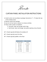
MINIMUM CLEARANCES TO COMBUSTIBLE MATERIALS /
ESPACES LIBRES MINIMUM DES MATÉRIAUX COMBUSTIBLES:
U.S. ENVIRONMENTAL PROTECTION AGENCY
This model is exempt from EPA certification under 40 CFR 60.531 by definition [Wood Heater (A) "Air-to-Fuel Ra
tio"].
7014-079
DO NOT REMOVE THIS LABEL / NE PAS ENLEVER L'ÉTIQUETTE
Made in China/Fait Aux Chine
1445 Highway North
Colville, WA 99114
www.quadrafire.com
A Back Wall to stove / Mur Arrière du poêle 2"/51mm
B Side Wall to Cast Top / Mur De Côté du haut 6"/152mm
CORNER INSTALLATION / NSTALLATION DU COIN :
C Side Wall / Mur De Côté 2"/51mm
VERTICAL ADAPTER KIT INSTALLATION:
UN ASSEMBLAGE POUR ADAPTEUR POUR INSTALLATION VERTICALE:
D Back Wall to Flue Pipe / Mur Arrière tuyau rigide 3"/76mm
B Side Wall to Cast Top / Mur De Côté du haut 6"/152mm
CORNER INSTALLATION WITH VERTICAL ADAPTER KIT:
INSTALLATION DU COIN AVEC UN ASSEMBLAGE D'ADAPTEUR VERTICAL:
E Side Wall / Mur De Côté 2"/51mm
ALCOVE INSTALLATION /
INSTALLATION DE L' ALCÔVE:
Max. Alcove Depth: / La profondeur maximum de l'alcôve 36"/914mm
A Back Wall to stove / Mur Arrière du poêle 2"/51mm
B Side Wall to Cast Top / Mur De Côté du haut 6"/152mm
C Unit corner to diagonal wall / 2" (51mm)
F Top of Unit to Combustibles / Du poêle du haut combustibles 12.5"/318mm
Alcove vertical installation / I
nstallation verticale de l'alcôve
D Back Wall to Flue Pipe / Mur Arrière tuyau rigide
3"/76mm
Floor protector must be noncombustible material, extending beneath heater and to the
front/sides/rear as indicated. Measure front distance (I) from the surface of the glass door.
G = 2"/51mm
H* = 2"/51mm
I = 6"/152mm
FLOOR PROTECTION / PROTECTION DU SOL
Note 1:
In residential installations, when using Parts 811-0580, (3" - 3" Top Vent Adapter) and
812-2690 (3" - 6" Top Vent Adapter Collar) 24 gauge 6" single wall flue connector may be used.
Note 1: Dans les installations résidentielles, lorsque les pièces 811-0580, (dessus de l'adapteur de
ventilation 3" - 3") et 812-2690 (collier de l'adapteur de ventilation 3" - 6"), un tuyau connecteur de 6"
pour mur simple de calibre 24 peut être utilisé.
Note 2: In manufactured home installation, when using Part 811-0580, (3" - 3" Top Vent Adapter) and
812-2690 (3' - 6" Top Vent Adapter Collar), use listed double wall flue connector. An Outside Air Kit
(Part 811-0560 rear or 811-0570 floor), must be used with manufactured home installation.
Note 2: Pour l'installation dans les maisons préfabriquées, lorsque les pièces 811-0580 (dessus de
l'adapteur de ventilation 3" - 3") et 812-2690 (collier de l'adapteur de ventilation 3" - 6"), utilisez un
tuyau connecteur enregistré pour mur double. Un assemblage d'air extérieur (pièce 811-0560 arrière
au 811-0570 la plancer), doit être utilisé pour l'installation dans les maisons préfabriquées.
*Non-combustible floor protection must extend beneath the flue pipe when installed with
horizontal venting or under the Top Vent Adapter with vertical installation.
RECOMMENDED IN USA; REQUIRED IN CANADA
Le poêle doit être placé sur une assise non combustible s’étendant tout autour de lui, comme les
schémas l’indiquent.
Mesurez la distance du devant (I) de la surface de la porte vitrée.
*Un protecteur incombustible de plancher doit s'étendre sous le conduit de cheminée pour une
installation de ventilation horizontale ou sous un adapteur de ventilation de dessus pour une
installation verticale. ÉTATS-UNIS - RECOMMANDÉ; CANADA - REQUIRENT
D
B
C
C
E
E
A
B
H*
G
G
I
A
B
C
C
F
A
D
2008 2009 2010 JAN FEB MAR APR MAY JUNE JULY AUG SEPT OCT NOV DEC
Listed Solid Fuel Room Heater/Pellet Type Insert. Also suitable for Mobile Home Installation. This appliance has
been tested and listed for use in Manufactured Homes in accordance with OAR 814-23-9000 through 814-23-909.
Tested to: ASTM E1509-95, ULC/ORD-C-1482-M1990, ULC S627-M93 Room Heating Pellet Burning Type,
APFI, (UM) 84-HUD FOR USE
ONLY WITH PELLETIZED WOOD OR SHELLED FIELD CORN FUEL.
Input Rating: 40,000 Btu's/hr
Electrical Rating:
115 VAC, 60 Hz, Start 4.6 Amps, Run 1.6 AMPS.
Route power cord away from unit. Do not route cord under or in front of appliance.
DANGER:
Risk of electrical shock. Disconnect power supply before servicing. Replace glass only with 5mm
ceramic available from your dealer. To start, set thermostat above room temperature, the stove will light
automatically. To shutdown, set thermostat to below room temperature. For further instruction refer to owner's
manual.
Keep viewing and ash removal doors tightly closed during operation.
Testé à: ASTM E1509-95, ULC/ORD-C 1482-M1990, ULC S627-M93 Room Heating. Pellet Burning Type, APFI, (UM)
84-HUD POUR USAGE AVEC LES BOULETTES DE BOIS OU DE COMBUSTIBLE DE MAIS ÉCOSSÉ DES CHAMPS.
Puissance de Rendement: 40,000 Btu's/hr
Puissance Électrique: 115 VAC, 60 Hz, Début 4.6 Amps, Courir 1.6 Amps,
Éloignez le fil électrique de l'appareil. Ne pas faire passer le fil électrique au dessus ou en dessous de l'appareil.
DANGER: Il y a risque de décharge électrique. Déconnectez le fil électrique de la prise de contact avant le service.
Remplacez la vitre seulement avec une vitre céramique de 5 mm disponible chez votre fournisseur.
Pour allumer, monter la température du thermostat au dessus de la température de la pièce, le poêle s'allumera
automatiquement. Pour éteindre, descendre la température du thermostat en dessous de la température de la pièce. Pour des
instructions supplémentaires, référez vous au manuel du propriétaire. Gardez la porte d'ouverture et la porte des cendres
fermées hermétiquement durant l'opération.
Appareil de chauffage inséré de combustible solide/de type de boulettes. Accepté dans l'installation dans les maisons mobiles. Cet
appareil a été testé et enregistré pour l'usage dans les Maisons Mobiles en accord avec OAR 814-23-9000 jusqu'à 814-23-
909.
R
Report / Rapport
061-S-21-4
CB 1200 Pellet Stove
SERIAL NO.
/ NUMÉRO DU
CAUTION:
HOT WHILE IN OPERATION DO NOT TOUCH. KEEP CHILDREN, CLOTHING AND FURNITURE AWAY. CONTACT MAY CAUSE
SKIN BURNS. SEE NAMEPLATE AND INSTRUCTIONS. Operate this unit with fuel hopper lid closed. Failure to do so may result in emissions
products' combustion from the hopper under certain conditions. Maintain hopper seal in good condition. Do no over fill the hopper.
ATTENTION:
CHAUD LORS DE L'OPÉRATION. NE PAS TOUCHER. GARDEZ LES ENFANTS ET LES VÊTEMENTS LOIN DE L'ESPACE DÉSIGNÉ DE L'INSTALLATION. LE
CONTACT PEUT CAUSER DES BRÛLURES À LA PEAU. VOIR L'ÉTIQUETTE ET LES INSTRUCTIONS. Opérez cet appareil avec le couvercle de la trémie fermé. Le défaut de ne
pas suivre les instructions peut résulter, sous certaines conditions, en une combustion des émissions des produits venant de la trémie. Ne pas remplir la trémie trop pleine.
007C
O-T L
Tested and
Listed by
Portland
Oregon USA
OMNI-Test Laboratories, Inc.
C
US
Testing Lab &
Report Number
Serial Number
Model
Mfg Date
R
September 1, 2008
7014-082D
Page 3
CB 1200 Pellet Stove
Section 1: Listing and Code Approvals
A. Appliance Certifications ......................4
B. Mobile Home Approved ......................4
C. Glass Specifications ............................4
D. Electrical Rating ..................................4
E. BTU & Efficiency Specifications ..........4
Section 2: Getting Started
A. Design, Installation & Location
Considerations ....................................5
B. Fire Safety ..........................................5
C. Tools & Supplies Needed ...................6
D. Inspect Appliance & Components.......6
Section 3: Dimensions & Clearances
A. Appliance Dimensions ........................7
B. Clearances to Combustibles ...............8
C. Hearth Requirements..........................9
Section 4: Vent Information
A. Chimney & Exhaust Connection .........10
B. Venting Termination Requirements ....10
C. Equivalent Feet of Pipe .......................11
D. Pipe Selection Chart ............................11
Section 5: Venting Systems
A. Alcove .................................................12
B. Through the Wall .................................13
C. Vertical ................................................14
D. Through the Wall & Vertical ................14
E. Masonry ..............................................15
F. Alternate Masonry ...............................15
Section 6: Mobile Home .................................. 16
Section 7: Appliance Set-Up
A. Outside Air Kit, Rear & Floor ..............17
B. Top Vent Adapter ...............................18
C.
Rear Vent & Rear to Top Vent Adapter
.18
D. Brick Set .............................................19
E. Brick Clip ............................................19
F. Log Set Placement ..............................20
G. Grille Assembly ...................................20
H. Logo Installation ..................................20
I. Door Installation ..................................21
J
. Thermostat Installation ........................21
Section 8: Operating Instructions
A. Fuel Size & Material ............................22
B. General Operation Information ...........22
C. Before Your First Fire .........................23
D. Starting Your First Fire ........................23
E. Fire Characteristics .............................23
F. Feed Rate Adjustment .......................23
G. Ignition Cycles ....................................24
H. Frequently Asked Questions...............24
Section 9: Troubleshooting ............................25-27
Section 10: Maintaining & Servicing Appliance
A. Proper Shutdown Procedures .............28
B. Quick Reference Maintenance Chart ..28
C. General Maintenance & Cleaning .......28-31
D. High Ash Fuel Content Maintenance ..32
E. Blower Replacement ...........................32-33
F. Baffle Removal ....................................33
G. Igniter Replacement ............................33
H. Glass Replacement .............................34
Section 11: Reference Material
A. Component Functions & Locations .....35-36
B. Component Locations (Drawings) ......37
C. Exploded Drawings .............................38-40
D. Service Parts & Accessories...............41-43
E. Service & Maintenance Log ................44
F. Homeowner’s Notes ...........................45
G. Warranty Policy ...................................46-47
H. Contact Information .............................48
TABLE OF CONTENTS
Page 4
7014-082D
September 1, 2008
R
CB 1200 Pellet Stove
1
Listing and Code Approvals
A. Appliance Certification
C. Glass Specifications
E. BTU & Efficiency Specifications
This appliance is equipped with 5mm ceramic glass. Replace
glass only with 5mm ceramic glass. Please contact your
dealer for replacement glass.
This appliance is approved for mobile home installations
when not installed in a sleeping room and when an outside
combustion air inlet is provided. The structural integrity of
the mobile home floor, ceiling, and walls must be maintained.
The appliance must be properly grounded to the frame of
the mobile home and use only Listed pellet vent Class “L”
or “PL” connector pipe. A Quadra-Fire Outside Air Kit must
be installed in a mobile home installation.
B. Mobile Home Approved
NOTE: This installation must conform with local codes. In
the absence of local codes you must comply with the ASTM
E1509, ULC S627-M93, ULC/ORD-C-1482-M1990, (UM)
84-HUD
D. Electrical Rating
115 VAC, 60 Hz, Start 4.1 Amps, Run 1.1 Amps
*BTU output will vary, depending on the brand of fuel you
use in your stove. Consult your Quadra-Fire dealer for
best results.
NOTE: Hearth & Home Technologies, manufacturer of
this appliance, reserves the right to alter its products,
their specifications and/or price without notice.
Emissions Rating 0.
.
9 grams/hr
*BTU Output 14,000 - 40,000 / hr
Heating Capacity up to 2,500 sq. ft. depending
on climate zone
Hopper Capacity 80 lbs
Fuel Wood Pellets or Shelled Corn
Shipping Weight 349 lbs
Model CB1200 Pellet Stove
Laboratory OMNI Test Laboratories, Inc.
Report No. 061-S-21-4
Type Solid Fuel Room Heater/Pellet Fuel
BurningType
Standard ASTM E1509-95, ULC S627-M93 and
ULC/ORD-C1482-M1990 Room Heater
Pellet Fuel Burning type and (UM) 84-
HUD, Mobile Home Approved.
State Listing Colorado, Listed 09-13-05
R
September 1, 2008
7014-082D
Page 5
CB 1200 Pellet Stove
2
Getting Started
A
. Design, Installation & Location
Considerations
B. Fire Safety
Maintain the designated clearances to combustibles. Insu-
lation must not touch the chimney. You must maintain the
designated air space clearance around the chimney. This
space around a chimney is necessary to allow natural heat
removal from the area. Insulation in this space will cause
a heat buildup, which may ignite wood framing. NOTE:
Clearances may only be reduced by means approved
by the regulatory authority having jurisdiction.
To provide reasonable fire safety, the following should be
given serious consideration:
1. Install at least one smoke detector on each floor of
your home to ensure your safety. They should be
located away from the heating appliance and close
to the sleeping areas. Follow the smoke detector
manufacturers placement and installation instructions,
and be sure to maintain regularly.
2. A conveniently located Class A fire extinguisher
to contend with small fires resulting from burning
embers.
3. A practiced evacuation plan, consisting of at least 2
escape routes.
4. A plan to deal with a hopper fire as follows:
In the event of a hopper fire:
a. Evacuate the house immediately.
b. Notify the fire department
CAUTION
Do NOT connect this unit to a chimney flue servicing
another appliance.
Do NOT connect to any air distribution duct or system.
Fire Hazard.
WARNING
Do not operate appliance before reading
and understanding operating instructions.
Failure to operate appliance properly may
cause a house fire.
1. Appliance Location
Consideration must be given to safety, convenience, traffic
flow, and the fact that the appliance will need a chimney and
chimney connector. It is a good idea to plan your installation
on paper, using exact measurements for clearances and floor
protection, before actually beginning the installation.
If you are not using an existing chimney, place the appliance
in a location to maintain a clear passage for the installation
of any listed and approved pellet venting system. This appli-
ance may be vented vertically or horizontally.
Maintain specified vent clearance to comubstible require-
ments listed by the pellet manufactures venting instructions
and all clearance to combustivles listed in this manual.
Check with your local building code agency before you begin
your installation. Be sure local building codes do not super-
sede UL specifications and always obtain a building permit
so that insurance protection benefits cannot be unexpectedly
cancelled. If any assistance is required during installation,
please contact your local dealer.
We recommend that a qualified building inspector and your
insurance company representative review your plans before
and after installation.
2. Thermostat Location
The thermostat’s location will have some effect on the
appliance’s operation. When the thermostat is located close
to the appliance, it may require a slightly higher temperature
setting to keep the rest of the house comfortable. If the
thermostat location is in an adjacent room or on a different
floor level, you will notice higher temperatures near the
appliance.
Page 6
7014-082D
September 1, 2008
R
CB 1200 Pellet Stove
D. Inspect Appliance & Components and
Pre-Use Check List
Reciprocating Saw
Channel Locks
Hammer
Phillips Screwdriver
Tape Measure
Plumb Line
Level
Framing Material
Hi-temp Caulking Material
Gloves
Safety Glasses
Framing Square
Electric Drill & Bits (1/4”)
1/4” Self-Tapping Screws
May also need:
Vent Support Straps
Venting Paint
Tools and building supplies normally required
for installation, unless installing into an existing
masonry fireplace:
C. Tools And Supplies Needed
Inspect appliance and components for
damage. Damaged parts may impair safe
operation.
WARNING
Do NOT install damaged components.
Do NOT install incomplete components.
Do NOT install substitute components.
Report damaged parts to dealer.
1. Place the appliance in a location near the
final installation area and follow the proce-
dures below:
2. Open the appliance and remove all the parts
and articles packed inside the Component
Pack. Inspect all the parts and glass for ship-
ping damage. Contact your dealer if any irregu-
larities are noticed.
3. All safety warnings have been read and fol-
lowed.
4. This Owners Manual has been read.
5. Floor protection requirements have been met.
6. Venting is properly installed.
7. The proper clearances from the appliance and
chimney to combustible materials have been
met.
8. The masonry chimney is inspected by a profes-
sional and is clean, or the factory built metal
chimney is installed according to the manufac-
turers instructions and clearances.
9. The chimney meets the required minimum
height.
10.
All labels have been removed from the glass
door.
11. Plated surfaces have been wiped clean, if
applicable.
12. Thermostat or remote has been installed.
13.
A power outlet is available nearby.
Installation and use of any damaged appliance.
Modification of the appliance.
Installation other than as instructed by Hearth & Home
Technologies.
Installation and/or use of any component part not approved
by Hearth & Home Technologies.
Operating appliance without fully assembling all
components.
Operating appliance without legs attached (if supplied with
unit).
Do NOT Overfire
Or any such action that may cause a fire hazard.
WARNING
Hearth & Home Technologies disclaims any
responsibility for, and the warranty will be
voided by, the following actions:
Fire Risk.
R
September 1, 2008
7014-082D
Page 7
CB 1200 Pellet Stove
3
Dimensions and Clearances
A. Appliance Dimensions
5.0 in
(127mm)
4-5/8 in
(118mm)
12-3/8 in
(314mm)
14-1/4 in
(362mm)
2-1/2 in
(64mm)
C
L
8-1/6 in.
(205mm)
20- 7/16 in.
(519mm)
28-1/2 in. (724mm)
27-5/8 in.
(692mm)
25-3/4 in.
(654mm)
C
L
10-3/4 in.
(273mm)
24-3/4 in.
(629mm)
25-3/4 in.
(629mm)
8-1/16 in.
(205mm)
C
L
28-1/2 in.
(724mm)
26-1/2 in.
(673mm)
31-5/8 in.
(803mm)
Figure 7.4 - Front View
Figure 7.1 - Top View
Figure 7.3 - Side View
Figure 7.2 - Top View with Top Vent Adapter
Page 8
7014-082D
September 1, 2008
R
CB 1200 Pellet Stove
Straight Back Against
Wall
Inches Millimeters
A
Back Wall to Appliance 2 51
B
Side Wall to Appliance 6 152
Corner Installation
Inches Millimeters
C
Walls to Appliance 2 51
Vertical Installation
Inches Millimeters
D
Back Wall to Flue Pipe 3 76
E
Side Wall to Top 6 152
F
Back Wall to Appliance 7.5 191
Installations with:
3 to 3 inch Top Vent Adapter and
3 to 6 inch Offset Adapter Kit
Corner Installation
Inches Millimeters
G
Walls to Appliance 2 51
B. Clearances to Combustibles (UL and ULC)
D
E
F
A
B
Fire Risk.
Comply with all minimum clearances to
combustibles as specified.
WARNING
Failure to comply may cause house fire.
NOTE:
Illustrations reflect typical installations and are FOR
DESIGN PURPOSES ONLY.
Illustrations/diagrams are not drawn to scale.
Actual installation may vary due to individual design
preference.
C
C
G
G
Alcove Installation
Inches Millimeters
Minimum Alcove Height 44 1117
Minimum Alcove Width 40-1/2 1029
Maximum Alcove Depth 36 915
Minimum Alcove Side Wall 6 152
Top of Unit to Combustibles 12-1/2 318
R
September 1, 2008
7014-082D
Page 9
CB 1200 Pellet Stove
*L Exception for Horizontal Installations:
USA INSTALLATIONS: A
non-combustible floor protec-
tion is recommended extending beneath the flue pipe
when installed with horizontal venting or under the top
vent adapter with vertical installation.
CANADA INSTALLATIONS: A
non-combustible floor
protection extending beneath the flue pipe is r
equired
with horizontal venting or under the top vent adapter with
vertical installation.
Must extend 2 inches (51mm) beyond each
side of pipe (shaded area)
C. Hearth Pad Requirements (UL and ULC)
L*
K
K
M
Use a non-combustible floor protector, extending beneath
appliance and to the front, sides and rear as indicated.
Measure front distance “M” from the surface of the glass
door.
Hearth Pad Requirements
Inches Millimeters
K
Sides 2 51
L*
Back 2 51
M
Front 6 152
Figure 9.1
Figure 9.2
Page 10
7014-082D
September 1, 2008
R
CB 1200 Pellet Stove
Do not terminate vent in any enclosed or semi-enclosed
area such as a carport, garage, attic, crawl space, under a
sun deck or porch, narrow walkway or closely fenced area,
or any location that can build up a concentration of fumes
such as a stairwell, covered breezeway, etc.
CAUTION
Vent surfaces get HOT, can cause burns if
touched. Noncombustible shielding or guards
may be required.
WARNING
A. Chimney and Exhaust Connection
1. Chimney & Connector: Use 3 or 4 inch (76-102mm)
diameter type "L" or "PL" venting system. It can be
vented vertically or horizontally.
2. Mobile Home: Approved for all Listed pellet vent. If
using the 3 inch (76mm) vertical top vent adapter Kit
or the 3 to 6 inch (76-152mm) top vent offset adapter,
use Listed double wall flue connector. A Quadra-Fire
outside air kit must be used with manufactured home
installations.
3. Residential: The 3 inch (76mm) vertical top vent
adapter kit and the 3 to 6 inch (76-152mm) top vent
offset adapter are tested to use 24 gauge single wall flue
connector or Listed double wall flue connector to Class
A Listed metal chimneys, or masonry chimneys meeting
national and/or local codes for solid fuel appliances.
4. INSTALL VENT AT CLEARANCES SPECIFIED BY THE
VENT MANUFACTURER.
5. Secure exhaust venting system to the appliance with at
least 3 screws. Also secure all connector pipe joints with
at least 3 screws through each joint.
NOTE: All pipe must be welded seam pipe whenever
possible. Seal pipe joints with high temperature silicone
(500°F [260°C] minimum rated only).
NOTE: If burning shelled field corn, you must use
approved venting specifically designed for corn. Follow
the instructions from the venting manufacturer.
Fire Hazard.
Only LISTED venting components may be
used.
NO OTHER vent components may be used.
Substitute or damaged vent components may
impair safe operation.
WARNING
B. Venting Termination Requirements
1. Termination must exhaust above air inlet elevation. It is
recommended that at least 60 inches (1524mm) of verti-
cal pipe be installed when appliance is vented directly
through a wall. This will create a natural draft, which
will help prevent the possibility of smoke or odor venting
into the home during a power outage. It will also keep
exhaust from causing a nuisance or hazard by exposing
people or shrubs to high temperatures. The safest and
preferred venting method is to extend the vent vertically
through the roof.
2. Distance from doors and opening windows, or gravity or
ventilation air inlets into building:
a. Not less than 48 inches (1219mm) below;
b. Not less than 48 inches (1219mm) horizontally
from;
c. Not less than 12 inches (305mm) above.
3. Distance from permanently closed windows:
a. Not less than 12 inches (305mm) below, horizontally
from or above.
4. Distance between bottom of termination and grade
should be 12 inches (305mm) minimum. This is con-
ditional upon plants in the area, and nature of grade
surface. The grade surface must be a non-combustible
material (i.e., rock, dirt). The grade surface must not be
lawn. Distance between bottom of termination and public
walkway should be 84 inches (2134mm) minimum.
5. Distance to combustible materials must be 24 inches
(610mm) minimum. This includes adjacent buildings,
fences, protruding parts of the structure, roof overhang,
plants and shrubs, etc.
6. Termination Cap Location (Home Electrical Service)
Side-to-side clearance is to be the same as minimum
clearance to vinyl inside corners.
Clearance of a termination cap below electrical service
shall be the same as minimum clearance to vinyl soffits.
Clearance of a termination cap above electrical service
will be 12 inches (305mm) minimum.
Location of the vent termination must not obstruct or
interfere with access to the electrical service.
4
Vent Information
R
September 1, 2008
7014-082D
Page 11
CB 1200 Pellet Stove
Improper installation, adjustment, alteration, service or
maintenance can cause injury or property damage. Refer
to the owners information manual provided with this appli-
ance. For assistance or additional information consult a
qualified installer, service agency or your dealer.
WARNING
The chart will help you in determining proper
venting size according to the equivalent feet of
pipe calculated above and the altitude above sea
level of this installation. Figure 11.2.
Locate the calculated equivalent feet of pipe on
the vertical left side of the chart. Move to the
right horizontally on the chart until you reach
your altitude above sea level.
If you fall below the diagonal line, 3 or 4 inch (76
to 102mm) pipe may be used. If it is anywhere
above the diagonal line, a 4 inch (102mm) diam-
eter pipe is required.
The chart reveals that a 90° elbow is 5 times as
restrictive to the flow of exhaust gases under
positive pressure as 1 foot of horizontal pipe, and
a foot of horizontal pipe is twice as restrictive as
a foot of vertical pipe.
D. Pipe Selection Chart
The table below can help you calculate the equivalent feet
of pipe which is a method used to determine pellet vent size.
Figure 11.1.
C. Equivalent Feet of Pipe
2 ft.
2 ft.
3 ft.
2 ft.
Example of 3 Elbow-Rear Vent Termination Calculaton
Figure 11.1
Pellet Venting
Component
# of
Elbows
Feet of
Pipe
Multipled
By
Equivalent
Feet
Components
Equivalent Feet
90
o
Elbow or Tee
3X5 15
45
o
Elbow
X 3
Horizontal Pipe
7X 1 7
Vertical Pipe
2X 0.5 1
Total Equivalent Feet 23
Note: This is a generic example and is not
intended to represent any specific fuel type.
Fire Risk.
Do NOT pack insulation or other
combustibles between firestops.
• ALWAYS maintain specified clearances
around venting and firestop systems.
Install firestops as specified.
Failure to keep insulation or other material
away from vent pipe may cause fire.
WARNING
3 in. or 4 in. (76mm or 102mm) Diameter Pipe
Equivalent Pipe
Length In Feet
ALTITUDE IN THOUSANDS OF FEET
0
20
30
1 2 3 4 5 6 7 8 9 10
4 in. (102mm) Diameter Pipe Only
10
Example 1
Example 2
Figure 11.2
Example 1: If the equivalent length of pipe is 23
feet with altitude of 8,000 feet you must use 4 inch
(102mm) diameter type “L” or “PL” vent.
Example 2: If the equivalent length of pipe is 12 feet
with altitude of 6,000 feet you may use 3 or 4 inch (76
to 102mm) diameter type “L” or “PL” vent
Page 12
7014-082D
September 1, 2008
R
CB 1200 Pellet Stove
5
Venting Systems
NOTE:
Illustrations reflect typical installations and are FOR
DESIGN PURPOSES ONLY.
I
llustrations/diagrams are not drawn to scale.
Actual installation may vary due to individual design
preference.
A. Alcove
Figure 12.1
All minimums listed are to a combustible surface.
A
C
B
D
Alcove Installation
Inches Millimeters
A
Minimum Alcove Height 44 1117
B
Minimum Alcove Width 40-1/2 1029
C
Maximum Alcove Depth 36 915
D
Minimum Alcove Side Wall 6 152
not shown Top of Unit to Combustibles 12-1/2 318
R
September 1, 2008
7014-082D
Page 13
CB 1200 Pellet Stove
12 in.
(305mm)
Minimum
Non-combustible Hearth Pad
Wall
Thimble
Horizontal
Termination
Cap
2 in.
(51mm)
Minimum
6 in.
(152mm)
Minimum
From Glass
Straight Out
B. Through The Wall
Horizontal termination cap must be a minimum of 12 inches.
(305mm) from the wall. Approved for mobile home instal-
lations. Must use 3 or 4 inch (76-102mm) “L” or “PL” listed
pellet venting or listed double wall pipe and a Quadra-Fire
outside air kit in mobile homes.
NOTE:
In Canada, where passage through a wall or partition of
combustible construction is desired, the installation shall
conform to CAN/CSA-B365
Figure 13.1
Figure 13.2
Wall
Thimble
Illustration shows venting going in both directions.
Choose which one is best for your installation.
2 in. (51mm)
Minimum
2 in. (51mm)
Minimum
12 in.
(305mm)
Minimum
12 in. (305mm)
Minimum
45 Degree
Page 14
7014-082D
September 1, 2008
R
CB 1200 Pellet Stove
We recommend a minimum of 60 in.
(1524mm) vertical, however above the eave
is preferred.
Both installations are approved for mobile
home installations. Must use 3 or 4 inch (76
to 102mm) “L” or “PL” Listed pellet venting or
listed double wall pipe and Quadra-Fire out-
side air kit in mobile homes. Single wall pipe
is approved for residential installations only.
C. Vertical
D. Through The Wall & Vertical
Firestop
Flashing
Rain Cap
6 in.
(152mm)
Min.
Non-combustible Hearth Pad
3 in. (76mm)
Min.
Clean-out
Cover
24 in. (610mm)
minimum
Ceiling Support
Class A Chimney
Connector Adapter
Top Vent Kit
Non-Combustible Hearth Pad
Clean-out Cover
Te e
Wall Thimble
Support Bracket
every 60 in. (1524mm)
24 in. (610mm)
Minimum
Rain Cap
Flashing
2 in. (51mm) Minimum
6 in. (152mm)
Minimum
Figure 14.1
Figure 14.2
R
September 1, 2008
7014-082D
Page 15
CB 1200 Pellet Stove
Fire Hazard
Inspection of Chimney:
Masonry chimney must be in good condition.
Meets minimum standard of NFPA 211
Factory-built chimney must be 6 in. (152mm) UL103 HT.
WARNING
E. Masonry
F. Alternate Masonry
Non-Combustible Hearth Pad
Airtight
Clean-out Door
Cleanout Cover
Sheathing
3 in. (76mm) Minimum
1 in. (25mm) Clearance
Flashing
Fireclay Flue
Liner with Airspace
Concrete Cap
1 in. (25mm) Clearance
with Firestop
6 in. (152mm)
Minimum
Non-Combustible Hearth Pad
Sheathing
2 in. (51mm) Minimum
1 in. (25mm)
Clearance
Flashing
Fireclay Flue Liner
with Airspace
Concrete Cap
6 in. (152mm)
Minimum
Airtight Clean-out Door
1 in. (25mm) Clearance
with Firestop
Figure 15.1
Figure 15.2
Page 16
7014-082D
September 1, 2008
R
CB 1200 Pellet Stove
6
Mobile Home
1. An outside air inlet must be provided for the combustion
air and must remain clear of leaves, debris, ice and/or
snow. It must be unrestricted while the appliance is
in use to prevent room air starvation which causes
smoke spillage. Smoke spillage can also set off smoke
alarms.
2. The combustion air duct system must be made of
metal. It must permit zero clearance to combustible
construction and prevent material from dropping into
the inlet or into the area beneath the dwelling and
contain a rodent screen.
3. The appliance must be secured to the mobile home
structure by bolting it to the floor (using lag bolts).
Use the same holes that secured the appliance to the
shipping pallet.
4. The appliance must be grounded with #8 solid copper
grounding wire or equivalent, terminated at each end
with an NEC approved grounding device.
5. Refer to Clearances to Combustibles and floor pro-
tection requirements on pages 8 & 9 for listings to
combustibles and appropriate chimney systems.
6. Use silicone to create an effective vapor barrier at
the location where the chimney or other component
penetrates to the the exterior of the structure.
7. Follow the chimney manufacturer’s instructions when
installing the vent system for use in a mobile home.
8. Installation shall be in accordance with the Manufactur-
ers Home & Safety Standard (HUD) CFR 3280, Part
24.
CAUTION
Maintain structural integrity of mobile home:
Floor, wall, ceiling and/or roof.
Do NOT cut through:
Floor joist, wall, studs or ceiling trusses.
Any supporting material that would affect the structural
integrity.
Never install in a sleeping room.
WARNING
Installation must comply with Manufactured Home and
Safety Standard (HUD), CFR 3280, Part 24.
WARNING
You must use a Quadra-Fire Outside Air Kit
for installation in a mobile home.
A. Mobile Home Installation
Figure 16.1
CAUTION
Never draw outside combustion air from:
Wall, floor or ceiling cavity
Enclosed space such as an attic or garage
Spark Arrestor Cap
Roof Flashing
Storm Collar
Joist Shield/Firestop
Approved Class “L”
o
“PL” Pellet Vent
R
September 1, 2008
7014-082D
Page 17
CB 1200 Pellet Stove
7
Appliance Set-Up
A. Outside Air Kit Instructions
Flex Hose
Hose Clamp
Collar Assembl
y
Trim Ring
Termination
Cap Assembly
Hose Clamp
Included in Kit: 1 piece of 2 inch x 3 foot flex hose, 2 hose
clamps, 1 collar assembly, termination cap assembly, 1
trim ring, 12 screws.
a. Measure distance from floor to air vent opening in appli
-
ance and mark location on wall.
Use saw to cut opening in wall. Cut a 2-1/2 to 3 inch
(64-76mm) opening on inside wall and a 3 to 3-1/2 inch
(76-89mm) opening on outside of house.
b. Use hose clamp to secure flex pipe to collar assembly.
c. Slide trim ring over flex pipe and run pipe through wall.
d. Attach hose to outside termination cap with second
hose clamp.
e. Secure termination cap to outside surface.
f. Secure trim ring to interior wall.
g. Snip corners and remove plate. Figure 17.1.
h. Align and secure collar assembly with 2 of the 4 holes
as shown. Figure 17.2.
Tools Needed: Phillips head screw driver; wire cutters;
hole saw or jig saw.
CAUTION
Never draw outside combustion air from:
Wall, floor or ceiling cavity
Enclosed space such as an attic or garage
Figure 17.1
1. Rear Installation
Snip Corners
and remove
plate
Figure 17.2
Figure 17.3
a. Remove rear screen and set aside.
b. Install cover plate over hole in right rear floor.
c. Cut a 2 inch minimum hole in the floor to accommodate
flex hose.
d. Attach hose to termination cap.
e. Place rope under pedestal to close off air leaks.
Screen
Install Cover Plate
Seal Pedestal with 26 in. Rope
Figure 17.4
2. Floor Installation
NO
NO
Secure Collar
Page 18
7014-082D
September 1, 2008
R
CB 1200 Pellet Stove
3 to 3 inch Top Vent Adapter
3 to 6 inch Top Vent Offset Adapter
1. Put a layer of high temperature silicone on the 3 inch
(76mm) exhaust outlet.
2. Slide the top vent adapter onto the rear exhaust outlet
and adjust the assembly to a vertical position.
3. Drill 4 holes with #26 drill bit (provided) into the back of
the appliance using the outer shield as a pattern (make
sure the assembly is vertical). Figure 18.1
4. Install the 4 mounting screws.
5. Install the vent pipe into the top vent adapter (be sure
to silicone all joints).
6 To clean the top vent adapter, open the clean-out cover.
See Figure 18.1
B. Top Vent Adapter Installation
Installing the Top Vent Adapter
3" - 6"
Offset
Adapter
3" - 3"
Top Vent
Adapter
Drill holes in back of
stove and secure with 4
screws, 2 on each side.
Clean Out
Cover
Figure 18.1
C. Rear Vent and Rear Vent to Top Vent
Adapter Installation
Clean-Out Cover
Clean-Out Cover
Figure 18.2 - Rear Vent Adapter
Figure 18.3 - Rear to Top Vent Adapter - 90
o
1. Put a layer of high temperature silicone on the 3 inch
(76mm) exhaust outlet.
2. Slide the adapter onto the rear exhaust outlet and adjust
the assembly to the appropriate position.
3. Install the vent pipe into the adapter (be sure to silicone
all joints)
R
September 1, 2008
7014-082D
Page 19
CB 1200 Pellet Stove
D. Optional Brick Set Installation
1. Remove the baffle first, follow instructions on page 33.
2. Slide bottom of left rear brick in first; rotate top edge
toward rear of appliance and then rotate outer edge
toward rear of appliance, until brick slides into place.
Figure 19.1.
3. Repeat with right rear brick.
4. Place left side brick along left side of firebox, making sure
chamfered (beveled) back edge of brick fits snugly next
to rear brick. Figure 19.2.
5. Repeat with right side panel.
6. Complete brick set, correctly installed. Figure 19.3.
1
2
3
1
2
3
4
Figure 19.1
Figure 19.2
Figure 19.3
1. After the brick set has been installed, 2 brick clips need
to be installed on the outer edge of each baffle to hold
the brick set in place.
2. Remove 2 baffles from the appliance. Slide the baffle up
and the bottom edge should fall down and then lift the
baffle out.
3. Using pliers, bend the brick clip slightly past 90° in the
direction shown in Figure 19.4.
4. Position the brick clip as shown in Figure 19.4 and use
pliers to crimp around the outside edge of the baffle as
shown in Figure 19.5.
Note: Figure 19.5 shows the finished shape of the brick
clip, after being bent around the outside edge of
the baffle.
5. Slide the baffle back into place making sure that the brick
clip holds the side brick toward the wall of the firebox.
Push back on the sides so they will keep the rear bricks
in place. Repeat for opposite side.
Approximately
1 inch from corner
Top outside
corner of Baffle
Outside edge
of Baffle
Use pliers to crimp
Brick Clip around edge
Installed Clip
E. Brick Clip Installation
Brick may have small wires protruding from
the back of brick.
WARNING
Risk of Injury.
Figure 19.4
Figure 19.5
1
Page 20
7014-082D
September 1, 2008
R
CB 1200 Pellet Stove
G. Optional Gold or Nickel Grille Assembly
1. Place the front log in first as shown in Figure 20.1. Place
log between firepot and face of appliance with charred
area surrounding firepot.
2. Set the left and right logs onto the front log, placing
the holes in the base of the left and right logs over the
locating pins in front log. See Figure 20.2. Ensure that
the charred ends are facing the firepot.
F. Optional Log Set Placement Instructions
CAUTION
Logs are FRAGILE. Use extreme care when handling or
cleaning logs.
NOTE:
Due to the abrasive nature of a pellet appliance fire, the
logs are not covered under warranty. Any placement varia-
tion other than shown here can cause excessive heat and
shall void the appliance warranty.
LOCATING PINS
Charred Areas in the Back
Top Log
Right
Top Log, Left
Front Log
Figure 20.1
Figure 20.2
Place 1 flap of
box lid into
opening for
stability
CAUTION: Do not open top all the way back so the weight is
supported by the hinges. It will damage the hinges. Prop the
top up with supporting brace or use shipping box as shown.
Align the 3 hoes in the stove
with the holes in the grille and
secure in place.
1. Remove grille from packaging.
2. Lift top up and place shipping box in vertically.
3. Place 1 flap of the box lid into opening for stability.
4. Align the 3 holes in the stove with the holes in the grille.
5. Use a Phillips screwdriver to secure in place.
6. Remove shipping box and lower top.
Install Logo
1. Remove logo from packaging.
2. The logo has 2 studs on the back.
3. Install the logo on the lower left side of the center
panel by pressing the 2 studs into the pre-drilled
holes. See Figure 20.4.
Do not open top all the way back so the weight of the
top is supported by the hinges. It will damage the
hinges. It will be necessary to prop the top up with
a supporting brace. You can use the shipping box as
shown in Figure 1.
CAUTION
Figure 20.3
H. Installing Logo (Nickel Only)
Figure 20.4
  • Page 1 1
  • Page 2 2
  • Page 3 3
  • Page 4 4
  • Page 5 5
  • Page 6 6
  • Page 7 7
  • Page 8 8
  • Page 9 9
  • Page 10 10
  • Page 11 11
  • Page 12 12
  • Page 13 13
  • Page 14 14
  • Page 15 15
  • Page 16 16
  • Page 17 17
  • Page 18 18
  • Page 19 19
  • Page 20 20
  • Page 21 21
  • Page 22 22
  • Page 23 23
  • Page 24 24
  • Page 25 25
  • Page 26 26
  • Page 27 27
  • Page 28 28
  • Page 29 29
  • Page 30 30
  • Page 31 31
  • Page 32 32
  • Page 33 33
  • Page 34 34
  • Page 35 35
  • Page 36 36
  • Page 37 37
  • Page 38 38
  • Page 39 39
  • Page 40 40
  • Page 41 41
  • Page 42 42
  • Page 43 43
  • Page 44 44
  • Page 45 45
  • Page 46 46
  • Page 47 47
  • Page 48 48

Hearth and Home Technologies Stove CB1200-B User manual

Category
Stoves
Type
User manual
This manual is also suitable for

Ask a question and I''ll find the answer in the document

Finding information in a document is now easier with AI