Asus P4B-E User manual
- Category
- Server/workstation motherboards
- Type
- User manual

Motherboard
®
P4B-E
User Guide

ii
Checklist
Copyright © 2001 ASUSTeK COMPUTER INC. All Rights Reserved.
No part of this manual, including the products and software described in it, may be
reproduced, transmitted, transcribed, stored in a retrieval system, or translated into any
language in any form or by any means, except documentation kept by the purchaser for
backup purposes, without the express written permission of ASUSTeK COMPUTER INC.
(“ASUS”).
Product warranty or service will not be extended if: (1) the product is repaired, modified or
altered, unless such repair, modification of alteration is authorized in writing by ASUS; or (2)
the serial number of the product is defaced or missing.
ASUS PROVIDES THIS MANUAL “AS IS” WITHOUT WARRANTY OF ANY KIND, EITHER
EXPRESS OR IMPLIED, INCLUDING BUT NOT LIMITED TO THE IMPLIED WARRANTIES
OR CONDITIONS OF MERCHANTABILITY OR FITNESS FOR A PARTICULAR PURPOSE.
IN NO EVENT SHALL ASUS, ITS DIRECTORS, OFFICERS, EMPLOYEES OR AGENTS BE
LIABLE FOR ANY INDIRECT, SPECIAL, INCIDENTAL, OR CONSEQUENTIAL DAMAGES
(INCLUDING DAMAGES FOR LOSS OF PROFITS, LOSS OF BUSINESS, LOSS OF USE
OR DATA, INTERRUPTION OF BUSINESS AND THE LIKE), EVEN IF ASUS HAS BEEN
ADVISED OF THE POSSIBILITY OF SUCH DAMAGES ARISING FROM ANY DEFECT OR
ERROR IN THIS MANUAL OR PRODUCT.
SPECIFICATIONS AND INFORMATION CONTAINED IN THIS MANUAL ARE FURNISHED
FOR INFORMATIONAL USE ONLY, AND ARE SUBJECT TO CHANGE AT ANY TIME
WITHOUT NOTICE, AND SHOULD NOT BE CONSTRUED AS A COMMITMENT BY ASUS.
ASUS ASSUMES NO RESPONSIBILITY OR LIABILITY FOR ANY ERRORS OR
INACCURACIES THAT MAY APPEAR IN THIS MANUAL, INCLUDING THE PRODUCTS
AND SOFTWARE DESCRIBED IN IT.
Products and corporate names appearing in this manual may or may not be registered
trademarks or copyrights of their respective companies, and are used only for identification or
explanation and to the owners’ benefit, without intent to infringe.
E862
First Edition October 2001

iii
Features
Contents
FCC/CDC statements .....................................................................vi
Safety information .......................................................................... vii
About this guide ............................................................................ viii
How this guide is organized.................................................. viii
Conventions used in this guide...............................................ix
Where to find more information .............................................. ix
ASUS contact information ................................................................x
Chapter 1: Product introduction ......................................... 1-1
1.1 Welcome!............................................................................ 1-1
1.2 Package contents ............................................................... 1-1
1.3 Overview............................................................................. 1-2
1.3.1 Identifying the motherboard components ................ 1-2
1.3.2 Pre-installed accessory........................................... 1-6
1.4 Special features .................................................................. 1-6
1.4.1 Product highlights ................................................... 1-6
1.4.2 Value-added solutions ............................................ 1-8
Chapter 2: Hardware information ........................................ 2-1
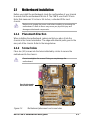
2.1 Motherboard installation ...................................................... 2-1
2.1.1 Placement direction ................................................ 2-1
2.1.2 Screw holes............................................................ 2-1
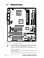
2.2 Motherboard layout ............................................................. 2-2
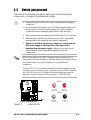
2.3 Before you proceed............................................................. 2-3
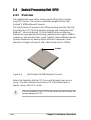
2.4 Central Processing Unit (CPU) ............................................ 2-4
2.4.1 Overview ................................................................ 2-4
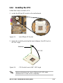
2.4.2 Installing the CPU ................................................... 2-5
2.4.3 Installing the heatsink and fan................................. 2-7
2.4.4 Connecting the CPU fan cable................................ 2-9
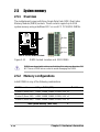
2.5 System memory ................................................................ 2-10
2.5.1 Overview .............................................................. 2-10
2.5.2 Memory configurations ......................................... 2-10
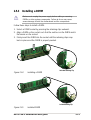
2.5.3 Installing a DIMM ...................................................2-11
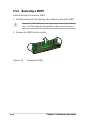
2.5.4 Removing a DIMM................................................ 2-12

iv
Safeguards
Contents
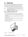
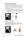
2.6 Expansion slots................................................................. 2-13
2.6.1 Installing an expansion card.................................. 2-13
2.6.2 Configuring an expansion card ............................. 2-14
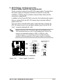
2.6.3 PCI slots ............................................................... 2-15
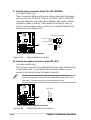
2.6.4 AGP slot ............................................................... 2-15
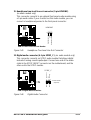
2.6.5 CNR slot............................................................... 2-16
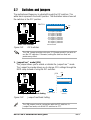
2.7 Switches and jumpers ....................................................... 2-17
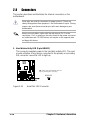
2.8 Connectors ....................................................................... 2-26
Chapter 3: Powering up ....................................................... 3-1
3.1 Starting up for the first time.................................................. 3-1
3.2 Vocal POST Messages ....................................................... 3-2
3.3 Powering off the computer................................................... 3-4
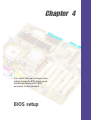
Chapter 4: BIOS setup ......................................................... 4-1
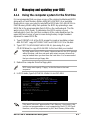
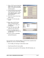
4.1 Managing and updating your BIOS...................................... 4-1
4.1.1 Using the computer system for the first time ........... 4-1
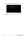
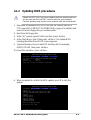
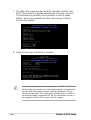
4.1.2 Updating BIOS procedures ..................................... 4-3
4.2 BIOS Setup program........................................................... 4-5
4.2.1 BIOS menu bar....................................................... 4-6
4.2.2 Legend bar ............................................................. 4-6
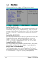
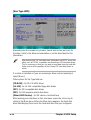
4.3 Main Menu .......................................................................... 4-8
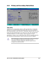
4.3.1 Primary and Secondary Master/Slave ..................... 4-9
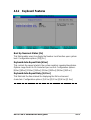
4.3.2 Keyboard Features ............................................... 4-13
4.4 Advanced Menu ................................................................ 4-15
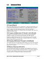
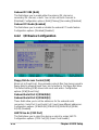
4.4.1 Chip Configuration ................................................ 4-17
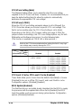
4.4.2 I/O Device Configuration....................................... 4-20
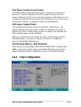
4.4.3 PCI Configuration ................................................. 4-22
4.5 Power Menu...................................................................... 4-24
4.5.1 Power Up Control ................................................. 4-26
4.5.2 Hardware Monitor ................................................. 4-28
4.6 Boot Menu ........................................................................ 4-29
4.7 Exit Menu.......................................................................... 4-31

v
Contents
Chapter 5: Software support ............................................... 5-1
5.1 Install an operating system.................................................. 5-1
5.1.1 Windows 98 first time installation ............................ 5-1
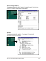
5.2 Support CD information....................................................... 5-1
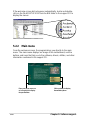
5.2.1 Running the support CD ......................................... 5-1
5.2.2 Main menu ............................................................. 5-2
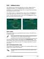
5.2.3 Software menu ....................................................... 5-3
5.2.4 Drivers menu .......................................................... 5-5
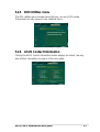
5.2.5 DOS Utilities menu ................................................. 5-7
5.2.6 ASUS Contact Information...................................... 5-7
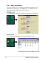
5.2.7 Other information .................................................... 5-8
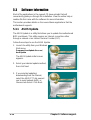
5.3 Software information ......................................................... 5-10
5.3.1 ASUS Update ....................................................... 5-10
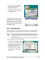
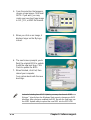
5.3.2 ASUS MyLogo™ ...................................................5-11
5.3.3 Personalized Boot Logo........................................ 5-13
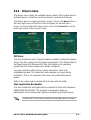
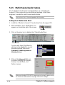
5.3.4 Winbond Voice Editor ........................................... 5-14
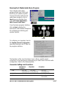
5.3.5 Multi-Channel Audio Feature ................................ 5-18
Index ........................................................................................ I-1

vi
FCC/CDC statements
Federal Communications Commission Statement
This device complies with FCC Rules Part 15. Operation is subject to the
following two conditions:
• This device may not cause harmful interference, and
• This device must accept any interference received including interference
that may cause undesired operation.
This equipment has been tested and found to comply with the limits for a
Class B digital device, pursuant to Part 15 of the FCC Rules. These limits
are designed to provide reasonable protection against harmful interference
in a residential installation. This equipment generates, uses and can radiate
radio frequency energy and, if not installed and used in accordance with
manufacturer’s instructions, may cause harmful interference to radio
communications. However, there is no guarantee that interference will not
occur in a particular installation. If this equipment does cause harmful
interference to radio or television reception, which can be determined by
turning the equipment off and on, the user is encouraged to try to correct the
interference by one or more of the following measures:
• Reorient or relocate the receiving antenna.
• Increase the separation between the equipment and receiver.
• Connect the equipment to an outlet on a circuit different from that to
which the receiver is connected.
• Consult the dealer or an experienced radio/TV technician for help.
The use of shielded cables for connection of the monitor to the
graphics card is required to assure compliance with FCC regulations.
Changes or modifications to this unit not expressly approved by the
party responsible for compliance could void the user’s authority to
operate this equipment.
Canadian Department of Communications Statement
This digital apparatus does not exceed the Class B limits for radio noise
emissions from digital apparatus set out in the Radio Interference
Regulations of the Canadian Department of Communications.
This class B digital apparatus complies with Canadian ICES-003.

vii
Safety information
Electrical safety
• To prevent electrical shock hazard, disconnect the power cable from
the electrical outlet before relocating the system.
• When adding or removing devices to or from the system, ensure that
the power cables for the devices are unplugged before the signal
cables are connected. If possible, disconnect all power cables from the
existing system before you add a device.
• Before connecting or removing signal cables from the motherboard,
ensure that all power cables are unplugged.
• Seek professional assistance before using an adpater or extension
cord. These devices could interrupt the grounding circuit.
• Make sure that your power supply is set to the correct voltage in your
area. If you are not sure about the voltage of the electrical outlet you
are using, contact your local power company.
• If the power supply is broken, do not try to fix it by yourself. Contact a
qualified service technician or your retailer.
Operation safety
• Before installing the motherboard and adding devices on it, carefully
read all the manuals that came with the package.
• Before using the product, make sure all cables are correctly connected
and the power cables are not damaged. If you detect any damage,
contact your dealer immediately.
• To avoid short circuits, keep paper clips, screws, and staples away from
connectors, slots, sockets and circuitry.
• Avoid dust, humidity, and temperature extremes. Do not place the
product in any area where it may become wet.
• Place the product on a stable surface.
• If you encounter technical problems with the product, contact a
qualified service technician or your retailer.

viii
About this guide
This user guide contains the information you need when installing the
ASUS P4B-E motherboard.
How this guide is organized
This manual contains the following parts:
• Chapter 1: Product introduction
This chapter describes the features of the P4B-E motherboard. It
includes brief descriptions of the special attributes of the motherboard
and the new technology it supports.
• Chapter 2: Hardware information
This chapter lists the hardware setup procedures that you have to
perform when installing system components. It includes description of
the switches, jumpers, and connectors on the motherboard.
• Chapter 3: Powering up
This chapter describes the power up sequence and gives information
on the BIOS beep codes.
• Chapter 4: BIOS setup
This chapter tells how to change system settings through the BIOS
Setup menus. Detailed descriptions of the BIOS parameters are also
provided.
• Chapter 5: Software support
This chapter describes the contents of the support CD that comes with
the motherboard package.
• Index
This part contains an alphabetical list of the topics found in this
document.

ix
Conventions used in this guide
To make sure that you perform certain tasks properly, take note of the
following symbols used throughout this manual.
Where to find more information
Refer to the following sources for additional information and for product
and software updates.
1. ASUS Websites
The ASUS websites worldwide provide updated information on ASUS
hardware and software products. The ASUS websites are listed in the
ASUS Contact Information on page x.
2. Optional Documentation
Your product package may include optional documentation, such as
warranty flyers, that may have been added by your dealer. These
documents are not part of the standard package.
WARNING: Information to prevent injury to yourself when trying
to complete a task.
CAUTION: Information to prevent damage to the components
when trying to complete a task.
IMPORTANT: Information that you MUST follow to complete a
task.
NOTE: Tips and additional information to aid in completing a task.

x
ASUS contact information
ASUSTeK COMPUTER INC. (Asia-Pacific)
Address: 150 Li-Te Road, Peitou, Taipei, Taiwan 112
General Tel: +886-2-2894-3447
General Fax: +886-2-2894-3449
General Email: [email protected]
Technical Support
MB/Others (Tel): +886-2-2890-7121 (English)
Notebook (Tel): +886-2-2890-7122 (English)
Desktop/Server (Tel): +886-2-2890-7123 (English)
Support Fax: +886-2-2890-7698
Support Email: [email protected]
Web Site: www.asus.com.tw
Newsgroup: cscnews.asus.com.tw
ASUS COMPUTER INTERNATIONAL (America)
Address: 6737 Mowry Avenue, Mowry Business Center,
Building 2, Newark, CA 94560, USA
General Fax: +1-510-608-4555
General Email: [email protected]
Technical Support
Support Fax: +1-510-608-4555
Notebook (Tel): 1-877-918-ASUS (2787)
Web Site: www.asus.com
Support Email: [email protected]
ASUS COMPUTER GmbH (Europe)
Address: Harkortstr. 25, 40880 Ratingen, BRD, Germany
General Fax: +49-2102-442066
General Email: [email protected] (for marketing requests only)
Technical Support
Support Hotline: MB/Others: +49-2102-9599-0
Notebook (Tel): +49-2102-9599-10
Support Fax: +49-2102-9599-11
Support (Email): www.asuscom.de/de/support (for online support)
Web Site: www.asuscom.de

Chapter 1
This chapter describes the features of the
P4B-E motherboard. It includes brief
explanations of the special attributes of the
motherboard and the new technology it
supports.
Product introduction

ASUS P4B-E motherboard

ASUS P4B-E motherboard user guide
1-1
1.1 Welcome!
Thank you for buying the ASUS
®
P4B-E motherboard!
The ASUS
P4B-E motherboard delivers a host of new features and latest
technology making it another standout in the long line of ASUS quality
motherboards!
The P4B-E incorporates the Intel
®
Pentium
®
4 Processor in 478-pin
package/Northwood Processor coupled with the Intel
®
845 (Brookdale)
chipset to set a new benchmark for an effective desktop platform solution.
Supporting up to 3GB of system memory with PC100/133 unbuffered
SDRAM, high-resolution graphics via an AGP 4X slot, communication and
networking options through a CNR slot, high-speed data transfers using
the RAID IDE/ATA100 protocol, AC ‘97-compliant audio features, the P4B-
E spells out power computing!
Before you start installing the motherboard, and hardware devices on it,
check the items in your package with the list below.
1.2 Package contents
Check your P4B-E package for the following items.
ASUS P4B-E motherboard (ATX form factor: 12-in x 9.6-in)
ASUS P4B-E support CD
ASUS 2-port USB module
ASUS SPDIF module (for audio models only)
two 80-conductor ribbon cables for UltraATA/100/66/33 IDE drives
Ribbon cable for a 3.5-inch floppy drive
Bag of extra jumper caps
User guide
Quick Setup Guide and Reference Card (on retail box only)
Jumpers and Connectors Sticker (on retail box only)
If any of the above items is damaged or missing, contact your retailer.

1-2
Chapter 1: Product introduction
1.3 Overview
Before you install the P4B-E motherboard, take some time to familiarize
yourself with its physical configuration and available features. This will
facilitate the motherboard installation and future upgrades. A sufficient
knowledge of the motherboard specifications will also help you avoid
mistakes that may damage the board and its components.
This section presents the motherboard components and points out their
specific locations. A brief description of each component follows. Refer to
Chapter 2 for detailed information on these components.
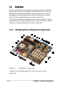
1.3.1 Identifying the motherboard components
Proceed to the succeeding pages for a brief description of each
component.
Figure 1-1 Motherboard Components
1
2
3
4
5
6
7
8
9
14
15
17
19
20
21
22
23
24
25
29
28
27
26
11
12
16
30
31
32
33
34
10
13
18

ASUS P4B-E motherboard user guide
1-3
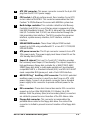
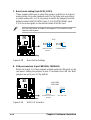
ATX 12V connector. This power connector connects the 4-pin 12V
plug from the ATX 12V power supply.
CPU socket. A 478-pin surface mount, Zero Insertion Force (ZIF)
socket called mPGA478 B. This socket accommodates the Intel
®
Pentium
®
4 478/Northwood Processor with 400MHz system bus.
North bridge controller. This controller called the Intel Memory
Controller Hub (MCH) is one of the two major components of the
Intel 845 (Brookdale) chipset. The MCH along with the south bridge
Intel I/O Controller Hub 2 (ICH2) are interconnected through the
Intel proprietary Hub interface. The MCH provides the processor
interface, system memory interface, AGP interface, and Hub
Interface.
SDRAM DIMM sockets. These three 168-pin DIMM sockets
support up to 3GB using unbuffered ECC or non-ECC PC100/133
SDRAM DIMMs.
ATX power connector. This 20-pin connector connects to an ATX
12V power supply. The power supply must have at least 1A on the
+5V standby lead (+5VSB).
Super I/O chipset. This Low Pin Count (LPC) interface provides
the commonly used Super I/O functionality. The chipset supports a
high-performance floppy disk controller for a 360K/720K/1.44M/
2.88M floppy disk drive, a multi-mode parallel port, two standard
compatible UARTs, a Standard Infrared (SIR), one MPU-401 UART
mode compatible MIDI/game port, and a Flash ROM interface.
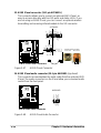
ASUS EZ Plug™ Auxilliary +12V connector. This ASUS patented
auxilliary power connector is used if you don’t have an ATX +12V
power supply. Connect a 4-pin device connector from a standard
power supply to this connector to provide sufficient power to the
CPU.
IDE connectors. These dual-channel bus master IDE connectors
support up to four Ultra DMA/100/66, PIO Modes 3 & 4 IDE
devices. Both the primary (blue) and secondary (black) connectors
are slotted to prevent incorrect insertion of the IDE ribbon cable.
Floppy disk connector. This connector accommodates the
provided ribbon cable for the floppy disk drive. One side of the
connector is slotted to prevent incorrect insertion of the floppy disk
cable.
1
2
3
4
5
7
6
8
9

1-4
Chapter 1: Product introduction
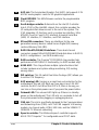
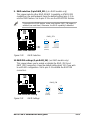
AGP slot. This Accelerated Graphics Port (AGP) slot supports 1.5V
AGP4X mode graphics cards for 3D graphical applications.
Flash EEPROM. This 4Mb firmware contains the programmable
BIOS program.
South bridge controller. Referred to as the Intel I/O Controller
Hub 2 (ICH2) of the Intel 845 chipset, this controller provides the
I/O subsystem that allows access to the rest of the system. The
ICH2 integrates I/O functions such as system bus interface, Ultra
ATA/100, Low Pin Count (LPC) interface, Universal Serial Bus
(USB) 1.1 interface, PCI interface, and CNR interface.
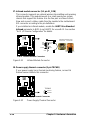
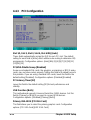
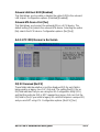
SD and MS connectors. These are interfaces for the new
generation memory devices called Secure Digital (SD) memory
card and Memory Stick (MS).
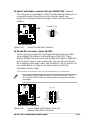
RAID Ultra ATA/100/66/33 interfaces. These dual-channel
connectors support Ultra ATA/100/66/33 hard disk drives in RAID 0/
RAID 1 configurations.
(on RAID models only)
RAID controller. This Promise
®
PDC20265R chip provides high
performance RAID 0/RAID 1 functionality.
(on RAID models only)
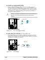
ASUS ASIC. This chip performs multiple system functions that
include hardware and system voltage monitoring, IRQ routing,
among others.
DIP switches. This 10-switch Dual Inline Package (DIP) allows you
to set the CPU frequency.
AGP warning LED. Serving as a smart burn-out protection for the
motherboard, this red LED lights up if you plug in any 3.3V AGP
card into the AGP slot. When this LED is lit, there is no way you
can turn on the system power even if you press the power button.
Onboard LED. This onboard LED lights up if there is a standby
power on the motherboard. This LED acts as a reminder to turn off
the system power before plugging or unplugging devices.
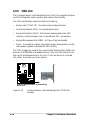
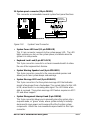
CNR slot. This slot is specifically designed for the Communications
and Networking Riser (CNR) card. The CNR supports V.90 analog
modem, six-channel audio, HPNA, USB Hub, and the 10BASE-T/
100BASE-TX Ethernet networking.
Speech controller. This Winbond speech controller supports
ASUS POST Reporter™ for configurable vocal POST alerts.
11
12
13
14
15
16
17
18
19
20
21
10

ASUS P4B-E motherboard user guide
1-5
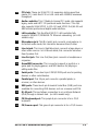
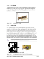
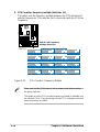
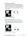
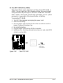
PCI slots. These six 32-bit PCI 2.2 expansion slots support bus
master PCI cards like SCSI or LAN cards with 133MB/s maximum
throughput.
Audio controller. This C-Media 6-channel PCI audio chip supports
legacy audio and HRTF 3D positional audio functions. The chip
also supports 24-bit SPDIF In (0.5~5V) and SPDIF Out (44.1K and
48K formats) professional digital audio interface.
LAN controller. This RealTek 8100 PCI LAN controller fully
supports 10BASE-T/100BASE-TX Ethernet networking.
(on LAN
models only)
Microphone jack. This Mic (pink) jack connects a microphone. In
6-channel audio mode, this connector becomes Bass/Center.
Line In jack. This Line In (light blue) jack connects a tape player or
other audio sources. In 6-channel mode, this connector becomes
Rear Speaker Out.
Line Out jack. This Line Out (lime) jack connects a headphone or
a speaker.
Game/MIDI connector. This connector supports a joystick or a
game pad for playing games, and MIDI devices for playing or
editing audio files.
Serial ports. These two 9-pin COM1/COM2 ports are for pointing
devices or other serial devices.
Parallel port. This 25-pin port connects a parallel printer, a
scanner, or other devices.
USB ports. These two 4-pin Universal Serial Bus (USB) ports are
available for connecting USB devices such as a mouse and PDA.
RJ-45 port. This port allows connection to a Local Area Network
(LAN) through a network hub.
(on LAN models only)
PS/2 keyboard port. This purple 6-pin connector is for a PS/2
keyboard.
PS/2 mouse port. This green 6-pin connector is for a PS/2 mouse.
22
23
24
25
26
27
28
29
30
31
32
33
34

1-6
Chapter 1: Product introduction
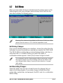
1.4 Special features
1.4.1 Product highlights
Latest processor technology
The P4B-E motherboard supports the latest Intel Pentium 4 478/
Northwood Processor, also known as P4, via a 478-pin surface mount ZIF
socket. The Pentium 4 processor utilizes the advanced 0.18 micron
processor core in FC-PGA2 package for a 2.0GHz frequency, while the
Northwood processor uses the 0.13 micron processor core with 512KB L2
cache for up to a speedy 2.4GHz frequency. The P4 offers optimized
performance for audio, video, and Internet applications.
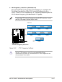
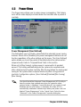
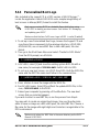
ASUS POST Reporter™
P4B-E offers a new exciting feature called the ASUS POST Reporter™ to
provide friendly voice messages and alerts during the Power-On Self-Tests
(POST). Through the system’s internal speaker, or an added external
speaker, you will hear the messages informing you of the system boot
status and causes of boot errors, if any. The bundled Winbond Voice
Editor software allows you to customize the voice messages, and provides
multi-language support.
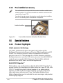
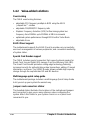
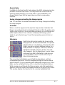
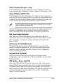
Figure 1-2 Pre-installed Heatsink Retention Module Base
This motherboard is shipped with the heatsink retention module base
already installed. This module should fit the retention mechanism that
comes with a boxed CPU.
You do not have to remove the retention module base when installing
the CPU or installing other motherboard components.
1.3.2 Pre-installed accessory
Retention Module Base

ASUS P4B-E motherboard user guide
1-7
ASUS EZ Plug™
This patented ASUS technology lets you use your existing power supply
rather than buying a new ATX 12V power supply. The ASUS EZ Plug™ is
a 4-pin auxillary +12V connector mounted on the motherboard that
connects a regular 4-pin device power connector from the power supply.
This connector is necessary to provide the additional power required by
the P4 CPU.
ASUS MyLogo™
This new feature present in the P4B-E motherboard allows you to
personalize and add style to your system using customizable boot logos.
Digital audio interface
On audio models, a digital audio connector is onboard to accommodate
the bundled Sony-Philips Digital Interface (SPDIF) In/Out module, which
supports coaxial and optical interfaces. Experience 5.1-channel surround
sound and enhanced 3D audio while playing your favorite DVDs and
computer games.
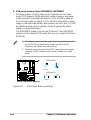
RAID 0/RAID 1 support
The motherboard includes the Promise
®
chip PDC20265R and two extra
Ultra ATA/100/66 interfaces to support Redundant Array of Independent
Disks (RAID) configuration. This feature requires UltraATA 100/66/33 hard
disks. The RAID chip onboard supports RAID 0 and RAID 1
configurations.
RAID 0 (called
data striping
) optimizes two identical hard disk drives to
read and write data in parallel, interleaved stacks. Two hard disks perform
the same work as a single drive but at a sustained data transfer rate,
double that of a single disk alone, thus improving data access and
storage. RAID 1 (called
data mirroring
) copies and maintains an identical
image of data from one drive to a second drive. If one drive fails, the disk
array management software directs all applications to the surviving drive
as it contains a complete copy of the data in the other drive. This RAID
configuration provides data protection and increases fault tolerance to the
entire system.

1-8
Chapter 1: Product introduction
1.4.2 Value-added solutions
Overclocking
The P4B-E overclocking features:
• adjustable CPU frequency multiple in BIOS using the ASUS
JumperFree™ solution
• adjsutable FSB/MEM/PCI frequency ratio
• Stepless Frequency Selection (SFS) for fine-tuning system bus
frequency from 100MHz up to 200MHz at 1MHz increments
• optimized system performance through BIOS built-in Turbo Mode
• adjustable Vcore
ASUS iPanel support
The motherboard supports the ASUS iPanel to provide easy connectivity,
one-touch management of various peripherals, and convenient monitoring
of system status.
Special Card Reader support
The P4B-E includes special connectors that support optional readers for
Smart Card, Secure Digital (SD) memory Card, and Memory Stick (MS).
The Smart Card Reader promotes cutting-edge technology featuring
increased security for authenticating online transactions, editing IC-based
information, and more. The SD/MS Reader allows portable high-capacity
storage through the sophisticated SD and MS devices.
Multi-language quick setup guide
The motherboard package includes a multi-language Quick Setup Guide
to let you set up your system the easiest way.
Jumpers and connectors sticker
This bundled sticker illustrates the locations of the motherboard jumpers
and connectors to give you an easy reference when configuring the
system. Attach this sticker to your system chassis or on a place most
convenient to you.
Page is loading ...
Page is loading ...
Page is loading ...
Page is loading ...
Page is loading ...
Page is loading ...
Page is loading ...
Page is loading ...
Page is loading ...
Page is loading ...
Page is loading ...
Page is loading ...
Page is loading ...
Page is loading ...
Page is loading ...
Page is loading ...
Page is loading ...
Page is loading ...
Page is loading ...
Page is loading ...
Page is loading ...
Page is loading ...
Page is loading ...
Page is loading ...
Page is loading ...
Page is loading ...
Page is loading ...
Page is loading ...
Page is loading ...
Page is loading ...
Page is loading ...
Page is loading ...
Page is loading ...
Page is loading ...
Page is loading ...
Page is loading ...
Page is loading ...
Page is loading ...
Page is loading ...
Page is loading ...
Page is loading ...
Page is loading ...
Page is loading ...
Page is loading ...
Page is loading ...
Page is loading ...
Page is loading ...
Page is loading ...
Page is loading ...
Page is loading ...
Page is loading ...
Page is loading ...
Page is loading ...
Page is loading ...
Page is loading ...
Page is loading ...
Page is loading ...
Page is loading ...
Page is loading ...
Page is loading ...
Page is loading ...
Page is loading ...
Page is loading ...
Page is loading ...
Page is loading ...
Page is loading ...
Page is loading ...
Page is loading ...
Page is loading ...
Page is loading ...
Page is loading ...
Page is loading ...
Page is loading ...
Page is loading ...
Page is loading ...
Page is loading ...
Page is loading ...
Page is loading ...
Page is loading ...
Page is loading ...
Page is loading ...
Page is loading ...
Page is loading ...
Page is loading ...
Page is loading ...
Page is loading ...
Page is loading ...
Page is loading ...
Page is loading ...
Page is loading ...
Page is loading ...
Page is loading ...
Page is loading ...
Page is loading ...
Page is loading ...
Page is loading ...
Page is loading ...
Page is loading ...
Page is loading ...
Page is loading ...
Page is loading ...
Page is loading ...
Page is loading ...
Page is loading ...
Page is loading ...
Page is loading ...
Page is loading ...
Page is loading ...
-
 1
1
-
 2
2
-
 3
3
-
 4
4
-
 5
5
-
 6
6
-
 7
7
-
 8
8
-
 9
9
-
 10
10
-
 11
11
-
 12
12
-
 13
13
-
 14
14
-
 15
15
-
 16
16
-
 17
17
-
 18
18
-
 19
19
-
 20
20
-
 21
21
-
 22
22
-
 23
23
-
 24
24
-
 25
25
-
 26
26
-
 27
27
-
 28
28
-
 29
29
-
 30
30
-
 31
31
-
 32
32
-
 33
33
-
 34
34
-
 35
35
-
 36
36
-
 37
37
-
 38
38
-
 39
39
-
 40
40
-
 41
41
-
 42
42
-
 43
43
-
 44
44
-
 45
45
-
 46
46
-
 47
47
-
 48
48
-
 49
49
-
 50
50
-
 51
51
-
 52
52
-
 53
53
-
 54
54
-
 55
55
-
 56
56
-
 57
57
-
 58
58
-
 59
59
-
 60
60
-
 61
61
-
 62
62
-
 63
63
-
 64
64
-
 65
65
-
 66
66
-
 67
67
-
 68
68
-
 69
69
-
 70
70
-
 71
71
-
 72
72
-
 73
73
-
 74
74
-
 75
75
-
 76
76
-
 77
77
-
 78
78
-
 79
79
-
 80
80
-
 81
81
-
 82
82
-
 83
83
-
 84
84
-
 85
85
-
 86
86
-
 87
87
-
 88
88
-
 89
89
-
 90
90
-
 91
91
-
 92
92
-
 93
93
-
 94
94
-
 95
95
-
 96
96
-
 97
97
-
 98
98
-
 99
99
-
 100
100
-
 101
101
-
 102
102
-
 103
103
-
 104
104
-
 105
105
-
 106
106
-
 107
107
-
 108
108
-
 109
109
-
 110
110
-
 111
111
-
 112
112
-
 113
113
-
 114
114
-
 115
115
-
 116
116
-
 117
117
-
 118
118
-
 119
119
-
 120
120
-
 121
121
-
 122
122
-
 123
123
-
 124
124
-
 125
125
-
 126
126
-
 127
127
-
 128
128


Asus P4B-E User manual
- Category
- Server/workstation motherboards
- Type
- User manual
Ask a question and I''ll find the answer in the document
Finding information in a document is now easier with AI
Related papers
Other documents
-
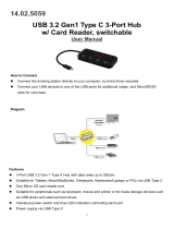 SECOMP 14.02.5059 USB 3.2 Gen1 Type C 3-Port Hub Card Reader Switchable User manual
-
 StarTech.com ATX2ATPOW Datasheet
-
Canyon CNR-MSO01O Datasheet
-
DeLOCK 91637 Datasheet
-
-
PC CHIPS P25G (V3.0) User guide
-
SOYO SY-P4IS2 User manual
-
-
BCM RX815ELT User manual
-
Belkin F3G523-02 Datasheet

