Page is loading ...

®
A7M266-D
Dual Socket A Motherboard
USER’S MANUAL

ASUS A7M266-D User’s Manual
2
USER'S NOTICE
Product Name: ASUS A7M266-D
Manual Revision: 1.02 E949
Release Date: January 2002
No part of this manual, including the products and software described in it, may be reproduced,
transmitted, transcribed, stored in a retrieval system, or translated into any language in any form
or by any means, except documentation kept by the purchaser for backup purposes, without the
express written permission of ASUSTeK COMPUTER INC. (“ASUS”).
ASUS PROVIDES THIS MANUAL “AS IS” WITHOUT WARRANTY OF ANY KIND, EI-
THER EXPRESS OR IMPLIED, INCLUDING BUT NOT LIMITED TO THE IMPLIED WAR-
RANTIES OR CONDITIONS OF MERCHANTABILITY OR FITNESS FOR A PARTICULAR
PURPOSE. IN NO EVENT SHALL ASUS, ITS DIRECTORS, OFFICERS, EMPLOYEES OR
AGENTS BE LIABLE FOR ANY INDIRECT, SPECIAL, INCIDENTAL, OR CONSEQUEN-
TIAL DAMAGES (INCLUDING DAMAGES FOR LOSS OF PROFITS, LOSS OF BUSINESS,
LOSS OF USE OR DATA, INTERRUPTION OF BUSINESS AND THE LIKE), EVEN IF ASUS
HAS BEEN ADVISED OF THE POSSIBILITY OF SUCH DAMAGES ARISING FROM ANY
DEFECT OR ERROR IN THIS MANUAL OR PRODUCT.
Product warranty or service will not be extended if: (1) the product is repaired, modified or al-
tered, unless such repair, modification of alteration is authorized in writing by ASUS; or (2) the
serial number of the product is defaced or missing.
Products and corporate names appearing in this manual may or may not be registered trademarks
or copyrights of their respective companies, and are used only for identification or explanation
and to the owners’ benefit, without intent to infringe.
• AMD, Athlon™ are trademarks of Advanced Micro Devices, Inc.
• VIA is a trademark of VIA Technologies, Inc.
• Windows and MS-DOS are registered trademarks of Microsoft Corporation.
• Adobe and Acrobat are registered trademarks of Adobe Systems Incorporated.
• Trend and ChipAwayVirus are trademarks of Trend Micro, Inc.
• Other company and product names may be trademarks or registered trademarks of the respective
companies with which they are associated.
The product name and revision number are both printed on the product itself. Manual revisions
are released for each product design represented by the digit before and after the period of the
manual revision number. Manual updates are represented by the third digit in the manual revision
number.
For previous or updated manuals, BIOS, drivers, or product release information, contact ASUS at
http://www.asus.com.tw or through any of the means indicated on the following page.
SPECIFICATIONS AND INFORMATION CONTAINED IN THIS MANUAL ARE FURNISHED
FOR INFORMATIONAL USE ONLY, AND ARE SUBJECT TO CHANGE AT ANY TIME WITH-
OUT NOTICE, AND SHOULD NOT BE CONSTRUED AS A COMMITMENT BY ASUS. ASUS
ASSUMES NO RESPONSIBILITY OR LIABILITY FOR ANY ERRORS OR INACCURA-
CIES THAT MAY APPEAR IN THIS MANUAL, INCLUDING THE PRODUCTS AND SOFT-
WARE DESCRIBED IN IT.
Copyright © 2002 ASUSTeK COMPUTER INC. All Rights Reserved.

ASUS A7M266-D User’s Manual 3
ASUS CONTACT INFORMATION
ASUSTeK COMPUTER INC. (Asia-Pacific)
Marketing
Address: 150 Li-Te Road, Peitou, Taipei, Taiwan 112
Telephone: +886-2-2894-3447
Fax: +886-2-2894-3449
Email: [email protected]
Technical Support
MB/Others (Tel): +886-2-2890-7121 (English)
Notebook (Tel): +886-2-2890-7122 (English)
Desktop/Server (Tel):+886-2-2890-7123 (English)
Fax: +886-2-2980-7698
Email: [email protected]
WWW: www.asus.com.tw
FTP: ftp.asus.com.tw/pub/ASUS
ASUS COMPUTER INTERNATIONAL (America)
Marketing
Address: 6737 Mowry Avenue, Mowry Business Center, Building 2
Newark, CA 94560, USA
Fax: +1-510-608-4555
Email: [email protected]
Technical Support
Fax: +1-510-608-4555
Email: [email protected]
WWW: www.asus.com
FTP: ftp.asus.com/Pub/ASUS
ASUS COMPUTER GmbH (Europe)
Marketing
Address: Harkortstr. 25, 40880 Ratingen, BRD, Germany
Fax: +49-2102-442066
Email: [email protected] (for marketing requests only)
Technical Support
Hotline: MB/Others: +49-2102-9599-0 Notebook: +49-2102-9599-10
Fax: +49-2102-9599-11
Support (Email): www.asuscom.de/de/support (for online support)
WWW: www.asuscom.de
FTP: ftp.asuscom.de/pub/ASUSCOM

ASUS A7M266-D User’s Manual
4
CONTENTS
1. INTRODUCTION 7
1.1 How This Manual Is Organized ................................................... 7
1.2 Item Checklist .............................................................................. 7
2. FEATURES 8
2.1 The ASUS A7M266-D ................................................................. 8
2.1.1 Core Specifications............................................................. 8
2.1.2 Connections ........................................................................ 9
2.1.3 Performance and Intelligence ........................................... 10
2.1.3 Intelligence ....................................................................... 11
2.2 Motherboard Components.......................................................... 12
2.2.1 Component Locations....................................................... 13
3. HARDWARE SETUP 14
3.1 Motherboard Layout .................................................................. 14
3.2 Layout Contents ......................................................................... 15
3.3 Getting Started ........................................................................... 16
3.4 Motherboard Settings ................................................................. 16
3.5 System Memory (DDR DIMM)................................................. 21
3.5.1 Memory Installation ......................................................... 22
3.5.2 General DIMM Memo...................................................... 22
3.6 Central Processing Unit (CPU) .................................................. 23
3.7 Expansion Cards ........................................................................ 24
3.7.1 Expansion Card Installation Procedure ............................ 24
3.7.2 Assigning IRQs for Expansion Cards .............................. 25
3.7.3 Accelerated Graphics Port Pro (AGP Pro) ....................... 26
3.7.4 ASUS
™
PCI-USB2 Card .................................................. 26
3.8 External Connectors ................................................................... 27
3.9 Starting Up the First Time.......................................................... 39
4. BIOS SETUP 41
4.1 Managing and Updating Your BIOS .......................................... 41
4.1.1 Upon First Use of the Computer System.......................... 41
4.1.2 Updating BIOS Procedures .............................................. 42
4.2 BIOS Setup Program.................................................................. 45
4.2.1 BIOS Menu Bar................................................................ 46
4.2.2 Legend Bar ....................................................................... 46
4.3 Main Menu ................................................................................. 48

ASUS A7M266-D User’s Manual 5
CONTENTS
4.3.1 Primary & Secondary Master/Slave ................................. 49
4.3.2 Keyboard Features............................................................ 52
4.4 Advanced Menu ......................................................................... 54
4.4.1 Chip Configuration........................................................... 57
4.4.2 I/O Device Configuration ................................................. 59
4.4.3 PCI Configuration ............................................................ 60
4.4.4 Shadow Configuration ...................................................... 64
4.5 Power Menu ............................................................................... 65
4.5.1 Power Up Control............................................................. 67
4.5.2 Hardware Monitor ............................................................ 69
4.6 Boot Menu ................................................................................. 70
4.7 Exit Menu................................................................................... 72
5. SOFTWARE SETUP 75
5.1 Install Operating System............................................................ 75
5.2 Start Windows ............................................................................ 75
5.3 A7M266-D Series Support CD .................................................. 75
6. SOFTWARE REFERENCE 77
6.1 ASUS PC Probe ......................................................................... 77
6.2 CyberLink PowerPlayer SE ....................................................... 83
6.3 CyberLink VideoLive Mail ........................................................ 83
6.4 ASUS Live Update..................................................................... 85
6.5 Multi-Channel Audio Feature Setup........................................... 86
6.6 3Deep Color Tuner..................................................................... 88
7. GLOSSARY 91
7.1 Qualified Vendors List ............................................................... 91
7.2 Glossary ..................................................................................... 93
INDEX ................................................................................................... 97

ASUS A7M266-D User’s Manual
6
FCC & DOC COMPLIANCE
Federal Communications Commission Statement
This device complies with FCC Rules Part 15. Operation is subject to the following
two conditions:
• This device may not cause harmful interference, and
• This device must accept any interference received, including interference that
may cause undesired operation.
This equipment has been tested and found to comply with the limits for a Class B
digital device, pursuant to Part 15 of the FCC Rules. These limits are designed to
provide reasonable protection against harmful interference in a residential installa-
tion. This equipment generates, uses and can radiate radio frequency energy and, if
not installed and used in accordance with manufacturer's instructions, may cause
harmful interference to radio communications. However, there is no guarantee that
interference will not occur in a particular installation. If this equipment does cause
harmful interference to radio or television reception, which can be determined by
turning the equipment off and on, the user is encouraged to try to correct the interfer-
ence by one or more of the following measures:
• Re-orient or relocate the receiving antenna.
• Increase the separation between the equipment and receiver.
• Connect the equipment to an outlet on a circuit different from that to which the
receiver is connected.
• Consult the dealer or an experienced radio/TV technician for help.
WARNING! Any changes or modifications to this product not expressly ap-
proved by the manufacturer could void any assurances of safety or performance
and could result in violation of Part 15 of the FCC Rules.
Reprinted from the Code of Federal Regulations #47, part 15.193, 1993. Washington DC: Office of the
Federal Register, National Archives and Records Administration, U.S. Government Printing Office.
Canadian Department of Communications Statement
This digital apparatus does not exceed the Class B limits for radio noise emissions
from digital apparatus set out in the Radio Interference Regulations of the Canadian
Department of Communications.
This Class B digital apparatus complies with Canadian ICES-003.
Cet appareil numérique de la classe B est conforme à la norme NMB-003 du Canada.

ASUS A7M266-D User’s Manual 7
1.1 How This Manual Is Organized
This manual is divided into the following sections:
1. INTRODUCTION Manual information and checklist
2. FEATURES Production information and specifications
3. HARDWARE SETUP Instructions on setting up the motherboard.
4. BIOS SETUP Instructions on setting up the BIOS
5. SOFTWARE SETUP Instructions on setting up the included software
6. SOFTWARE REFERENCE Reference material for the included software
7. APPENDIX Optional items and general reference
1.2 Item Checklist
Check that your package is complete. If you discover damaged or missing items,
contact your retailer.
1. INTRODUCTION
1. INTRODUCTION
Manual / Checklist
Package Contents
(1) ASUS Motherboard
(1) 40-pin 80-conductor ribbon
cable for internal UltraDMA/
100 / UltraDMA/66 (also
compatible with UltraDMA/33
IDE drives/devices)
(1) Ribbon cable for internal
UltraDMA/33 IDE drives
(1) Ribbon cable for one 5.25” and
two 3.5” floppy disk drives
(1) ASUS PCI-USB2 Card
(1) Bag of spare jumper caps
(1) ASUS Support CD with drivers
and utilities
(1) This Motherboard User’s
Manual
Optional Items
ASUS CIDB chassis intrusion detec-
tion module
ASUS IrDA-compliant infrared
module
ASUS iPanel
IMPORTANT NOTES!
1. This motherboard includes a four-port USB 2.0 card, the PCI-USB2, in
place of the conventional onboard USB 1.1 ports.
2. Entering BIOS setup with a USB keyboard is not possible, therefore, a
PS/2 keyboard is recommended with the A7M266-D motherboard.
3. Before setting up the system components, refer to Appendix 7.1 for a
Qualified Vendor’s list. All the components on the list have been tested and
are compatible with the A7M266-D motherboard.

8
ASUS A7M266-D User’s Manual
2.1 The ASUS A7M266-D
The ASUS A7M266-D motherboard is carefully designed for the value-conscious
PC user who needs an entry-level server with the most advanced features processed
by the fastest available processors.
2.1.1 Core Specifications
• Dual AMD Athlon
™
MP
Processor Support: Features the latest CPU, 1.6 GHz
and higher.
• North Bridge System Chipset: AMD-762
™
chipset with AGP / primary 64 bit
PCI / Memory controller supports a 266MHz/200MHz Front Side Bus (FSB),
supports DDR SDRAM DIMM, complies with AGP 2.0 specifications for 4X,
2X and 1X AGP modes and PCI 2.2. bus interface with support for two 66MHz
PCI masters. It is optimized to deliver enhanced performance with the new AMD
Athlon MP
™
.
• South Bridge System Chipset: AMD-768
™
PCI set with a secondary PCI bridge
using a 33MHz, 32-bit interface, PCI 2.2 compliant; PCI Super-I/O
Integrated Peripheral Controller (PSIPC) with support for UltraDMA/100, which
allows burst mode data transfer rates of up to 100MB/sec.
• PC2100 / PC1600 DDR SDRAM Support: Equipped with four Double Data
Rate Dual Inline Memory Module (DDR DIMM) sockets to support up to 3.5GB
of registered DDR SDRAM, or up to 2GB of unbuffered. DDR SDRAM sup-
plies the highest bandwidth and offers the lowest latency currently available,
improving the memory system’s ability to service multimedia requirements.
• UltraDMA/100 Support: Comes with an onboard PCI Bus Master IDE
controller with two connectors that support four IDE devices on two channels.
Supports UltraDMA/100 / 66 / 33, PIO Modes 3 & 4 and Bus Master IDE DMA
Mode 2, and Enhanced IDE devices, such as DVD-ROM, CD-ROM, CD-R/
RW, LS-120, and Tape Backup drives.
• Super Multi-I/O: The multi-I/O chipset offers complete support for a variety of
I/O functions. Provides two high-speed UART compatible serial ports and one
parallel port with EPP and ECP capabilities. UART2 can also be directed from
COM2 to the Infrared Module for wireless connections. The Super I/O
controller also supports a floppy disk drive, PS/2 keyboard, and PS/2 mouse.
• Smart BIOS: 2Mb firmware enables CPU/DDR SDRAM frequency
adjustments, boot block write protection, and HD/SCSI/MO/ZIP/CD/Floppy boot
selection.
2. FEATURES
Specifications
2. FEATURES

ASUS A7M266-D User’s Manual 9
2. FEATURES
2. FEATURES
Specifications
2.1.2 Connections
• Two CPU Sockets: Socket A (462) for dual AMD Athlon
™
MP
processors.
• PCI Expansion Slots: Provides five Legacy Free PCI slots: three PCI-32bit/
33MHz and two PCI-64bit/66MHz, (PCI 2.2 compliant. With no ISA, bottle-
necks and system memory management issues are eliminated. All PCI slots can
support Bus Master PCI cards, such as SCSI or LAN cards. (PCI supports up to
133MB/s maximum throughput.) The MB supports Concurrent PCI, which al-
lows multiple PCI transfers from PCI master bus to the memory and processor.
• IDE Connectors: Dual-channel bus master IDE connectors support up to four
Ultra DMA/100/66, PIO Modes 3 & 4 IDE devices like two HDDs, one DVD
and an R/W CD.
• AGP Pro Slot: Comes with an Accelerated Graphics Port Pro slot that
supports AGP cards for high performance, component level interconnect
targeted at 3D graphical applications using a 4X mode bus.
• Floppy Disk Connector: Supports the floppy disk drive.
• Serial Ports: Two 9-pin COM1/COM2 ports are for all serial devices.
• IrDA: Supports an optional infrared port module for a wireless interface.
• Parallel Port: 25-pin port connects a parallel printer or other devices.
• PS/2 mouse Port: Green 6-pin connector is for a PS/2 mouse.
• PS/2 keyboard Port: Purple 6-pin connector is for a PS/2 keyboard.
• Microphone jack: Pink jack connects a microphone. In 6-channel mode, the
function of this jack enables Bass/Center audio output.
• Line In jack: Light blue jack connects a tape player or other audio sources. In
6-channel mode, this jack enables rear speaker audio output.
• Line Out jack: Lime jack connects a headphone or speakers. In 6-channel
mode, this jack enables front speaker audio output.
• Three power Connectors: Standard ATX power supply: +5V/3.3V-180W; the
power supply must put out at least 1 Amp on the +5V standby lead (+5VSB);
ATX 12V/15 Amp power; and one auxillary power connector.

10
ASUS A7M266-D User’s Manual
2. FEATURES
Performance
2. FEATURES
2.1.3 Performance and Intelligence
• DDR SDRAM Optimized Performance: This motherboard supports Double Data
Rate (DDR) Dynamic Random Access Memory (DDR SDRAM). This new
memory technology increases performance by executing two actions per clock
cycle, resulting in data transfer rates of up to 2.1 GB/s for 266MHz DDR SDRAM
and 1.6 GB/s for 200MHz DDR SDRAM.
• Onboard Audio: Audio models come with the six-channel C-Media CMI8738
PCI audio controller that supplies HRTF 3D positional audio functions. A soft-
ware package helps setup the multi-channel PC sound system.
• ACPI Ready: Advanced Configuration Power Interface (ACPI) provides more
Energy Saving Features for operating systems that support OS Direct Power
Management (OSPM) functionality. With these features employed in the OS,
PCs can be ready around the clock but comply with energy saving standards. To
fully utilize the ACPI benefits, use an ACPI-supported OS such as Windows 98.
• Onboard LED: A green LED lights up to indicate that power is available on-
board. It reminds users that standby power is available. The LED also serves as
a reminder to disconnect the power supply when making any change to the
configuration.
• PCI USB2 Card: A 4-port USB PCI card is bundled with the A7M266-D.
• Concurrent PCI: Multiple PCI transfers are now harmonized from the PCI
master bus to the memory and processor.
• Remote Ring-On (requires modem): This allows a computer to be turned on
remotely through an internal or external modem. With this benefit on-hand, users
can access vital information from their computers anywhere.
• SMBus: Features the System Management Bus interface used to physically
transport commands and information between SMBus devices.
• Desktop Management Interface (DMI): Supports DMI through BIOS that al-
lows hardware to communicate within a standard protocol and create a higher
level of compatibility. (Requires DMI-enabled components.)
• ASUS C.O.P. (CPU Overheating Protection): With AMD
®
Athlon XP
™
/ Athlon MP
™
installed, the motherboard offers users ASUS C.O.P. automatic
CPU Overheating Protection to prolong the life of the entire system. If the CPU
temperature becomes excessive, the PC shuts down automatically.
• Auto Fan Off: The system fans powers off automatically even in sleep mode.
This function reduces both energy consumption and system noise, and is an
important feature in implementing silent PC systems. Note: the user must change
the default setting in BIOS to take advantage of this feature.

ASUS A7M266-D User’s Manual 11
2. FEATURES
2. FEATURES
Intelligence
• Enhanced ACPI and Anti-Boot Virus Protection: Programmable BIOS (Flash
EEPROM) that offers enhanced ACPI for Windows 98/2000/ME/XP compat-
ibility, built-in firmware-based virus protection, and autodetection of most de-
vices for a virtual automatic setup.
• Chassis Intrusion Detection: Supports chassis-intrusion monitoring through
the ASUS ASIC. A chassis intrusion event is kept in memory on battery power
for more protection.
• Easy Connectivity and System Information Access: Supports an optional
ASUS iPanel, an easy-to-access box with system diagnostic display area, sys-
tem status LEDs, USB ports, and hot keys. The AFPANEL connector on the
motherboard accommodates the ASUS iPanel.
• PC Health Monitoring: Provides an easy way to test and manage system status
information, such as CPU and system voltages, temperatures, and fan status
through the onboard hardware ASUS ASIC and the bundled ASUS PC Probe.
• Dual Function Power Button: Pushing the power button for less than 4 sec-
onds when the system is in the working state places the system into one of two
states: sleep mode or soft-off mode, depending on the BIOS or OS setting (See
PWR Button < 4 Secs in 4.5 Power Menu). When the power button is pressed
for more than 4 seconds, the system enters the soft-off mode regardless of the
BIOS setting.

12
ASUS A7M266-D User’s Manual
2. FEATURES
2. FEATURES
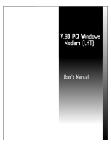
Motherboard Parts
Location
Processor Support Dual Socket A (462) for AMD Athlon MP
™
...................................................
4
DSW switches .......................................................................... 8
Chipsets AMD 762 System Controller .................................................... 5
AMD 768 PCI Set .................................................................. 11
2Mbit Programmable Flash EEPROM ................................... 14
LPC Multi-IO Controller Chipset........................................... 15
Main Memory Maximum 4GB Support
4 DIMM Sockets ...................................................................... 6
PC2100 DDR memory support
Expansion Slots 2 64/32bit 66/33MHz PCI Slots ............................................. 18
3 32bit 33MHz PCI Slots ....................................................... 12
1 Accelerated Graphics Port (AGP) Pro Slot ......................... 19
System I/O 1 Floppy Disk Drive Connector ............................................... 7
2 IDE Connectors (UltraDMA/100 Support) ......................... 10
1 Front Audio Panel Connector .............................................. 13
1 Parallel Port Connector ............................................. (Top) 24
1 Serial COM1 Port Connector .............................. (Bottom) 25
1 Serial COM2 Port Connector .............................. (Bottom) 23
1 PS/2 Mouse Connector .............................................. (Top) 26
1 PS/2 Keyboard Connector ................................... (Bottom) 26
Audio PCI 6-Channel Audio Controller (optional) ........................... 17
1 Line Out Connector (audio model only)..................(Lime) 22
1 Line In Connector (audio model only) ........... (Light blue) 21
1 Microphone Connector (audio model only) ............(Pink) 20
Hardware Monitoring ASUS ASIC .............................................................................. 9
Power Auxillary Power Connector ...................................................... 1
12V ATX Power Supply Connector ......................................... 2
ATX Power Supply Connector ................................................. 3
Special Feature Onboard LED ......................................................................... 16
Form Factor AT X
2.2 Motherboard Components
See opposite page for locations.

ASUS A7M266-D User’s Manual 13
2. FEATURES
2. FEATURES
Motherboard Parts
2
25
6
19
24
17
3 4
9
18
5
23
1
87
101112
14
15
21
26
13
20
22
16
2.2.1 Component Locations

14
ASUS A7M266-D User’s Manual
3. HARDWARE SETUP
3.1 Motherboard Layout
Motherboard Layout
3. H/W SETUP
Grayed components are available only on certain models at the time of purchase.
24.5cm (9.6in)
30.5cm (12in)
COM1
COM2
PARALLEL PORT
LED1
CPU1_FAN
CHA_FAN
Accelerated Graphic Port (AGP PRO)
PCI Slot 1
PANEL
FLOPPY
SECONDARY IDE
ATX Power Connector
IR_CON
DDR DIMM1 (64/72 bit, 184-pin module)
0 1
A7M266-D
SMB
PRIMARY IDE
®
PS/2
T: Mouse
B: Keyboard
JEN
AMD762
System
Controller
ASUS
ASIC
with Hardware
Monitor
AFPANEL
CHASSIS
IDELED
CD
AUX
C-Media
CMI-8738
PCI Audio
MODEM
Socket 462
Socket 462
DDR DIMM2 (64/72 bit, 184-pin module)
2 3
DDR DIMM3 (64/72 bit, 184-pin module)
4 5
DDR DIMM4 (64/72 bit, 184-pin module)
6 7
AUX Power
Connector
ATX12V
CPU0_FAN
PWR_FAN
CR2032 3V
Lithium Cell
CMOS Power
DSW
CLRTC
PCI Slot 2
PCI Slot 3
PCI Slot 4
PCI Slot 5
BCS1
BCS2
HPHONE
AAPANEL
P0_VID1
P0_VID2
P0_VID3
P0_VID4
AMD-768
Chipset
2Mbit
Firmware
Hub
Multi
I/O
MIC2
LINE_IN
2.5V
Line
Oit
Line
In
Mic
In
CPU0
CPU1

ASUS A7M266-D User’s Manual 15
3. HARDWARE SETUP
3.2 Layout Contents
Motherboard Settings
1) JEN p. 17 Jumper Mode (JumperFree / Jumper Mode)
2) VDDR p. 18 DDR Memory Voltage Setting (2.5 / 2.6 / 2.7)
3) BCS1/2 p. 18 Bass Center Setting (CENTER/BASS, BASS/CENTER)
4) DSW 1–4 p. 19 CPU External Frequency Setting (Switches 1–4)
6) PO_VID1-4 p. 20 CPUO Voltage Regulator Output Setting
Expansion Slots / Sockets / Cards
1) DDR System Memory p. 21 System Memory Support
2) DIMM1/2/3/4 p. 22 DDR DIMM Memory Installation
3) Socket 462 (Socket A) p. 23 CPU Support
4) PCI1/2/3/4/5 p. 24 Two 64-bit and three 32-bit PCI Bus Expansion Slots
5) AGP PRO p. 26 Accelerated Graphics Port (AGP) Pro
6) PCI-USB2 p. 26 ASUS USB PCI Card
Connectors
1) PS2KBMS p. 27 PS/2 Mouse Porv Connector (6 pin female)
2) PS2KBMS p. 27 PS/2 Keyboard Port Connector (6 pin female)
3) COM1/COM2 p. 28 Serial Port Connector (9 pin male)
4) PRINTER p. 28 Parallel Port Connector (25 pin female)
5) Line_In, Line_Out, Mic p. 29 Audio Port Connectors (Three 1/8”) (optional)
6) FLOPPY p. 29 Floppy Disk Drive Connector (34 pins)
7) PRIM. / SECOND. IDE p. 30 IDE Connectors (Two 40-1 pins)
8) CHASSIS p. 31 Chassis Intrusion Lead (4-1 pins)
9) IR_CON p. 31 Infrared Module Connector (5 pins)
10)
CHA, PWR, CPU0, CPU1_FAN
p. 32 Chassis, Power Supply, CPU0 & 1 Fan Connectors (3 pins)
11) SMB p. 33 SMBus Connector (5-1 pins)
12) MIC2 p. 33 Internal Microphone Connector (3-pin)
13) AFPANEL p. 34 ASUS iPanel Connector (24-1 pins)
14) HPHONE p. 35 Headphone True-level Line Out Header (3-pin)
15) LINE_IN p. 35 Audio Input Line In Header (5-pin) (optional)
16) IAPANEL p. 36 ASUS iPanel Audio Connector (10-1 pin) (optional)
17) IDELED p. 36 IDE Activity LED (2 pins)
18) ATXPWR p. 37 ATX Power Supply Connectors (20 pin block ATXPWR,
12 pin EAUXPWER, 4 pin ATX12V)
19) PWRLED (PANEL) p. 38 System Power LED Lead (3 pins)
20) KEYLOCK (PANEL) p. 38 Keylock Switch Lead (2 pins)
21) SPEAKER (PANEL) p. 38 System Warning Speaker Connector (4 pins)
22) MSGLED (PANEL) p. 38 System Message LED (2 pins)
23) SMISW (PANEL) p. 38 System Management Interrupt Lead (2 pins)
24) PWRSW (PANEL) p. 38 ATX / Soft-Off Switch Lead (2 pins)
25) RESET (PANEL) p. 38 Reset Switch Lead (2 pins)
Layout Contents
3. H/W SETUP

16
ASUS A7M266-D User’s Manual
3. HARDWARE SETUP
Layout Contents
3. H/W SETUP
3.3 Getting Started
Before using your computer, you must complete the following steps:
1. Check Motherboard Settings
2. Install Memory Modules
3. Install the Central Processing Unit (CPU)
4. Install Expansion Cards
5. Connect Ribbon Cables, Panel Wires, and Power Supply
6. Setup the BIOS Software
3.4 Motherboard Settings
This section explains in detail how to change your motherboard’s function settings
through the use of switches and/or jumpers.
A7M266-D
®
A7M266-D Onboard LED
ON
OFF
Standby
Power
Powered
Off
WARNING! Computer motherboards and expansion cards contain very delicate
Integrated Circuit (IC) chips. To protect them against damage from static electric-
ity, you should follow some precautions whenever you work on your computer.
1. Unplug your computer when working on the inside.
2. Use a grounded wrist strap before handling computer components. If you do
not have one, touch both of your hands to a safely grounded object or to a
metal object, such as the power supply case.
3. Hold components by the edges and try not to touch the IC chips, leads or
connectors, or other components.
4. Place components on a grounded antistatic pad or on the bag that came with
the component whenever the components are separated from the system.
5. Ensure that the ATX power supply is switched off before you plug in or
remove the ATX power connector on the motherboard.
WARNING! Make sure that you unplug your power supply when adding or
removing system components. Failure to do so may cause severe damage to your
motherboard, peripherals, and/or components. The onboard LED when lit acts as
a reminder that the system is in suspend or soft-off mode and not powered OFF.

ASUS A7M266-D User’s Manual 17
3. HARDWARE SETUP
3. H/W SETUP
Motherboard Settings
Motherboard Features Settings (DIP Switches - DSW)
The motherboard’s onboard functions are adjusted through the DIP switches. The
white block represents the switch’s position. The example below shows all the
switches in the OFF position.
A7M266-D
®
Frequency Selection
DSW
OFF
ON
12
34
A7M266-D DIP Switch
ON
133MHz
(Default)
1) Jumper Mode / JumperFree
™
Mode (JEN)
This motherboard FSB is preset to operate at 133MHz in Jumper Mode, [1-2].
Changing the jumper to [2-3] enables JumperFree™ mode, which permits
processor settings through BIOS setup (see 4.4 Advanced Menu).
A7M266-D
®
A7M266-D Jumper Mode Setting
Jumper FreeJumper Mode
12
2
3
(Default)
JEN

18
ASUS A7M266-D User’s Manual
3. HARDWARE SETUP
2) DDR Voltage Setting (VDDR)
This jumper controls the voltage output to the DDR memory DRAMS. Less
strain is placed on components at lower voltage settings.
Setting VDDR (2.5V)
2.5V [1-2]
2.6V [2-3] (default)
2.7V [3-4]
3. H/W SETUP
Motherboard Settings
A7M266-D
®
A7M266-D 2.5V Setting
2
1
2.5V
4
3
2.7V
2.5V
3
2
(Default)
2.6V
A7M266-D
®
A7M266-D Bass Center Setting
(CENTER/BASS)(BASS/CENTER)
(default)
1
2
BCS1
BCS2
2
3
BCS1
BCS2
3) Bass Center Setting (CENTER/BASS, BASS/CENTER)
Use these jumpers in conjunction with the C-Media PCI Audio Driver and to
adjust output for 6 speaker audio. No audio standard exists for the three pick-up
surfaces on male audio jacks, therefore it may be necessary to switch jumpers
from the default position, [2-3] to [1-2] in order to reroute signals among the
internal leads in the Line-In, Line-Out, Mic female sockets. Make sure a test is
made using the C-Media Audio Driver software setup available on the Support
CD.

ASUS A7M266-D User’s Manual 19
3. HARDWARE SETUP
3. H/W SETUP
Motherboard Settings
4) CPU External Frequency Setting (DSW Switches 1–4)
This option tells the clock generator what frequency to send to the CPU, SDRAM,
and the chipset. This allows the selection of the CPU’s External frequency. The
CPU External Frequency multiplied by the Frequency Multiple equals the CPU’s
Internal frequency (the advertised CPU speed).
IMPORTANT:
1. To use this feature, check the JEN jumper settings: see Jumper/
JumperFree™ Mode (JEN) on the previous pages.
A7M266-D
®
A7M266-D CPU External Frequency Selection
DSW
CPU 100MHz 103MHz
110MHz 115MHz
ON
12
34
CPU
ON
12
34
ON
12
34
ON
12
34
ON
12
34
ON
12
34
105MHz
133MHz
Frequency Table
(MHz) DSW
CPU 1 2 3 4
100 [ON] [OFF] [ON] [ON]
103 [OFF] [ON] [OFF] [ON]
105 [ON] [OFF] [OFF] [ON]
110 [OFF] [OFF] [OFF] [ON]
115 [OFF] [OFF] [ON] [ON]
133 [ON] [ON] [ON] [OFF]
WARNING! Frequencies other than the recommended CPU bus frequencies are
not guaranteed to be stable. Overclocking your processor is not recommended. It
may result in a slower speed and premature wearing of the processor.

20
ASUS A7M266-D User’s Manual
3. HARDWARE SETUP
3. H/W SETUP
Motherboard Settings
5) Voltage Regulator Output Setting (PO_VID1 - 4)
This jumpers allow you to manually adjust the CPUO core voltage. It is
recommended to use CPU Default (all jumpers [3-4]) as the setting for CPU
core voltage. CPU Default means that the Vcore is generated according to the
CPU-VID design configuration. For each jumper setting, there are two voltage
options, depending on the CPU used. NOTE: After PCB 1.04, the PO_VID
jumpers simultaneously adjust voltages for both CPU0 and CPU1.
A7M266-D
®
A7M266-D CPU0 Core Voltage
Selection
1.35/1.325Volts
1.30/1.275Volts
1.20/1.175Volts
1.10/1.075Volts
CPU Default/
JumperMode
(Default)
1.40/1.375Volts
1.15/1.125Volts
1.25/1.225Volts
3214 3214 3214
1.8/1.775Volts 1.75/1.725Volts
1.65/1.625Volts
1.55/1.525Volts 1.50/1.475Volts
1.85/1.825Volts
1.6/1.575Volts
1.7/1.675Volts
1.45/1.425Volts
PO_VID2
PO_VID3
PO_VID1
PO_VID4
PO_VID2
PO_VID3
PO_VID1
PO_VID4
PO_VID2
PO_VID3
PO_VID1
PO_VID4
PO_VID2
PO_VID3
PO_VID1
PO_VID4
PO_VID2
PO_VID3
PO_VID1
PO_VID4
PO_VID2
PO_VID3
PO_VID1
PO_VID4
/