Page is loading ...

SY-P4IS2
Motherboard
****************************************************
mPGA Socket 478 Processor supported
Intel i845 AGP/PCI/CNR
400 MHz Front Side Bus supported
ATX Form Factor
****************************************************
User's Manual

SOYO ™ SY-P4IS2
ii
Copyright © 2001 by Soyo Computer Inc.
Trademarks:
Soyo is the registered trademark of Soyo Computer Inc. All trademarks are the
properties of their owners.
Product Rights:
All names of the product and corporate mentioned in this publication are used for
identification purposes only. The registered trademarks and copyrights belong to
their respective companies.
Copyright Notice:
All rights reserved. This manual has been copyrighted by Soyo Computer Inc. No
part of this manual may be reproduced, transmitted, transcribed, translated into any
other language, or stored in a retrieval system, in any form or by any means, such
as by electronic, mechanical, magnetic, optical, chemical, manual or otherwise,
without permission in writing from Soyo Computer Inc.
Disclaimer:
Soyo Computer Inc. makes no representations or warranties regarding the contents
of this manual. We reserve the right to amend the manual or revise the
specifications of the product described in it from time to time without obligation to
notify any person of such revision or amend. The information contained in this
manual is provided to our customers for general use. Customers should be aware
that the personal computer field is subject to many patents. All of our customers
should ensure that their use of our products does not infringe upon any patents. It is
the policy of Soyo Computer Inc. to respect the valid patent rights of third parties
and not to infringe upon or to cause others to infringe upon such rights.
Restricted Rights Legend:
Use, duplication, or disclosure by the Government is subject to restrictions set
forth in subparagraph (c)(1)(ii) of the Rights in Technical Data and Computer
Software clause at 252.277-7013.
About This Guide:
This Quick Start Guide can help system manufacturers and end users in setting up
and installing the Motherboard. Information in this guide has been carefully
checked for reliability; however, to the correctness of the contents there is no
guarantee given. The information in this document is subject to amend without
notice.
For further information, please visit our Web Site on the Internet. The address is
"http://www.soyo.com.tw".
Edition: July 2001
Version 1.0
P4IS2 SERIAL
FC
C
Tested To Comply
With FCC Standards
FOR HOME OR OFFICE USE
POST CONSUMER
RECYCLED PAPER100%

Table of Contents SY-P4IS2
iii
Table of Contents
CHAPTER 1 MOTHERBOARD DESCRIPTION....................................1
1-1 INTRODUCTION......................................................................1
1-2 HANDLING THE MOTHERBOARD...................................3
1-3 ELECTROSTATIC DISCHARGE PRECAUTIONS...........3
1-4 SY-P4IS2 MOTHERBOARD LAYOUT .........................................4
1-5 SY-P4IS2 MOTHERBOARD COMPONENTS...............................5
1-6 CHIPSET.........................................................................................7
1-7 I/O INTERFACE CONTROLLER..................................................13
1-8 WAKE ON LAN TECHNOLOGY.................................................16
CHAPTER 2 HARDWARE INSTALLATION .........................................18
2-1 PREPARATIONS...........................................................................18
2-2 UNPACKING THE MOTHERBOARD...........................................19
2-3 INSTALLATION GUIDE................................................................20
2-3.1 CPU Installation............................................................21
2-3.2 SDRAM Memory Module Installation......................24
2-3.3 Motherboard Connector ...............................................25
2-3.4 Jumper Setting................................................................41
2-3.5 Power On.........................................................................42
2-3.6 Quick BIOS Setup..........................................................43
2-3.7 Troubleshooting at First Start......................................44
2-3.8 Power Off........................................................................48
CHAPTER 3 BIOS SETUP UTILITY........................................................49
3-1 SOYO COMBO SETUP.........................................................52
3-2 STANDARD CMOS SETUP.................................................56
3-3 ADVANCED BIOS FEATURES...................................................59
3-4 ADVANCED CHIPSET FEATURES...............................................64
3-5 INTEGRATED PERIPHERALS ...........................................66
3-6 POWER MANAGEMENT SETUP ......................................71

Table of Contents SY-P4IS2
iv
3-7 PNP/PCI CONFIGURATION SETUP.................................75
3-8 PC HEALTH STATUS..................................................................78
3-9 LOAD FAIL-SAFE DEFAULTS...............................................80
3-10 LOAD OPTIMIZED DEFAULTS..............................................81
3-11 SUPERVISOR PASSWORD..................................................82
3-12 USER PASSWORD.................................................................83
CHAPTER 4 DRIVERS INSTALLATION................................................85

Motherboard Description SY-P4IS2
1
Chapter 1
MOTHEBOARD DESCRIPTION
1-1 INTRODUCTION
Ø The SY-P4IS2 AGP/PCI/CNR Motherboard is a high-performance
Socket 478 processor supported ATX form-factor system board.
SY-P4IS2 uses the Intel i845 Chipset technology. This Motherboard
is fully compatible with industry standards
Supports Intel® mPGA Socket 478 processors
- FSB 400MHz: Pentium® 4
Ø Supports 400 MHz Front Side Bus Frequency
Ø PC99, ACPI
Ø Ultra DMA33/66/100 (ATA 33/66/100)
Ø Supports Wake-On-LAN (WOL)
Ø Supports PC-133 Unbuffer SDRAM and ECC
Ø Supports ACPI Suspend Indicator
Ø Power-on by modem, alarm and PS/2 Keyboard
Ø Power failure resume
Ø Supports Suspend to RAM
Ø Supports onboard hardware monitoring and includes Hardware
Doctor™ utility
Ø Supports AC97 Codec
Ø Easy CPU settings in BIOS with the “SOYO COMBO Setup”
- CPU voltage adjust
- CPU ratio adjust
- CPU FSB adjust
Ø Supports multiple-boot function
Ø AGP 2.0 Compliant;

Motherboard Description SY-P4IS2
2
AGP Connector supports:
- 1.5V only AGP card
- 2X/4X data transfer
Ø Supports Communication Networking Riser Slot (CNR 1.0
compliant) *
Ø Smart Card Reader
- Compliant with Personal Computer Smart Card (PC/SC) Working
Group standard
- Compliant with smart card (ISO 7816) protocols
- Supports card present detect
- Supports Smart Card insertion power-on feature
Ø 3 x DIMM slots for SDRAM memory
Ø 1 x 32-bit AGP slot
Ø 6 x 32-bit bus master PCI slots
Ø 4 x USB ports onboard
Ø 1 x IrDA port
Ø ATX 12V power connector
Warning: This M/B can only support 1.5V AGP card.

Motherboard Description SY-P4IS2
3
1-2 HANDLING THE MOTHERBOARD
To avoid damage to your Motherboard, follow these simple rules while
unpacking:
Ø Before handling the Motherboard, ground yourself by grasping an
unpainted portion of the system's metal chassis.
Ø Remove the Motherboard from its anti-static packaging. Hold the
Motherboard by the edges and avoid touching its components.
Ø Check the Motherboard for damage. If any chip appears loose, press
carefully to seat it firmly in its socket.
Warning: Do not apply power if the Motherboard appears
damaged. If there is damage to the board, contact your dealer
immediately.
1-3 ELECTROSTATIC DISCHARGE PRECAUTIONS
Make sure to ground yourself before handling the Motherboard or other
system components. Electrostatic discharge can easily damage the
components. Note that you must take special precautions when handling
the Motherboard in dry or air-conditioned environment.
To protect your equipment from electrostatic discharge, take the following
precautions:
Ø Do not remove the anti-static packaging until you are ready to install.
Ø Ground yourself before removing any system component from its
protective anti-static packaging. (To ground yourself, grasp the expansion
slot covers or other unpainted portions of the computer chassis.)
Ø Frequently ground yourself while working or use a grounding strap.
Ø Handle the Motherboard by its edges and avoid touching its
components.

Motherboard Description SY-P4IS2
4
1-4 SY-P4IS2 MOTHERBOARD LAYOUT
Back Panel SY-P4IS2 Platform
USB 1 USB 2
PS/2 KB
Connector
PS/2 MousePS/2 Mouse
Connector
3V
Lithium
Battery
IDE 1IDE 2
ATX Power
PCI#6
PCI#5
PCI#4
PCI#3
PCI#1
PCI#2
PRT
COM A
COM B
CNR1
SYSFAN
ITE
IT8712F-A
DIM M1
DIM M2
DIM M3
13
2
1
SMCARDCN
14
JP4
12
SIRCON
1
6
5
10
USB3_4
1
210
9
FDC1
WOL
Header
JP10
CMOS Clear
Jumper
1
JP5
CDIN
1 4
AOUT
AIN
AMIC
AGAME
Sigmatel
STAC 9700
SW1
Power
LED
Keylock
Speaker
ACPI
LED
HDD
LED
PWRBT
Reset
J25
P1
P2
AGP Slot

Motherboard Description SY-P4IS2
5
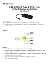
1-5 SY-P4IS2 MOTHERBOARD COMPONENTS
A
B
C
D
E
F
G
H
I
J
K
L
M
N
O
P
Q
R
S
T
U
V
W
X
Y
Z
AA
AB
AC

Motherboard Description SY-P4IS2
6
A ATX12V 4-Pin(+12V) Connector
B ATX12V 6-Pin(+3.3V, +5V) Connector
C Socket 478 Connector
D Intel i845 North Bridge Chip
E CPU Cooling Fan Connector
F DIMM Bank
G ATX Power Connector
H Floppy Disk Drive (FDD)
I Bus Mastering E-IDE/ATAPI Ports
J CMOS Clear Jumper
K Intel FW82801BA South Bridge Chip
L Chassis Cooling Fan Connector
M Front panel connectors
N 3V Lithium Battery
O Flash BIOS
P USB Connector
Q System Fan Connector
R Serial Infrared (IrDA) Device Header
S Smart Card Reader Connector
T CNR MR Card-CODEC OPTION Setting Jumper
U Communication Networking Riser Slot
V ITE I/O Chip
W 32-bit PCI Mastering Slots
X On Board Codec Enabled/Disabled Setting Switch
Y Wake-On-LAN(WOL) Header
Z CD-IN Connectors
AA AC97 Codec Chip
AB 32-bit AGP slot
AC Back panel Conectors

Motherboard Description SY-P4IS2
7
1-6 CHIPSET
The Intel® 845 chipset Memory Controller Hub (MCH) is designed
for use with the Intel® Pentium 4 processor and Northwood
processor in the 478-pin package. The Intel ® 845 chipset MCH role
in a system is to manage the flow of information between its four
interfaces: the System Bus, the memory interface, the AGP port, and
the Hub Interface. The MCH arbitrates between the four interfaces,
when each initiates an operation. While doing so, the MCH must
support data coherency via snooping and must perform address
translation for access to AGP Aperture memory. To increase system
performance, the MCH incorporates several queues, and a write
cache.
The Intel® 845 chipset Memory Controller Hub (MCH) may contain
design defects or errors known as errata which may cause the
product to deviate from published specifications.
1-6.1 System Architecture
The Intel® 845 chipset Memory Controller Hub (MCH) component
provides the processor interface, DRAM interface, AGP interface,
and Hub Interface in an Intel® 845 chipset desktop platform. The
processor interface supports the Intel® Pentium 4 processor subset
of the Extended Mode of the Scalable Bus Protocol. Intel® 845
chipset is optimized for the Intel® Pentium 4 processor and
Northwood processor. It supports a single channel of PC133
SDRAM. The MCH contains advanced power management logic.
The Intel® 845 chipset platform supports the second generation I/O
Controller Hub (Intel ICH2) to provide the features required by a
desktop platform.
The Intel® 845 chipset MCH is in a 593-pin FC-BGA package and
contains the following functionality:
l Supports single Intel® Pentium 4 processor/Northwood
processor configurations at 400MHz

Motherboard Description SY-P4IS2
8
l AGTL+ system bus with integrated termination supporting
32-bit system bus addressing
l Up to 3GB (w/ 512-Mb technology) of PC133 SDRAM
l 1.5V AGP interface with 4x SBA/Data Transfer and 2x/4x
Fast Write capability
l 8 bit, 66 MHz 4x Hub Interface to Intel ICH2
l Distributed arbitration for highly concurrent operation
1-6.2 Intel® Pentium® 4 Processor/Northwood Processor
System Bus Interface
The Intel® 845 chipset MCH is optimized for the Intel® Pentium 4
processor/Northwood processor in the 478-pin package. The primary
enhancements over the Compatible Mode P6 bus protocol are:
l Source synchronous double pumped address
l Source synchronous quad pumped data
l System bus interrupt and side-band signal delivery
In this mode, the MCH supports a 64B cache line size. Only one
processor is supported at a System bus frequency of 400 MHz. The
MCH supports a 3:4 Host-to-Memory frequency ratio (using the 100
MHz clock). The MCH integrates AGTL+ termination resistors on
all of the AGTL+ signals. The MCH supports 32-bit system bus
addresses, allowing the processor to access the entire 4GB of the
MCH memory address space.
The MCH has a 12-deep In-Order Queue to support up to twelve
outstanding pipelined address requests on the system bus. The MCH
supports two outstanding defer cycles at a time, however only one to
any particular IO interface. Processor initiated I/O cycles are
positively decoded to AGP/PCI or MCH configuration space and
subtractively decoded to the Hub Interface. Processor initiated
memory cycles are positively decoded to AGP/PCI or DRAM, and
are again subtractively decoded to the Hub Interface if under 4GB.
AGP semantic memory accesses initiated from AGP/PCI to DRAM
are not snooped on the system bus. Memory accesses initiated from

Motherboard Description SY-P4IS2
9
AGP/PCI using PCI semantics and from the Hub Interface to Dram
will be snooped on the system bus. Memory accesses whose
addresses lie within the AGP aperture are translated using the AGP
address translation table, regardless of the originating interface.
1-6.3 DRAM Interface
The Intel® 845 chipset memory controller directly supports one
channel of PC133 SDRAM memory. The Intel® 845 chipset
memory interface supports SDR SDRAM devices with densities of
64-Mb, 128-Mb, 256-Mb, and 512-Mb technoloty. The Intel® 845
chipset memory interface also supports variable page sized of 2KB,
4KB, 8KB, and 16KB. Page size is individually selected for every
row and a maximum of 8 pages per DIMM may be opened
simultaneously.
Technology
SDR (PC133) Maximum
64 Mb 384 MB
128 Mb 768 MB
256 Mb 1.5 GB
512 Mb 3 GB
The memory interface provides optional ECC error checking for
DRAM data integrity. During DRAM writes, ECC is generated on a
QWORD (64bit) basis. Because the Intel® 845 chipset MCH stores
only entire cache lines in its internal buffers, partial QWORD writes
initially cause a read of the underlying data, and their write-back
into memory is no different from that of a complete cache line.
During DRAM reads, and the read of the data that underlies partial
writes, the MCH supports detection of single-bit and multiple-bit
errors, and will correct single bit errors when correction is enabled.
1-6.4 AGP Interface
A single AGP component or connector (not both) is supported by the
Intel® 845 chipset MCH AGP interface. The AGP buffers operate
only in 1.5V mode. They are not 3.3V safe.
The AGP interface supports 2x/4x AGP signaling and 2x/4x Fast

Motherboard Description SY-P4IS2
10
Writes. AGP semantic cycles to DRAM are not snooped on the
system bus. PCI semantic cycles to DRAM are snooped on the
system bus. The MCH supports PIPE# or SBA[7:0] AGP address
mechanisms, but not both simultaneously. Either the PIPE# or the
SBA[7:0] mechanism must be selected during system initialization.
Both upstream and downstream addressing is limited to 32 bits for
AGP and AGP/PCI transactions. The MCH contains a 32 deep AGP
request queue. High priority accesses are supported. All accesses
from the AGP/PCI interface that fall with in the Graphics Aperture
address range pass through an address translation mechanism with
fully associative 20 entry TLB. Accesses between AGP and Hub
Interface are limited to memory writes originating from the Hub
Interface destined for AGP. The AGP interface is clocked from a
dedicated 66MHz clock (66 IN). The AGP-to-host/core interface is
asynchronous.
1-6.5 Hub Interface
The 8-bit Hub Interface connects the MCH to the Intel ICH2. All
communication between the MCH and the Intel ICH2 occurs over
the Hub Interface. The Hub Interface runs at 66 MHz/266 MB/s.
Aside from the obvious traffic types, the following communication
also occur over Hub Interface:
l Interrupt related messages
l Power management events as messages
l SMI, SCI, and SERR error indication messages
It is assumed that the Hub Interface is always connected to an Intel
ICH2.
1-6.6 MCH Clocking
The MCH has the following clock input pins:
l Differential BCLK for the host interface
l 66MHz clock input for the AGP and Hub Interface
Clock Synthesizer chip(s) are responsible for generating the system
Host clocks, AGP and Hub Interface clocks, and PCI clocks. The

Motherboard Description SY-P4IS2
11
system bus target speed is 400MHz. The MCH does not require any
relationship between the HCLKIN host clock and the 66MHz clock
generated for AGP and Hub Interface; they are totally asynchronous
from each other. The AGP and Hub Interface runs at a constant
66MHz base frequency. The Hub Interface runs at 4x. AGP transfers
may be 2x, or 4x.
The following table indicates the frequency ratios between the
various interfaces that the MCH supports:
Interface Speed
Processor BCLK
(100 MHz)
Memory SDR 133 MHz 3:4 synchronous
AGP 66 MHz Asynchronous
Hub interface 66 MHz Asynchronous
1-6.7 System Interrupts
The Intel® 845 chipset MCH supports both 8259 and Intel® Pentium 4
processor interrupt delivery mechanisms. The serial APIC interrupt
mechanism is not supported.
8259 support consists of flushing inbound Hub Interface write buffers
when an Interrupt Acknowledge cycle is forwarded from the system bus to
the Hub Interface.
The Inter® 845 chipset MCH supports the Inter® Pentium 4 processor
interrupt delivery mechanism. IOxAPIC and PCI MSI interrupts are
generated as Memory Writes. The MCH decodes upstream Memory
Writes to the range 0FEE0_0000h – 0FEEF_FFFFh from AGP and the
Hub Interface as message based interrupts. The MCH forwards the
Memory Writes, along with the associated write data, or the system bus as
an Interrupt Message transaction. Note that since this address does not
decode as part of main memory, the write cycle and the write data does not
get forwarded to DRAM via the write buffer. The Inter® 845 chipset MCH
provides the response and TRDY# for all Interrupt Message cycles

Motherboard Description SY-P4IS2
12
including the ones originating from the MCH. The Intel® 845 chipset
MCH supports interrupt re-direction for inter-processor interrupts (IPIs) as
well as upstream interrupt memory writes.
For message based interrupts, system write buffer coherency is maintained
by relying on strict ordering of Memory Writes. The Intel® 845 chipset
MCH ensures that all Memory Writes received from a given interface prior
to an interrupt message Memory Write are delivered to the system bus for
snooping in the same order that they occur on the given interface.
1-6.8 Powerdown Flow
Since the Intel® 845 chipset MCH will be powered down during STR, the
MCH can’t maintain any state information when exiting STR. This means
that the entire initialization process when exiting STR must be performed
by the BIOS via accesses to the DRC2 register.
Entry into STR (ACPI S3) is initiated by the (OS) Operating System,
based on detecting a lack of system activity. The OS unloads all system
device drivers as part of the process of entering STR. The OS then writes
to the PM1_CNT I/O register in the ICH2 to actually trigger the transition
into STR.
1-6.9 IDE support
The motherboard has two independent bus-mastering PCI IDE interfaces.
These interfaces support PIO Mode3, PIO Mode4, PIO Mode5 ATAPI
devices (e.g., CD-ROM), and Ultra DMA 33/66/100 synchronous-DMA
mode transfers. The BIOS supports logical block addressing (LBA) and
extended cylinder head sector (ECHS) translation modes. The BIOS
automatically detects the IDE device transfer rate and translation mode.
Programmed I/O operations usually require a substantial amount of
processor bandwidth freed by bus mastering IDE can be devoted to other
tasks while disk transfers are occurring.
The motherboard also supports laser servo (LS120) drivers. LS-120
technology allows the user to perform read/write operations to LS-120
(120MB) and conventional 1.44MB and 720KB diskettes. An optical
servo system is used to precisely position a dual-gap head to access the

Motherboard Description SY-P4IS2
13
diskett’s 2,490 tracks per inch (tpi) containing up to 120MB of data
storage. A conventional diskette uses 135 tpi for 1.44MB of data storage.
LS-120 drivers are ATAPI-compatible and connect to the motherboard’s
IDE interface. (LS-120 drivers are also available with SCSI and parallel
port interfaces.) Some versions of Windows 95 and Windows NT
operating systems recognize the LS-120 drive as a bootable device in both
120MB and 1.44MB mode.
Connection of an LS-120 drive and a standard 3.5-inch diskette drive is
allowed. The LS-120 drive can be configured as a boot device if selected
as Drive A in the BIOS setup program.
¿
Note
If you connect a LS-120 drive to an IDE connector and configure it as
the :boot: drive and configure a standard 3.5-inch diskette drive as a “B”
drive, the standard diskette drive is not seen by the operating system.
When the LS-120 drive is configured as the “boot: device, the system will
recognize it as both the A and B drive.
1-6.10 Real-Time Clock
The real-time clock supports 256 bytes of battery-backed CMOS SRAM.
Hardware implementation to indicate century rollover.
1-7 I/O INTERFACE CONTROLLER
The motherboard uses the ITE IT8712F I/O controller which features:
l Low Pin Count Interface
l PC98/99, ACPI & LANdesk Compliant
l Enhanced Hardware Monitor
l Fan Speed Controller
l SmartGuardian Controller
l Two 16C550 UARTs
l Smart Card Reader
l IEEE1284 Parallel Port
l Floppy Disk Controller

Motherboard Description SY-P4IS2
14
l Keyboard Controller
l 38 General Purpose I/O Pins
l External IRQ Input Routing Capability
l ITE innovative automatic power-failure resume and power button
de-bounce
The Setup program provides configuration option for the I/O controller.
1-7.1 Low Pin Count Interface
- Comply with Intel Low Pin Count Interface Specification Rev. 1.0
- Supports LDRQ#, SERIRQ protocols
- Supports LPCPD#, CLKRUN#, PCI PME# Interfaces
1-7.2 PC98/99, ACPI & LANDesk Compliant
- Comply with Microsoft PC98/99 Design Guide
- ACPI V. 1.0 compliant
- Register sets compatible with “Plug and Play ISA Specification V.
1.0a”
- Supports 12 logical devices
1-7.3 Enhanced Hardware Monitor
- Built-in 8-bit Analog to Digital Converter
- 3 thermal inputs from remote thermal resistor or thermal diode or
diode-connected transistor
- 8 voltage monitor inputs (VBAT is measured internally.)
- 1 chassis open detection input with low power Flip-Flop backed by
the battery
- Watch Dog comparison of all monitored values
- Provides VID0 – VID4 support for the CPU
- SM Bus slave mode supported
1-7.4 Fan Speed Controller
- Provides fan on-off and PWM control
- Supports mix-and-match for temperature inputs and fan speed control
outputs
- Overrides fan speed controller during catastrophic situations

Motherboard Description SY-P4IS2
15
- Provides over temperature beep tone warning
1-7.5 Two 16C550 UARTs
- Supports two standard Serial Ports
- Supports IrDA 1.0/ASKIR protocols
- Supports Smart Card Reader protocols
1-7.6 Smart Card Reader
- Compliant with Personal Computer Smart Card (PC/SC) Working
Group standard
- Compliant with smart card (ISO 7816) protocols
- Supports card present detect
- Supports Smart Card insertion power-on feature
- Supports one programmable clock frequency, and 7.1 MHz and 3.5
MHz (Default) card clocks
1-7.7 IEEE 1284 Parallel Port
- Standard mode – Bi-directional SPP compliant
- Enhanced mode – EPP V. 1.7 and V. 1.9 compliant
- High speed mode – ECP, IEEE 1284 compliant
- Back-drive current reduction
- Printer power-on damage reduction
- Supports POST (Power-On Self Test) Data Port
1-7.8 Floppy Disk Controller
- Supports two 360K/720K/1.2M/1.44M/2.88M floppy disk drivers
- Enhanced digital data separator
- 3-Mode drives supported
- Supports automatic write protection via software
1-7.9 Keyboard Controller
- 8042 Compatible for PS/2 keyboard and mouse
- 2KB of custom ROM and 256-byte data RAM
- GateA20 and Keyboard reset output

Motherboard Description SY-P4IS2
16
1-7.10 38 General Purpose I/O Pins
- Input mode supports either switch de-bounce or programmable
external IRQ input routing
- Output mode supports 2 sets of programmable LED blinking periods
1-7.11 External IRQ Input Routing Capability
- Provides IRQ input routing through GPIO input mode
- Programmable registers for IRQ routing
¿
Note
The mouse and keyboard can be plugged into either PS/2 connector.
Power to the computer should be turned off before a keyboard or mouse is
connected or disconnected.
The keyboard controller contains code, which provides the traditional
keyboard and mouse control functions, and also supports Power On/Reset
password protection. Power On/Reset password can be specified in the
BIOS Setup program.
The keyboard controller also supports the hot-key sequence
<Ctrl><Alt><Del>, software reset. This key sequence resets the
computer’s software by jumping to the beginning of the BIOS code and
running the Power On Self Test (POST).
1-8 WAKE ON LAN TECHNOLOGY
Wake on LAN technology enables remote wakeup of the computer
through a network. Wake on LAN technology requires a PCI add-in
network interface card (NIC) with remote wakeup capabilities. The remote
wakeup connector on the NIC must be connected to the onboard Wake on
LAN technology connector. The NIC monitors network traffic at the MII
interface; upon detecting a Magic Packet, the NIC asserts a wakeup signal
that powers up the computer. To access this feature uses the Wake on LAN
technology connector.
*
CAUTION
For Wake on LAN, the 5-V standby line for the power supply must be
/