Page is loading ...


Important User Information
Solid state equipment has operational characteristics differing from those of
electromechanical equipment. Safety Guidelines for the Application,
Installation and Maintenance of Solid State Controls, publication SGI-1.1,
available from your local Rockwell Automation sales office or online at
http://www.literature.rockwellautomation.com, describes some important
differences between solid state equipment and hard-wired electromechanical
devices. Because of this difference, and also because of the wide variety of
uses for solid state equipment, all persons responsible for applying this
equipment must satisfy themselves that each intended application of this
equipment is acceptable.
In no event will Rockwell Automation, Inc. be responsible or liable for
indirect or consequential damages resulting from the use or application of
this equipment.
The examples and diagrams in this manual are included solely for illustrative
purposes. Because of the many variables and requirements associated with
any particular installation, Rockwell Automation, Inc. cannot assume
responsibility or liability for actual use based on the examples and diagrams.
No patent liability is assumed by Rockwell Automation, Inc. with respect to
use of information, circuits, equipment, or software described in this manual.
Reproduction of the contents of this manual, in whole or in part, without
written permission of Rockwell Automation, Inc., is prohibited.
Throughout this manual, when necessary, we use notes to make you aware
of safety considerations.
WARNING
Identifies information about practices or circumstances
that can cause an explosion in a hazardous environment,
which may lead to personal injury or death, property
damage, or economic loss.
IMPORTANT
Identifies information that is critical for successful
application and understanding of the product.
ATTENTION
Identifies information about practices or circumstances
that can lead to personal injury or death, property
damage, or economic loss. Attentions help you:
• identify a hazard.
• avoid a hazard.
• recognize the consequences.
SHOCK HAZARD
Labels may be located on or inside the equipment (for
example, drive or motor) to alert people that dangerous
voltage may be present.
BURN HAZARD
Labels may be located on or inside the equipment (for
example, drive or motor) to alert people that surfaces may
be dangerous temperatures.

Publication 1747-UM005B-EN-P - March 2006
Summary of Changes
The information below summarizes the changes to this manual since
the last printing.
To help you find new and updated information in this release of the
manual, we have included change bars as shown to the right of this
paragraph.
For See page
Updated method of ordering publications P-2
Updated battery location on circuit board 1-2, C-2
Revised JW1 jumper illustration 1-2, 1-4
Revised JW2 jumper illustration 1-2, 1-4
Revised JW4 jumper illustration 1-2, 1-4
Replaced APS with RSLinx software throughout
Updated information on configuring your SLC chassis 4-13
Updated information on configuring your DF1 driver with
RSLinx software
4-14
AB Parts

Publication 1747-UM005B-EN-P - March 2006
2 Summary of Changes
Notes:

i Publication 1747-UM005B-EN-P - March 2006
Table of Contents
Preface
Who Should Use This Manual . . . . . . . . . . . . . . . . . . . . . . P-1
Purpose of This Manual. . . . . . . . . . . . . . . . . . . . . . . . . . . P-1
Related Documentation . . . . . . . . . . . . . . . . . . . . . . . . P-2
Terms and Abbreviations. . . . . . . . . . . . . . . . . . . . . . . . . . P-2
Conventions Used in This Manual . . . . . . . . . . . . . . . . . . . P-3
Chapter 1
Overview
Interface Module Overview . . . . . . . . . . . . . . . . . . . . . . . . 1-1
Features . . . . . . . . . . . . . . . . . . . . . . . . . . . . . . . . . . . . . . 1-2
LED Indicators . . . . . . . . . . . . . . . . . . . . . . . . . . . . . . . 1-3
Jumper JW1. . . . . . . . . . . . . . . . . . . . . . . . . . . . . . . . . 1-4
Jumper JW2. . . . . . . . . . . . . . . . . . . . . . . . . . . . . . . . . 1-4
Jumper JW4. . . . . . . . . . . . . . . . . . . . . . . . . . . . . . . . . 1-4
Use a Modem with Your Interface Module . . . . . . . . . . . . . 1-5
Use DF1 Protocol and Your Module. . . . . . . . . . . . . . . . . . 1-5
Typical Configurations. . . . . . . . . . . . . . . . . . . . . . . . . . . . 1-6
Full-duplex (Point-to-point) . . . . . . . . . . . . . . . . . . . . . 1-6
Full-duplex (Network, Example 1) . . . . . . . . . . . . . . . . 1-6
Full-duplex (Network, Example 2) . . . . . . . . . . . . . . . . 1-7
Half-duplex (Local Mode). . . . . . . . . . . . . . . . . . . . . . . 1-8
Half-duplex (Remote Mode) . . . . . . . . . . . . . . . . . . . . . 1-9
Half-duplex (Slave-to-slave Communication) . . . . . . . . . 1-10
Chapter 2
Quick Start
Required Tools and Equipment . . . . . . . . . . . . . . . . . . . . . 2-1
Procedures . . . . . . . . . . . . . . . . . . . . . . . . . . . . . . . . . . . . 2-2
Unpack the Module . . . . . . . . . . . . . . . . . . . . . . . . . . . 2-2
Install the Module . . . . . . . . . . . . . . . . . . . . . . . . . . . . 2-2
Configure the Module . . . . . . . . . . . . . . . . . . . . . . . . . 2-3
Start-up the Module . . . . . . . . . . . . . . . . . . . . . . . . . . . 2-3
Chapter 3
Communicate with the Interface
Module
DF1 Communication . . . . . . . . . . . . . . . . . . . . . . . . . . . . . 3-1
Full-duplex DF1 Protocol . . . . . . . . . . . . . . . . . . . . . . . 3-1
Half-duplex DF1 Protocol. . . . . . . . . . . . . . . . . . . . . . . 3-2
Communicate with DH-485 Devices. . . . . . . . . . . . . . . . . . 3-10
DH-485 Token Passing Devices . . . . . . . . . . . . . . . . . . 3-10
DH-485 Non-Token Passing Devices. . . . . . . . . . . . . . . 3-11
Communicate with a Modem. . . . . . . . . . . . . . . . . . . . . . . 3-11
Chapter 4
Installation and System
Configuration
European Union Directives Compliance . . . . . . . . . . . . . . . 4-1
EMC Directive . . . . . . . . . . . . . . . . . . . . . . . . . . . . . . . 4-1
Choose the Module’s Functionality. . . . . . . . . . . . . . . . . . . 4-2
AB Parts

Publication 1747-UM005B-EN-P - March 2006
ii Table of Contents
Add an Interface Module to Your System . . . . . . . . . . . 4-2
Replace a Series A Interface Module in Your System . . . 4-2
Set the Module’s Mode . . . . . . . . . . . . . . . . . . . . . . . . . . . 4-4
Configure with an ASCII Terminal . . . . . . . . . . . . . . . . 4-4
Configure Through the Backplane . . . . . . . . . . . . . . . . 4-4
Verify CONFIG Port Configuration . . . . . . . . . . . . . . . . . . . 4-5
Verify DF1 Port Configuration . . . . . . . . . . . . . . . . . . . . . . 4-6
Install Your Module in an Open Slot . . . . . . . . . . . . . . . . . 4-7
Connect Cable to CONFIG or DF1 Ports. . . . . . . . . . . . . . . 4-8
Connect Cable to the DH-485 Port . . . . . . . . . . . . . . . . . . . 4-11
Configure Your SLC Chassis. . . . . . . . . . . . . . . . . . . . . . . . 4-13
Configure the DF1 Driver within RSLinx Software. . . . . . . . 4-14
Configure Your Module. . . . . . . . . . . . . . . . . . . . . . . . . . . 4-15
Complete the Installation of Your Module . . . . . . . . . . . . . 4-15
Chapter 5
Module Configuration Using an
ASCII Terminal
ASCII Terminal Configuration . . . . . . . . . . . . . . . . . . . . . . 5-2
Module Configuration with a Terminal Overview . . . . . . . . 5-3
Top Level Setup Menu . . . . . . . . . . . . . . . . . . . . . . . . . . . 5-4
Change Parameters for Menus 1 through 4 . . . . . . . . . . 5-4
CONFIG Port Menu. . . . . . . . . . . . . . . . . . . . . . . . . . . . . . 5-5
CONFIG PORT Setup Parameters . . . . . . . . . . . . . . . . . 5-5
DF1 Port Menu . . . . . . . . . . . . . . . . . . . . . . . . . . . . . . . . . 5-6
DF1 Port Setup Parameters. . . . . . . . . . . . . . . . . . . . . . 5-6
DH-485 Port Menu . . . . . . . . . . . . . . . . . . . . . . . . . . . . . . 5-7
DH-485 Port Setup Parameters . . . . . . . . . . . . . . . . . . . 5-7
DF1 Protocol Menu . . . . . . . . . . . . . . . . . . . . . . . . . . . . . . 5-8
DF1 Full-duplex Setup Menu . . . . . . . . . . . . . . . . . . . . 5-8
DF1 Full-duplex Setup Parameters . . . . . . . . . . . . . . . . 5-9
DF1 Half-duplex Setup Menu . . . . . . . . . . . . . . . . . . . . 5-10
DF1 Half-duplex Setup Parameters . . . . . . . . . . . . . . . . 5-10
Display Parameters Menu . . . . . . . . . . . . . . . . . . . . . . . . . 5-12
Chapter 6
Module Configuration Using the
Backplane
Overview . . . . . . . . . . . . . . . . . . . . . . . . . . . . . . . . . . . . . 6-1
Configure the Interface Module from the SLC Processor . . . 6-2
Place the Module into Software Run Mode from
SLC Processor . . . . . . . . . . . . . . . . . . . . . . . . . . . . . . . . . . 6-4
Read the Module’s Configuration from the SLC Processor . . 6-5
Examine the SLC Processor’s Status Word. . . . . . . . . . . . . . 6-6
SLC Output Status Word to the Interface Module. . . . . . 6-6
SLC Input Status Word from the Interface Module . . . . . 6-6
Status Codes from the Module to the Processor. . . . . . . 6-7
Build the DF1 Configuration Packet . . . . . . . . . . . . . . . . . . 6-8
DF1 Port Setup Parameters. . . . . . . . . . . . . . . . . . . . . . 6-9

Publication 1747-UM005B-EN-P - March 2006
Table of Contents iii
DF1 Full-duplex Setup Parameters . . . . . . . . . . . . . . . . 6-10
DF1 Half-duplex Setup Parameters . . . . . . . . . . . . . . . . 6-11
Build the DH-485 Configuration Packet . . . . . . . . . . . . . . . 6-12
DH-485 Port Setup Parameters . . . . . . . . . . . . . . . . . . . 6-12
Build the Modem Init String Configuration Packets . . . . . . . 6-13
Modem Init String for Characters 1 Through 14 . . . . . . . 6-14
Modem Init String for Characters 15 Through 28 . . . . . . 6-15
Use the Real Time Clock . . . . . . . . . . . . . . . . . . . . . . . . . . 6-16
Establish a Data Echo Between the Interface Module and
the SLC Processor . . . . . . . . . . . . . . . . . . . . . . . . . . . . . . . 6-17
Reset the Interface Module from the SLC Processor. . . . . . . 6-18
Chapter 7
Interpret the LED Indicators
Interface Module Status Indicators . . . . . . . . . . . . . . . . . . . 7-1
Input Image Description . . . . . . . . . . . . . . . . . . . . . . . . . . 7-2
Status Codes from the Module to the Processor . . . . . . . . . 7-3
SLC Fault Code . . . . . . . . . . . . . . . . . . . . . . . . . . . . . . . . . 7-3
Chapter 8
Application Examples
Basic Configuration Example Using the Backplane . . . . . . . 8-1
Parameter Locations. . . . . . . . . . . . . . . . . . . . . . . . . . . 8-1
Parameter Settings . . . . . . . . . . . . . . . . . . . . . . . . . . . . 8-2
Configuration Results . . . . . . . . . . . . . . . . . . . . . . . . . . 8-3
Backplane Configuration User Program. . . . . . . . . . . . . 8-4
Configuration Data Table . . . . . . . . . . . . . . . . . . . . . . . 8-8
Supplementary Example Using the Backplane . . . . . . . . . . 8-9
Real Time Clock . . . . . . . . . . . . . . . . . . . . . . . . . . . . . 8-9
Parameter Settings . . . . . . . . . . . . . . . . . . . . . . . . . . . . 8-9
Data Echo Feature . . . . . . . . . . . . . . . . . . . . . . . . . . . . 8-11
RSLogix Software to SLC Network via Modem Example . . . 8-14
Configure the Module’s Serial Port . . . . . . . . . . . . . . . . 8-15
Configure the DF1 Modem Driver Using RSLinx 2.x or
Later. . . . . . . . . . . . . . . . . . . . . . . . . . . . . . . . . . . . . . 8-16
Go Online using RSLogix 500 Software and RSLinx
Version 2.x and Later . . . . . . . . . . . . . . . . . . . . . . . . . . 8-25
Appendix A
Specifications
Hardware Specifications . . . . . . . . . . . . . . . . . . . . . . . . . . A-1
Certification . . . . . . . . . . . . . . . . . . . . . . . . . . . . . . . . . A-2
Port Isolation . . . . . . . . . . . . . . . . . . . . . . . . . . . . . . . . A-2
Maximum Communication Distances . . . . . . . . . . . . . . A-3
AB Parts

Publication 1747-UM005B-EN-P - March 2006
iv Table of Contents
Appendix B
PLC-5 to SLC 500 Communications
Overview . . . . . . . . . . . . . . . . . . . . . . . . . . . . . . . . . . . . . B-1
PLC-5 Message Instruction . . . . . . . . . . . . . . . . . . . . . . . . . B-2
Use the SLC 500 CIF File . . . . . . . . . . . . . . . . . . . . . . . . . . B-2
Use the PLC-5 Message Instruction with Word . . . . . . . . . . B-3
Use the PLC-5 Message Instruction with Byte . . . . . . . . . . . B-4
Appendix C
Lithium Battery Replacement,
Handling, and Disposal
Battery Replacement . . . . . . . . . . . . . . . . . . . . . . . . . . . . . C-1
Battery Handling. . . . . . . . . . . . . . . . . . . . . . . . . . . . . . . . C-3
Storage . . . . . . . . . . . . . . . . . . . . . . . . . . . . . . . . . . . . C-3
Transportation . . . . . . . . . . . . . . . . . . . . . . . . . . . . . . . C-3
Battery Disposal . . . . . . . . . . . . . . . . . . . . . . . . . . . . . . . . C-5
Appendix D
Interface Module Configuration
Worksheets
DF1 Full-duplex . . . . . . . . . . . . . . . . . . . . . . . . . . . . . . . . D-2
DF1 Half-duplex . . . . . . . . . . . . . . . . . . . . . . . . . . . . . . . . D-3
Index

1 Publication 1747-UM005B-EN-P - March 2006
Preface
Read this preface to familiarize yourself with the rest of the manual.
This preface covers the following topics.
• Who should use this manual
• The purpose of this manual
• Contents of this manual
• Terms and abbreviations
• Conventions used in this manual
Who Should Use This
Manual
Use this manual if you are responsible for designing, installing,
programming, or troubleshooting control systems that use
Allen-Bradley small logic controllers.
You should have a basic understanding of SLC 500 products, DF1
communications protocol, and DH-485 network communications. If
you do not, contact your local Allen-Bradley representative for
information on available training courses before using this product.
Purpose of This Manual
This manual is a reference guide for the DH-485/RS-232C Interface
Module. It describes the procedures you use to install and configure
your interface module for application with PLC and SLC controllers.
AB Parts

Publication 1747-UM005B-EN-P - March 2006
2 Preface
Related Documentation
The following documents contain additional information regarding
Rockwell Automation products.
Related Documentation
If you would like a manual, you can:
• download a free electronic version from the Internet at
www.literature.rockwellautomation.com.
• purchase a printed manual by contacting your local distributor
or Rockwell Automation representative.
Terms and Abbreviations
The following terms and abbreviations are specific to this product. For
a complete listing of Allen-Bradley terminology, refer to the
Allen-Bradley Industrial Automation Glossary, publication AG-7.1.
ASCII Terminal - an industrial terminal, workstation, or personal
computer with terminal mode software (such as PBASE or Windows
HyperTerminal) that communicates in alphanumeric mode.
Backplane - a printed circuit board, at the back of a chassis, that
provides electrical interconnection between the modules inserted into
the chassis.
DF1 - a serial communication protocol capable of
delimiting-messages, controlling message flow, detecting and
signalling errors, and retrying after errors are detected. See half- and
full-duplex.
DH-485 Link - Data Highway-485 link. An Allen-Bradley token-passing
baseband link for a local area network based on the RS-485 standard.
Full-duplex - a mode of operation for a point-to-point link with two
physical circuits, in which messages or transmission blocks can be
sent in both directions at the same time.
For Read This Document Document
Number
A guide to understanding and selecting SLC 500 products SLC 500 System Selection Guide 1747-SG001
A description on how to install and use your modular SLC 500
programmable controller
User Manual for Modular Hardware Style
Programmable Controllers
1747-UM011
A reference manual that contains status file data, instruction set, and
troubleshooting information
SLC 500 Instruction Set Reference Manual 1747-RM001
A glossary of industrial automation terms and abbreviations Allen-Bradley Industrial Automation Glossary AG-7.1

Publication 1747-UM005B-EN-P - March 2006
Preface 3
Half-duplex - a mode of operation for a point-to-point or multi-point
baseband link with two physical circuits, in which messages or
transmission blocks can be sent in one direction or the other, but not
both at the same time.
Modem - Modulator/demodulator. Equipment that connects data
terminal equipment to a communication line.
RAM - random access memory. The type of memory in which each
storage location is by X/Y coordinates, as in core or semiconductor
memory. (Tape or bubble memory cannot be random access.) Thus,
the data access time is independent of the location of the data. Unless
stated otherwise, RAM usually implies read/write and volatile.
RS-232-C - an EIA standard that specifies electrical, mechanical, and
functional characteristics for serial-binary communication circuits in a
point-to-point link.
RS-422 - an EIA standard that specifies electrical characteristics of
balanced-voltage digital interface circuits in a point-to-point link.
RS-423 - an EIA standard that specifies electrical characteristics of
unbalanced voltage digital interface circuits in a point-to-point link.
RS-485 - an EIA standard that specifies mechanical and functional
characteristics for digital interface circuits. This standard is used in
combination with either RS-422 or RS-423.
SLC 500 controller - the SLC 500 family of fixed and modular
controllers.
Conventions Used in This
Manual
The following conventions are used throughout this manual.
• Bulleted lists such as this one provide information, not
procedural steps.
• Numbered lists provide sequential steps or hierarchical
information.
• Bold type is used for emphasis
AB Parts

Publication 1747-UM005B-EN-P - March 2006
4 Preface

1 Publication 1747-UM005B-EN-P - March 2006
Chapter
1
Overview
This chapter provides:
• an overview of the interface module.
• features (communication ports, LED indicators, and jumpers).
• guidelines outlining the type of modems you can use with the
module.
• a brief discussion on using RSLinx software with your module.
• typical configurations.
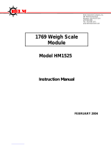
Interface Module Overview
The DH-485/RS-232C Interface Module, catalog number 1747-KE, is a
communications interface module that acts as a bridge between
DH-485 networks and devices requiring DF1 protocol. The DF1 port
on the interface module can be configured for RS-232/423, RS-422, or
RS-485 devices. Residing in an SLC 500 chassis, the module is ideally
used as an interface module, linking remote DH-485 networks via a
modem to a central host.
Interface Module Overview
Interface Module
(1747-KE)
Link Coupler
(1747-AIC)
Modem
Link Coupler
(1747-AIC)
Link Coupler
(1747-AIC)
Remote Network
DH-485
DH-485
Modem
Local Host
AB Parts

Publication 1747-UM005B-EN-P - March 2006
1-2 Overview
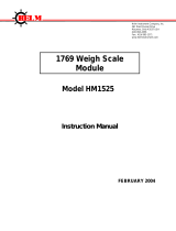
Features
The features of the module are shown below.
1747-KE Module Features
There are three communication ports on the front of the module.
They are:
• CONFIG - used to configure the module with an ASCII terminal.
This serial port accommodates RS-232/423, RS-422, and RS-485
communication interfaces. The CONFIG port is capable of
operating at 300, 600, 1200, 2400, 4800, 9600, and 19200 Kbps. It
is electrically isolated to 500V dc.
• DF1 - used to interface the module to a modem or other user
devices using DF1 protocol. This serial port accommodates
RS-232/423, RS-422, and RS-485 communication interfaces. The
DF1 port is capable of operating at 300, 600, 1200, 2400, 4800,
9600, and 19200 Kbps. It is electrically isolated to 500V dc.
• DH485 - used to interface the module with the DH-485 network.
This port is not isolated and cannot directly drive a multi-node
DH-485 network. You must use a 1747-AIC link coupler to
connect this port to a DH-485 network that includes multiple
SLC 500 processors.
The 1747-C11 or 1747-C13 cables can connect the interface module’s
DH-485 port to a 1747-AIC link coupler. The 1747-C13 cable can also
connect the module’s DH-485 port directly to a single SLC processor.
See page 4-11 for cable connections.
SLC 500
INTERACE MODULE
CAT SER
SERIAL NO.
FRN
12345
6789
CONFIG
12345
6789
DF1
DH485
DH-485/RS-232C
CONFIG
5
4
3
2
1
9
8
7
6
DF1
5
4
3
2
1
9
8
7
6
DH485
JW1
JW2
LEDs
CONFIG
Port
DF1
Port
DH-485
Port
Door Label
JW4
Battery

Publication 1747-UM005B-EN-P - March 2006
Overview 1-3
LED Indicators
There are eight LED indicators on the front of the module. These LED
indicators are used for module diagnostics and operator interface. The
LED indicators and their descriptions are provided below.
LED Indicators
LED Indicator Status
DH
485
/
R
S
-
232
C
DH
485
/
R
S
-
232
C
AC
T
485
C
FG
D
F
1
F
AU
LT
BA
LO W
H
/
D
F/
D
I
N
TE
R
F
AC
E
LED Color Status Indication
ACT Green
ON
(1)
The module is receiving power from the backplane, is configured properly, and
is placed in Run mode.
Flashing The module requires configuration or is being configured.
OFF The module is not receiving power from the backplane. A fault condition
exists.
485 Green ON The DH485 port is active on the network.
OFF The DH485 port is not active on the network or the module is in Configuration
mode.
CFG Green Flashing The CONFIG port is transmitting or receiving signals.
OFF The CONFIG port is not transmitting or receiving signals.
DF1 Green Flashing The DF1 port is transmitting or receiving signals. (The flashing may occur so
rapidly that the LED indicator appears to be on.)
OFF The DF1 port is not transmitting or receiving signals or the module is in
Configuration mode.
FAULT Red ON A system problem was detected during diagnostics. Cycle power to reset. If it
remains on, contact your Allen-Bradley representative.
OFF No system problems are detected during diagnostics.
BA LOW Red ON The voltage of the battery that backs up configuration RAM is low. A new
battery is needed.
OFF The voltage of the battery that backs up configuration RAM is at an
acceptable level.
H/D Amber ON The module is configured for half-duplex DF1 protocol (local or remote).
OFF The module is not configured for half-duplex DF1 protocol.
F/D Amber ON The module is configured for full-duplex DF1 protocol.
OFF The module is not configured for full-duplex DF1 protocol.
(1)
Indicates normal operation after the module has been configured.
AB Parts

Publication 1747-UM005B-EN-P - March 2006
1-4 Overview
Jumper JW1
JW1 lets you to select the communication interface for the CONFIG
port.
Refer to page 4-5.
Jumper JW2
JW2 lets you to select the communication interface for the DF1 port.
Refer to page 4-6.
Jumper JW4
JW4 lets you to select the functionality and mode of the interface
module. The orientation of the jumper determines the module’s
functionality. A horizontal orientation gives the module functionality
equivalent to a series A module (module configuration ID=4209),
while a vertical orientation of the jumper accesses the added
functionality of a series B module (module configuration ID=3509).
The position of the jumper determines the module’s mode
(Configuration or Run), and thus, which method is used to configure
the module (ASCII terminal or backplane communications).
Refer to Chapter 4.
Jumper Placement
SLC 500
INTERACE MODULE
CAT SER
SERIAL NO.
FRN
12345
6789
CONFIG
12345
6789
DF1
DH485
JW1
JW2
JW4

Publication 1747-UM005B-EN-P - March 2006
Overview 1-5
Use a Modem with Your
Interface Module
The module can be connected to most types of dial-up network or
direct connect modems.
The type of modems you can use are:
• Manual - typically acoustically-coupled modems. A person on
each end of the phone line establishes the connection. They
then insert the handsets into an acoustic coupler to complete the
connection.
• DTE controlled answer - these unattended modems are attached
directly to the phone lines. The interface module acts as the
Data Terminal Equipment (DTE), which controls the modem via
the DTR, DSR, and DCD signals. The module incorporates
timeouts and tests to properly operate these types of modems.
• Auto answer - these modems have self-contained timeouts and
tests. They can answer and hang up the phone automatically.
The module has no means of controlling an auto-dial modem,
but it can be used in conjunction with a separate auto-dialer.
• Direct connect - these modems connect to a dedicated, leased
phone line and remain active at all times.
Use DF1 Protocol and Your
Module
RSLinx software supports DF1 communications directly from your
computer’s serial communication port. Connecting a modem to this
port lets you to call remote networks and control them as if you were
connected locally.
DF1 Protocol
IMPORTANT
Some modems are designed to respond to the DTR
signal by answering the phone whether it is ringing
or not. Since the module asserts DTR at all times
(except during the hang-up sequence), the phone
appears to be busy at all times. Do not use the
interface module with any type of modem that
answers the phone as soon as DTR is asserted.
Interface Module
(1747-KE)
DF1 Protocol
DF1 Protocol
Modem
Modem
1747-C13 Cable
DF1
AB Parts

Publication 1747-UM005B-EN-P - March 2006
1-6 Overview
Typical Configurations
The following configurations illustrate some of the possible uses for
the module.
Full-duplex (Point-to-point)
Full-duplex (Point-to-point)
This illustration shows a connection to a single remote SLC node. The
1747-C13 cable eliminates the need for a 1747-AIC link coupler.
Full-duplex (Network, Example 1)
Full-duplex (Network, Example 1)
This illustration shows a connection to a remote DH-485 network of
up to 31 SLC nodes.
Interface Module
(1747-KE)
Modem
Modem
1747-C13 Cable
DF1
Modem
Modem
Link Coupler
(1747-AIC)
Interface Module
(1747-KE)
RSLInx
Link Coupler
(1747-AIC)
Link Coupler
(1747-AIC)

Publication 1747-UM005B-EN-P - March 2006
Overview 1-7
Full-duplex (Network, Example 2)
Full-duplex (Network, Example 2)
This configuration allows the host to call more than one remote
network (one network connected at a time). Each remote network can
consist of up to 31 SLC nodes.
Host computer is capable of
calling and interfacing with
one network at a time.
Modem
Modem
Modem
Modem
Link Coupler
(1747-AIC)
Link Coupler
(1747-AIC)
Link Coupler
(1747-AIC)
Interface Module
(1747-KE)
Interface Module
(1747-KE)
Interface Module
(1747-KE)
RSLinx
Link Coupler
(1747-AIC)
Link Coupler
(1747-AIC)
Link Coupler
(1747-AIC)
Link Coupler
(1747-AIC)
Link Coupler
(1747-AIC)
Link Coupler
(1747-AIC)
AB Parts

Publication 1747-UM005B-EN-P - March 2006
1-8 Overview
Half-duplex (Local Mode)
Half-duplex (Local Mode) Master
This configuration allows the host controller to interface on a remote
DH-485 network of up to 31 SLC nodes using the half-duplex
protocol.
Interface Module
(1747-KE)
Link Coupler
(1747-AIC)
Modem
Modem
PLC-5
processor
Link Coupler
(1747-AIC)
Link Coupler
(1747-AIC)
/