Page is loading ...

®
ODMX-512
DMX512 Input Interface (Class 2 Device) 24 V- 100 mA
For Lutron GRAFIK 5000T, GRAFIK 6000R, GRAFIK 7000T,
and LCP128T Lighting Control Systems
Installation Instructions
Please Leave for Occupant
Description
The ODMX-512 Interface Control provides an
interface between a DMX512/1990 compatible stage
lighting console (provided by others) and a Lutron
lighting control system. The ODMX-512 will read up
to 32 consecutive DMX512 channel levels (select-
able by DIP switches). The ODMX-512 also contains
terminals that allow an external switch to be used as
an input to the lighting control system.
Important Notes:
1. Read all instructions carefully before starting
installation.
2. Install in accordance with all national and local
electrical codes.
3. Turn power OFF at the control panel BEFORE
installing controls. DO NOT connect high-voltage
power to low-voltage terminals. Improper wiring
can result in personal injury or damage to the
control and other equipment.
4. Check with your local electrical inspector for
compliance with local codes and wiring practices.
Installation
1. Prewiring: The Control Links require special wiring
considerations. Refer to your lighting control system
Installation Guide and/or Lutron job drawings for wir-
ing restrictions that may apply to your specifi c project.
2. Turn power OFF to the lighting control system.
!WARNING: Shock Hazard. Always turn off the
power to the control panel before doing any work.
Failure to do so can result in death or serious
personal injury and/or damage to the equipment.
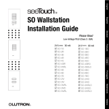
3. Mount the ODMX-512 Interface to a junction box or to
a wall as shown. If the unit is not mounted to a metal
junction box, ensure proper grounding of the metal
casing by connecting a ground wire to the ground
screw. Unscrew and remove the front enclosure cover
to expose the terminal blocks, DIP Switch, and Output
Status LEDs. Insert wires through side knockouts only.
4. Assign Addresses: Address all controls on the
Control Link. Refer to Lutron job drawings for any
preassigned job-specifi c address for each control.
Each Control Link can support up to 32 devices. For
proper system operation, each control on a link must
have a unique address. Set DIP Switch SW1, switches
1-5 on each control to select the Link Address (see
Control Link Address Settings on back of sheet).
Record assignments for future reference.
5. Assign DMX 512 channels to read: Using the unit
label as a guide, set DIP Switch (SW2 DMX Zone
Select) on the unit to the desired group of 32 DMX512
channels to read.
6. Strip insulation from wires so 3/8 in. (9.5 mm) of bare
wire is exposed (terminals will accept up to two
#18 AWG (1.0 mm
2
) wires). If using larger wire, splice
an #18 AWG (1.0 mm
2
) to the larger wire to make the
connection.
7. Connect Control Link wiring as shown in Typical Control
Link Wiring Diagram. Confi rm all connections.
8. Connect external equipment to the DMX512 Input
terminals as shown in the Typical Interface Wiring
Diagram.
9. Replace front enclosure cover. Restore power to the
control panel AFTER the installation of the system is
complete.
MUX LINK
123456
1 2 3 4 5
LUTRON
LED1 LED 2
Output
Status
LEDs
OMX
Control Link
DIP Switch
Control Link
Address
Input from
DMX512
channels
Ground
Screw
CONTR OL LINK
LINK
COM
+V
MU X
MU X
1 2 3 4
DMX 512 INPUT
+
CO M
1 2 3
-
5 6
EXT SW
EXT SW
DMX 512 INPUT
+
CO M
1 2 3
-
1 2 3 4 5
SW1 SW2
DIP Switch
DMX Zone
Select
To External Switch
(by others)
OMX-RS232
3/97 P/N 500-8521 Re vA
INTERFACE CONTROL
SELV (CLASS 2: USA)
COOPERSBURG, PA 18036
ODMX-512
1 2 3 4 5 1 2 3 4 5 1 2 3 4 5
1-32
17-48
33-64
49-80
65-96
81-112
97-128
113-144
129-160
145-176
161-192
177-208
193-224
209-240
225-256
241-272
257-288
273-304
289-320
305-336
321-352
337-368
353-384
369-400
385-416
401-432
417-448
433-464
449-480
465-496
481-512
497-512
1 2 3 4 5 1 2 3 4 5
SW 1
SW 2
Control Link Address
See Instr uction Sheet for Settings
DMX Zone Select
See Belo w
W
A
L
L
ODMX-512
4 in X 4 in
JUNCTION BOX
INSERT LOW-VOLTAGE
WIRES THROUGH
KNOCK OUTS
ODMX-512
W
A
L
L

®
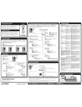
Typical Control Link Wiring Diagram
Wiring Notes:
1. Connection of the control to the Control Link should be made inside the ODMX-512 or in a junction box (provided by
others) located no more than 8 ft (2.5 m) from control.
2. Control link wiring must not be run in the same raceway as line voltage power.
3. Total Control Link length is not to exceed 2000 ft (600 m) unless signal is boosted by a link booster (MX-RPTR).
4. Data cable shield must be maintained throughout the Control Link. DO NOT connect the shield to earth/ground.
5. Refer to your lighting control system Installation Guide and Lutron job drawings for power cable and data cable (Control
Link) wiring restrictions and limitations.
6. Control Link requires a LT-1 (Link Termination Assembly) at each end of the Control Link. Refer to LT-1 instruction sheet for
location and installation information.
• ODMX-512 is one unit load on the DMX512 link as per the
DMX512/1990 and EIA-485 standards.
• Proper DMX512 link wiring practices are required.
• Proper external DMX512 link termination
resistor is needed if the ODMX-512 is at the
end of the DMX512 link.
• Maintained switch closure must be dry or wet
contact closures with:
-On state saturation voltage less than 1.0 V-
- Off state leakage current less than 10 µA
Worldwide Technical and Sales Assistance
If you need assistance, call the toll-free Lutron Hotline:
800.523.9466 (USA, Canada, Caribbean)
Other countries, call 610.282.3800
Fax: 610.282.3090
Lutron will, at its option, repair or replace any unit that is defective in mate-
rials or manufacture within one year after purchase. For warranty service,
call the Lutron Hotline at 800.523.9466 and ask for fi eld service. Lutron
shall, at its option, arrange for repair or replacement of any defective unit.
This warranty is in lieu of all other warranties, express or implied,
and the implied warranty of merchantability is limited to one year
from purchase. This warranty does not cover the cost of installa-
tion, removal, or reinstallation, or damage resulting from misuse,
abuse, or damage resulting from improper wiring or installation.
This warranty gives you specifi c legal rights, and you may also have other
rights which vary from state to state. Some states do not allow the exclu-
sion or limitation of incidental or consequential damages or limitations on
how long an implied warranty may last, so the above limitations may not
apply to you.
Lutron, the Sunburst logo, and GRAFIK 6000 are registered trademarks and GRAFIK
5000, GRAFIK 7000, and LCP128 are trademarks of Lutron Electronics Co., Inc.
©2011 Lutron Electronics Co., Inc.
Typical Interface Wiring Diagram Control Link Address Settings
Warranty
Lutron Electronics Co., Inc.
7200 Suter Road
Coopersburg, PA 18036-1299 USA
Printed in the USA 2/2011 040-378 Rev. A
123456
4
3
2
1
1 2 3 4 5 6
1: WHITE/BLACK
2: RED
3: YELLOW
4: BLUE
43
1 Common
2+V
3 MUX
4 MUX
5 Shield
34
SHIELD
Control
Link
Power
Cable
Data
Cable
1 2 3 4
MUX LINK
123456
1 2 3 4 5
LUTRON
LED1 LED2
EXT SW
DMX 512 INPUT
+
COM
1 2 3
-
1 2 3 4 5
SW1 SW2
OMX-RS232
3/97 P/N 500-8521 RevA
INTERFACE CONTROL
SELV (CLASS 2: USA)
COOPERSBURG, PA 18036
ODMX-512
1 2 3 4 5 1 2 3 4 5 1 2 3 4 5
1-32
17-48
33-64
49-80
65-96
81-112
97-128
113-144
129-160
145-176
161-192
177-208
193-224
209-240
225-256
241-272
257-288
273-304
289-320
305-336
321-352
337-368
353-384
369-400
385-416
401-432
417-448
433-464
449-480
465-496
481-512
497-512
1 2 3 4 5 1 2 3 4 5
SW1
SW2
Control Link Address
See Instruction Sheet for Settings
DMX Zone Select
See Below
Typical Control
(optional)
Control Panel
Control Link
Terminals
Typical ODMX-512 Control
To DMX512/1990
Link
To External Switch
Closure
Last Control on
Control Link
(32 maximum)
LT-1
(Note 6)
Notes 1 & 4 Notes 1 & 4 Notes 1 & 4
LT-1
(Note 6)
To DMX512/1990
Link
COM
+ DATA
– DATA
MUX LINK DMX512 INPUT
123456
To OMX
Control Link
EXT SW
To External
Switch Closure
123
1
2
3
4
5
6
7
8
9
10
11
12
13
14
15
16
17
18
19
20
21
22
23
24
25
26
27
28
29
30
31
32
1 2 3 4 5 1 2 3 4 5 1 2 3 4 5 1 2 3 4 5
SWITCH SETTING
A
DDRESS SWITCH SETTINGADDRESS SWITCH SETTINGADDRESS SWITCH SETTINGADDRESS
SWITCH
UP (ON)
SWITCH
DOWN (OFF)
DIP Switch SW1 settings (switches 1-5)
/