Page is loading ...

UV LIGHT METER
Model : UV-340A
Y
our purchase of this UV
LIGHT METER marks a
step forward for you
into the field of
precision measurement.
Although this METER is
a complex and delicate
instrument, its durable
structure will allow
many years of use if
proper operating
techniques are
developed. Please read
the following
instructions carefully
and always keep this
manual within easy
reach.
OPERATION MANUAL

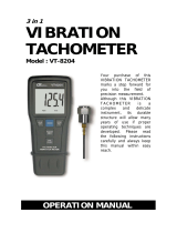
Stora
g
e for the " UV sensor "
UV sensor is with extremely
precise structure. Once don't
use it , be sure to store it in
the dry environment. For
example, put the whole sensor
including Desiccant ( Drier )
into to the Plastic bag and seal
the bag as tightly as possible
( refer the following figure ).
Take the sensor out of the bag only when use it.
Comply to above method will extend the life of UV
sensor. Otherwise, the gain of the UV SENSOR may
be decreased and shorten the calibration period. It is
also necessary to replace the Desiccant ( Drier )
periodically.

TABLE OF CONTENTS
1. FEATURES................................................................1
2. APPLICATIONS......................................................... 1
3. SPECIFICATIONS......................................................2
4. FRONT PANEL DESCRIPTION....................................
.
3
4-1 Display.............................................................. 3
4-2 Power Button.................................................... 3
4-3 Range Switch (Hi/Lo Switch)................................3
4-4 Zero Button....................................................... 3
4-5 Stand.................................................................
.
3
4-6 Battery Compartment/Cover................................ 3
4-7 UV Probe Handle.............................................. 3
4-8 UV Sensor........................................................ 3
5. MEASURING PROCEDURE..........................................4
6. MEASURING CONSIDERATION..................................
.
4
7. BATTERY REPLACEMENT...........................................5

1. FEATURES
* Professional, high quality UV meter.
* Ultra-violet irradiation measurement for UVA & UVB.
* UV detector spectrum from 290 nm to 390 nm.
* Hi, Lo measurement range. 19990 and 1999 uW/cm^2.
* Exclusive UV sensor structure.
* Sensor with cosine correction filter.
* Build Zero button.
* Microprocessor circuit provides high reliability and
durability.
* Separate UV LIGHT probe allows user to measure the
UV light at an optimum position.
* LCD display, easy readout.
* Heavy duty & compact housing case.
2. APPLICATIONS
Industrial
* Monitoring blue light radiation hazards in welding.
* UV sterilization
*Graphic arts.
* Photochemical matching.
* UV EPROM erasure.
* Photoresist exposure.
* Curing of inks, adhesives and coatings.
Laboratory
* Weathering " degradation studies."
* UV sterilization
* Virology.
* Microbial genetics.
* DNA research. * Biologic hoods.
* General laboratory use.
1

3. SPECIFICATIONS
Display LCD size : 18 mm x 45 mm.
Maximum indication 1999.
Measurement
2 ranges : Hi & Lo range
ranges & Lo range : 1999 uW/cm^2 x 1 uW/cm^2
resolution Hi range : 19990 uW/cm^2 x 10 uW/cm^2
* 1000 uW/cm^2 = 1 mW/cm^2
UV sensor Band pass 290 nm to 390 nm.
spectrum
Accuracy ± ( 4 % FS + 2 dgt ) FS : full scale
* Calibration is executed under the UVA light &
and compare with the standard UVA light meter.
* Spec. tested under the environment RF Field
Strength less than 3 V/M & frequency less than the
30 MHz only.
Sensor structure The exclusive UV photo sensor with
the cosine correction filter.
Buttons. Switch Power button, Zero button, Range switch
Sample Time Approx. 1 sec.
Over Range
Indication of " ".
indication
Weight 251 g / 0.55 LB (including battery)
Operating Temp. 0 to 50 .℃
Operating Less than 85% R.H.
Humidity
Power Supply DC 9V battery, 006P , MN 1604 (PP3)
or equivalent.
Power Approx. DC 6 mA.
Consumption
Size Main instrument : 131 x 70 x 25 mm.
Sensor probe head : 45 mm dia x 32 mm.
Sensor probe handle : 125 x 24 mm dia.
Accessories Instruction manual........... 1 PC.
Included UV sensor probe.............. 1 PC.
Optional Acc. Soft carrying case, CA-52A, CA-03.
2

4. FRONT PANEL DESCRIPTION
1
4-1 Display
4-2 Power Button
4-3 Range Switch (Hi/Lo Switch)
4-4 Zero Button
4-5 Stand
4-6 Battery Compartment/Cover
4-7 UV Probe Handle
4-8 UV Sensor
3

5. MEASURING PROCEDURE
1)Push the " Power Button ( 4-2, Fig. 1 ) continuously until
the " Display " ( 4-1, Fig. 1 ) on then release the " Power
Button : will power ON the meter.
* After power ON if push the " Power Button ( 4-2, Fig. 1 )
once a while again will power OFF the meter.
2)Select the max. range on the " Range Switch "
( 4-3, Fig. 1 ).
Lo range : 1999 uW/cm^2 x 1 uW/cm^2
Hi range : 19990 uW/cm^2 x 10 uW/cm^2
* 1000 uW/cm^2 = 1 mW/cm^2
3)Hold the " Probe Handle " ( 4-7, Fig. 1 ) & let " UV Sensor"
( 4-8, Fig. 1 ) face to measuring UV light source , then the
Display ( 4-1, Fig. 1 ) will show values of UV light on the
display reading.
6. MEASURING CONSIDERATION
1)As the " Lo range " is designed & to measure the UV light
values more than 2000 uW/cm^2 . If the measured UV light
values more than 1999 uW/cm^2, it should select the " Range
Switch " to the " Hi range " to get the exact measuring value.
*
Under the " Lo range " if the " Display show " ", it
means the measurement value already over range, then
should select the " Range Switch " ( 4-3. Fig. 1 ) to the
" Hi " position ( 19990 uW/cm^2 range ).
2
)
Zero Button ( 4-4, Fig. 1 ) can be operated under the
Lo range ( 1999 uW/cm^2 range ) and the display
value 100 uW/cm^2 only.≦
4

2)Storage for the " UV sensor "
UV sensor is with extremely precise structure.
Once don't use it , be sure to store it in the dry environment.
For example, put the whole sensor including Desiccant
( Drier ) into to the Plastic bag and seal the bag as tightly
as possible. Take the sensor out of the bag only when use
it. Comply to above method will extend the life of UV
sensor. Otherwise, the gain of the UV SENSOR may be
decreased and shorten the calibration period. It is also
necessary to replace the Desiccant ( Drier ) periodically.
7. BATTERY REPLACEMENT
1)
When LCD display shows " " in the left corner,
It is necessary to replace the battery. However, in-spec
measurement may still be made for several hours after
low battery appears.
2)Slide the " Battery Cover " ( 4-6, Fig. 1 ) away from the
instrument and remove the battery.
3)Replace with 9V battery and reinstate the cover.
4)Make sure the battery cover is secured after changing the
battery.
5
0806-UV340A
/