Page is loading ...

Manual
Accelerometer
PCE-VT 204
PCE Americas Inc.
711 Commerce Way
Suite 8
Jupiter
FL-33458
USA
From outside US: +1
Tel: (561) 320-9162
Fax: (561) 320-9176
www.pce-instruments.com/english
www.pce-instruments.com
PCE Instruments UK Ltd.
Units 12/13
Southpoint Business Park
Ensign way
Hampshire / Southampton
United Kingdom, SO31 4RF
From outside UK: +44
Tel: (0) 2380 98703 0
Fax: (0) 2380 98703 9

TABLE OF CONTENTS
1 FEATURES................................................................
.
1
2 SPECIFICATIONS......................................................
.
3
3 FRONT PANEL DESCRIPTION..................................... 7
3-1 Display..............................................................................................
.
7
3-2 Power button ( vibration )...................................................................7
3-3 Hold/ESC/Zero button.........................................................................7
3-4 Eenter/REC button.............................................................................
.
7
3-5 Function/Send button......................................................................... 7
3-6 Unit/Lo
gg
er button............................................................................. 7
3-7 Operation button ( tachometer ).........................................................
.
7
3-8 Surface speed wheel ( contact tach. ).................................................. 7
3-9 RPM adapter ( contact tach. ).............................................................
.
7
3-10 Protection cover ( contact tach. ).......................................................
.
7
3-11 Screw for protection cover.................................................................
.
7
3-12 Cable plu
g
( vibration sensor )...........................................................
.
7
3-13 Vibration sensor................................................................................
.
7
3-14 Ma
g
netic base................................................................................... 7
3-15 Input socket ( vibration sensor ).........................................................7
3-16 Laser li
g
ht beam ( photo tach. ).........................................................
.
7
3-17 Photo tach. detectin
g
sensor.............................................................. 7
3-18 IR probe input socket........................................................................
.
7
3-19 RS-232 output terminal...................................................................... 7
3-20 Battery cover/battery compartment.................................................... 7
3-21 Cone rubber ( RPM adapter ).............................................................
.
7
3-22 Funnel rubber ( RPM adapter )........................................................... 7
4 VIBRATION MEASURING PROCEDURE........................ 9
5 TACHOMETER MEASURING PROCEDURE....................
.
20
6 IR TEMP. MEASURING PROCEDURE...........................
.
24
7 RS232 PC SERIAL INTERFACE....................................24
8 BATTERY REPLACEMENT...........................................
.
26
9 OPTIONAL ACCESSORIES..........................................
.
26
10 CLASSIFICATION RANGES ( Vibration ).....................
.
27
11 SENSITIVITY RELATIVE TABLE ACCORDING
ISO 2954 ( Vibration ).............................................
.
28

1. FEATURES
Vibration function :
* Applications for industrial vibration monitoring :
All industrial machinery vibrates. The level of vibration
is a useful guide to machine condition. Poor balance,
misalignment & looseness of the structure will cause
the vibration level increase, it is a sure sign that the
maintenance is needed.
* Acceleration range : 200 m/s^2.
* Velocity range : 200 mm/s.
* Displacement ( p-p ) range : 2 mm.
* Metric and imperial display unit .
* RMS measurement for Acceleration and Velocity.
* Peak to peak measurement for Displacement.
* Peak function for Acceleration and Velocity.
* Max. hold function for Acceleration ( peak ),
Velocity ( peak ) and Displacement ( peak to peak ).
* Frequency range 10 Hz - 1 kHz, sensitivity relative
meet ISO 2954.
* Zero function, executed by front buttons.
* Data logger function with flexible sampling time
selection, can save max. 1000-point data into the
memory circuit.
* Data hold button to freeze the desired reading.
* Memory function to record maximum and minimum
reading of RMS value ( Acc., Vel. ) or Displacement ( p-p ).
* Auto shut off saves battery life.
* Professional vibration meter supply with separate
vibration sensor & magnetic base, full set.
1

Tachometer ( photo, contact ) function :
* Laser light detecting source, long measuring range up
to 1.5 meters, it is useful in the RPM measurement
application where the machine would be a risk to the
operator or close access is difficult or not possible.
* The best Tachometer in the world. 2 in 1, one
instrument combine Photo Tachometer & Contact
Tachometer.
* Wide measuring range from 0.5 to 100,000 RPM, 0.1
RPM resolution for the measured value < 1000 RPM.
* Microprocessor based circuit, crystal time base, high
precision with 0.05% accuracy.
* Memory with recall function, the last value, max., value,
min. value will be stored into the memory automatically.
* Patent patented.
General function :
* Super large LCD display.
* No contact infrared temperature measurement via
optional IR temp. probe.
* RS 232 computer interface.
* Optional data acquisition software and data logger
software.
* Microcomputer circuit, high performance.
* Built-in low battery indicator.
* Heavy duty & compact housing case.
* Complete set with the hard carrying case.
2

2. SPECIFICATIONS
2-1 Vibration function
Velocity 0.5 to 199.9 mm/s
range 0.05 to 19.99 cm/s
0.02 to 7.87 in/s
Acceleration 0.5 to 199.9 m/s^2
range 0.05 to 20.39 g
2 to 656 ft/s^2
Displacement 0.005 to 1.999 mm
( p-p ) 0.002 to 0.078 inch
* p-p : Peak to Peak
Frequency 10 Hz to 1 KHz
range
* Sensitivity relative during the
the frequency range meet ISO 2954
Refer to table 1, page 28.
Function Velocity RMS, Peak, Max. hold (peak).
Acceleration RMS, Peak, Max. hold (peak).
Displacement p-p, Max. hold (p-p).
* Peak : To measure the peak value.
* p-p : Peak to peak value.
* Max. hold : To hold the max. peak or p-p value.
Accuracy ± ( 5 % + 2 d ) reading , 160 Hz, 80 Hz.
* 23 ± 5 ℃
Calibration Velocity 50 mm/s ( 160 Hz )
point Acceleration 50 m/s^2 ( 160 Hz )
Displacement ( p-p ) 0.05 mm ( 160 Hz )
Data hold Freeze the desired reading.
3

Memory Maximum & Minimum value.
*
Memory function are only available for
RMS ( Acc., Vel. ) and Displacement (p-p).
Sampling time Approx. 1 second.
Data logger Data logger function with flexible
sampling time selection, can save max.
1000-point data into the memory circuit.
Sampling Time Manual Push the data logger button
of Data Logger once will save the data one
time.
Auto 1, 2, 10, 30, 60, 600, 1800,
3600 seconds.
Sampling time Approx. 1 second.
Power off Auto shut off, saves battery life,
or manual off by push button.
2-2 Tachometer ( photo, contact ) function
Range Photo Tachometer : 10 to 99,999 RPM
Contact Tachometer : 0.5 to 19,999 RPM
Surface Speed ( m/min. ) :
0.05 to 1,999.9 m/min.
Surface Speed ( ft/min. ) :
0.2 to 6,560 ft/min.
Accuracy ± ( 0.05 % + 1 digit ).
Resolution 0.1 RPM < 1,000 RPM
1 RPM 1,000 RPM≧
0.01 m/min. < 100 m/min.
0.1 m/min. 100 m/min.≧
0.1 ft/min. < 1000 ft/min.
1 ft/min. 1,000 ft/min.≧
Time base Quartz crystal
4

Sampling Time Photo Tachometer - 1 sec. ( 60 RPM ).≧
Contact Tachometer - 1 sec. ( 6 RPM ).≧
Photo 50 - 1,500 mm typically.
Tachometer
* Spec. of detecting distance are that under
detecting
the size of reflecting tape is 10 mm square
distance
& the measuring RPM value is 1,800 PPM.
The max. & min. detecting distance may
change under different environment,
different reflecting tape or the measuring
RPM beyond 1800 RPM.
Laser light * Less than 1 mW.
source * Class 2 laser diode. Red. Wave length
* Photo Tach.
is 645 nm approximately.
Memory Last value, Max. value, Min. value.
2-3 General function
Display 45 mm x 48 mm LCD size.
Circuit Exclusive microcomputer circuit.
Data output RS 232 serial output.
Operating 0 to 50 ( 32 to 122 ).℃℉
temperature
Operating Less than 80% RH.
humidity
Power supply 1.5 V battery x 4 PCs
UM-3, AA, R6
Alkaline or heavy duty type,
5

Power Vibration Approx. 10.5 mA
consumption Tachometer Approx. 21 mA
Weight Meter 397 g/0.87 LB
Probe with 110 g/0.24 LB
magnetic base
Dimension Meter :
46.8 x 75.5 x 188 mm
( 1.8 x 3.0 x 7.4 inch ).
Vibration sensor probe:
Round 18 mm Dia. x 40 mm.
Accessories Instruction manual......................... 1 PC.
included Vibration sensor ( VB-82 )..............
.
1 PC.
Magnetic base...............................
.
1 PC.
Reflecting tape marks (600 mm)..... 1 PC.
RPM cone rubber...........................
.
1 PC.
RPM funnel rubber......................... 1 PC.
Carrying Case................................ 1 PC.
Optional * Data Acquisition software,
accessories ................................ SW-U801-WIN
* Data Logger software, SW-DL2005
* RS232 cable.............. UPCB-02
* USB cable.................
.
USB-01
* IR Temp. probe......... IR-962
6

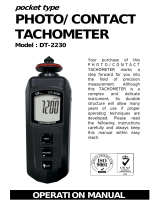
3. FRONT PANEL DESCRIPTION
7 Fig. 1

3-1 Display
3-2 Power button ( vibration )
3-3 Hold/ESC/Zero button
3-4 Eenter/REC button
3-5 Function/Send button
3-6 Unit/Logger button
3-7 Operation button ( tachometer )
3-8 Surface speed wheel ( contact tach. )
3-9 RPM adapter ( contact tach. )
3-10 Protection cover ( contact tach. )
3-11 Screw for protection cover
3-12 Cable plug ( vibration sensor )
3-13 Vibration sensor
3-14 Magnetic base
3-15 Input socket ( vibration sensor )
3-16 Laser light beam ( photo tach. )
3-17 Photo tach. detecting sensor
3-18 IR probe input socket
3-19 RS-232 output terminal
3-20 Battery cover/battery compartment
3-21 Cone rubber ( RPM adapter )
3-22 Funnel rubber ( RPM adapter )
8

4. VIBRATION MEASURING PROCEDURE
4-1 Basic operation procedures
1)Plug in the " Cable plug " ( 3-12, Fig. 1 ) to the
" Input socket of meter " ( 3-15, Fig. 1 ).
2)Power on the meter by pressing the " Power button "
( 3-2, Fig. 1 ).
3)a. For the Acceleration measurement, press the
" Unit button " ( 3-6, Fig. 1 ) once until the display
show the " ACC ", " m/s^2 ", " RMS " symbol
or the " ACC ", " g ", " RMS " symbol.
b. For the Velocity measurement, press the
" Unit button " ( 3-6, Fig. 1 ) once until the display
show the " VEL ", " mm/s " and " RMS " symbol
or the " VEL ", " cm/s " and " RMS " symbol.
c. For the Displacement measurement, press the
" Unit button " ( 3-6, Fig. 1 ) once until the display
show the " DISP(P-P) ", " mm " symbol.
4)If the surface material of measuring article is not the
ferrous material, hold the vibration sensor by hand &
touch the sensor to the surface of the measuring
article, refer the Fig. 2.
Fig. 2
9

5)If the surface material of measuring article is the ferrous
material, connect " Vibration sensor " ( 3-13, Fig. 1 )
with the " Magnetic base " ( 3-14 ), refer Fig. 3.
Put the whole unit ( Vibration sensor & Magnetic
base ) to the surface of measuring article, refer Fig. 4.
Fig. 3
Fig. 4
10

4-2 Unit selection ( Imperial/Metric )
During the measurement, press the " Unit
button " ( 3-6, Fig. 1 ) at least 2 second continuously, the
display unit can be changed from the Imperial unit to
Metric unit or be changed from Metric unit to Imperial
unit.
The Metric unit are :
Acceleration measurement is m/s^2 or g.
Velocity measurement is mm/s or cm/s.
Displacement ( p-p ) measurement is mm.
The Imperial unit are :
Acceleration measurement is ft/s^2.
Velocity measurement is inch/s.
Displacement ( p-p ) measurement is inch.
4-3 Function selection ( RMS/PEAK/MAX HOLD )
During the Acceleration, Velocity, Displacement
measurement if press " Function/Send button "
( 3-5, Fig. 1 ) once can select the following function :
Function Function Function
123
Acceleration ACC ACC ACC
( LCD symbol )
RMS PEAK PEAK MAX HOLD
Velocity VEL VEL VEL
( LCD symbol )
RMS PEAK PEAK MAX HOLD
Displacement DISP(p-p) --------- MAX HOLD
( LCD symbol )
11

1)Function 1 ( RMS for ACC, VEL., p-p for DISP. ) :
Function 1 is the basic operation function, for
general operation select the function 1 typically.
* If Acceleration function measure the " RMS " value,
the display show " ACC " and " RMS " symbol.
* If Velocity function measure the " RMS " value.
the display show " VEL " and " RMS " symbol.
* If Displacement functon measure the " p-p " ( peak to
peak ) value, the display show " DISP ( p-p ) " symbol.
The definition of " peak to peak ", please refer Fig. 6
2)Function 2 ( Peak , for ACC. and VEL, only ) :
* If Acceleration function measure the " Peak " value,
the display show " ACC " and " PEAK " symbol.
* If Velocity function measure the " Peak " value.
the display show " VEL " and " PEAK " symbol.
The definition of " Peak ", refer Fig. 5.
3)Function 3 ( Max. hold, for ACC., VEL and DISP. ) :
* If Acceleration function measure the " Max. peak "
value with hold. the display show " ACC " and " PEAK
MAX HOLD " symbol.
The definition of " Max. peak hold " value, refer Fig. 5.
* If the Velocity function measure the " Max. peak "
value with hold the display show " VEL " and " PEAK
MAX HOLD " symbol.
The definition of " Max. peak hold " value, refer Fig. 5.
12

* The Displacement function measure the max. " p-p "
( peak to peak ) value with hold, the display show "
DISP ( p-p ) " and " MAX HOLD " symbol.
The definition of " peak to peak ", please refer Fig. 6
* Max. hold reset :
If intend rest the " MAX HOLD " value, just
press the " Zero button " ( 3-3, Fig. 1 ) > 2 sec
continuously, the display will return to zero and
make the new max. hold value measurement
again.
Fig. 5
Peak value
Max. peak
value with hold
( ACC., VEL. )
Fig. 6
DISP ( p-p) Max. DISP ( P-P )
value hold
13

4-4 Data hold
During the measurement, push the " Hold button " ( 3-3,
Fig. 1 ) will hold the measured value & the LCD will
show " HOLD " symbol.
Push the " Hold button " again to release the
data hold function.
4-5 Data Record ( Max., Min. reading )
The DATA RECORD function displays the maximum,
minimum readings for the measurement of
Acceleration ( RMS )
Velocity ( RMS )
Displacement ( p-p )
1)Press the " REC button " ( 3-4, Fig. 1 ) once to start the
Data Record function. " REC " will be displayed.
2)With the " REC " symbol on the display :
a)Press the " REC button " ( 3-4, Fig. 1 ) once, the "
REC MAX. " symbol along with the maximum value
will appear on the display.
To delete the maximum value, just press the " Hold
button " ( 3-3, Fig. 1 ) once. The display will show
" REC " and execute the memory function
continuously.
b)Press the " REC button" ( 3-4, Fig. 1 ) again, the
REC MIN. " symbol along with the minimum value
will appear on the display. To delete the minimum
value, just press the" Hold button" ( 3-3, Fig. 1 )
once, then the display will show the " REC " symbol
only and execute the memory function continuously.
14

c) To exit the memory record function, just press the
" REC button " for at least 2 seconds. The display will
revert to the current reading.
4-6 Zero adjustment procedure
Due to drift of environment temperature value, battery
power change or, meter used for a long time or other
reasons. The display value may exist not zero value
( few digits ) in case of no signal into the " Vibration
Sensor ". General speaking those not zero value will not
effect the measurement typically. However if intend to
make the precision measurement, the following zero
adjustment procedures should be executed as :
1)Press the " Function buttion " ( 3-5, Fig. 1 )
to the " Acceleration " position.
2)No signal into the vibration sensor.
3)Press the " Zero button " ( 3-3, Fig. 1 ) continuously
at least 2 second, the display will return to
zero value with default.
4-7 Data Logger
The data logger function can save 1000-point
data for the vibration function.
The data logger procedures are as following :
a)Press the " REC Button " ( 3-4, Fig. 1 ) once to
start the Data Record function and there will be a
" REC. " symbol on the display.
15

b)Auto Data Logger ( Sampling time can select to
1, 2, 10, 30, 60, 600, 1800, 3600 seconds )
Press the " Logger Button " ( 3-6, Fig. 1 ) once to start
the Data Logger function. The " " symbol is
flashed per the sampling time and the data will be
saved into the memory circuit.
Now the Date Logger function is executed.
Manual Data Logger ( Sampling time set to 0
second )
Press the " Logger Button " ( 3-6, Fig. 1 ) once will
save the data one time into the memory circuit.
At the same time the " " symbol will be.
flashed.
Memory full
During execute the data logger function, if the display
show " FULL ",
it indicate the memory data already over
1000 no. and the memory is full.
c) During the Data Logger function is executed, press the
" Logger button " ( 3-6, Fig. 1 ) once will stop to
execute the data logger function, the symbol " "
will be disappeared. If press the " Logger Button "
( 3-6, Fig. 1 ) once again will continuous the Data
Logger function.
16

Remark :
1)
If intend to change the data logger sampling time,
please refer section 4-10/point 4, page 19.
2)
If intend to know the space of balance data
numbers into the memory IC, please refer section
4-10/point 5, page 19.
3)
If intend to clear the saving data from the memory
please refer section 4-10/point 6, page 20.
4-8 How to send the data out from the meter
1)Before sending data out from the meter, exit the "
Hold function " and the " Record " function.
2)Press the " Send Button " ( 3-5, Fig. 1 ) at least 2
seconds until display show " r-232 ", then release the
button.
3)Push the " Send Button " ( 3-5, Fig. 1 ) once, display will
count down, at the same the storage data logger data
will send out the meter from the " RS-232 Output
Terminal " ( 3-19, Fig. 1 ).
4)If intend load the data to the computer, it should
connect the RS232 cable ( optional, model : UPCB-02)
or USB cable ( optional, model : USB-01 ) and apply
the Data Logger software ( optional, Model :
SW-DL2005 ).
17

4-9 Auto power off
The meter is default to auto power off.
If the user intend to disable the " Auto Power off "
function, refer the section 4-10/point 3, page 18.
Note :
During execute the record function, the auto power
function will disable too.
4-10 Advanced setting procedure
1)Power off the meter, first use the finger to press the
the " Hold button " ( 3-3, Fig. 1 ) continuously, then
press the " Power button " ( 3-2, Fig. 1 ) once.
Release the finger from " Hold button ".
2)One by one to press the " Hold button " ( 3-3, Fig. 1 )
once a while to select the five four function and display
will show flashing text with as :
OFF......
.
Auto power On/Off management
SEC...... Change the data logger sampling time
Cnt....... To show the balance data numbers in the memory
CLr.......
.
Clear the existing saving data from the memory
ESC......
.
Escape the advanced setting function
3)
Auto power On/Off
a. Use the " Hold button " to select the main function to
" OFF ".
18
/