Page is loading ...

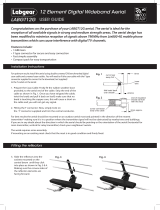
The dipole clips onto the central boom. Ensure that the cable exit
hole (from the terminal box) faces the rear of the aerial and that
the locating stud fits into the locating hole on the boom as
shown in Fig. 1.
•
Wideband - suitable for all UK TV reception areas, covering frequency range 460-790MHz
•
Receives digital TV signals
•
Perfect for use in the majority of locations although in very high strength signal areas an
attenuator may be required, or for very weak strength signal areas an amplifier may be needed
The aerial requires some assembly - please read these instructions carefully before beginning.
Main Features
B. Rotating aerial elements, central
boom and centre mount assembly
A. Fitting the dipole assembly
Congratulations on the purchase of your high gain wideband aerial which is designed to receive locally available digital TV signals.
This aerial is also 4G ready - the design restricts bandwidth to prevent interference & channel loss on your TV caused by signals from 4G
mobile phone transmitters. This aerial has been manufactured to the standard required to get the best reception of digital terrestrial
TV services (such as Freeview™). If the aerial is to be used for DTT reception check before installation at http://www.dtg.org.uk/
industry/coverage.html to conrm that your home is in a coverage area and to nd out where your local transmitter is.
For optimum results install the aerial using double screened digital coax cable and screened coax outlets.
48 Element Digital TV Aerial
27884D4
27884G4
USER GUIDE
Ready
locating
hole
locating stud
rear of aerial
central boom
dipole
Fig. 1
1. Rotate the elements about the central fixing clip until they
‘snap’ into an upright position as shown in Fig. 2.
2. The central boom comes in two sections using the bracket
supplied and the holes drilled in the boom sections join these
two sections as shown in Fig. 3.
3. Attach centre mount bracket in the position shown using the
clips supplied.
1. Using the reflector clamps, screw and large wing nut, fix
the reflector assemblies to the main aerial boom.
2. Check that the reflector clamp tabs locate in the holes
of the reflector boom sections and that the wing nut
is tight - see Fig. 4.
2. Ensure that the reflector elements are facing towards the
front of the aerial (convex surface forward).
C. Fitting the reectors
rotate elements
element
in upright
position
central boom
back section
central boom
front section
joining
bracket
centre mount
bracket with
clips, bolts and
wing nuts
Fig. 2
Fig. 3
engage
tab in hole
reflector
element
reflector boom
assembly
reflector
clamps
Fig. 4

1. Before preparing and stripping the cable ready for connection,
feed the coax cable through the hole in the terminal cover.
2. Prepare cable as shown in Fig. 5.
3. Feed prepared cable through braid clamp and thread the centre
wire through the hole in the central terminal as shown in Fig. 5.
4. Clamp the cable braid securely first, then tighten the screw on
the central terminal. Trim any stray braid that might come into
contact with the centre wire or central terminal.
5. Replace terminal cover carefully and securely making sure that
the cable is not trapped or kinked.
D. Connecting coax cable
CAUTION: When mounting the assembled aerial, always observe
safety precautions and use the correct equipment. Unless you are
competent in the use of ladders and other access equipment, do
not work outdoors at roof height. If in any doubt, refer to a
qualied aerial installer.
braid
centre wire
5mm
10mm
8mm
central
terminal
braid
clamp
No picture: Check all connections from aerial to TV.
Poor picture: Check all connections from aerial to TV.
Check aerial is properly aligned to the correct transmitter.
If the aerial has been loft mounted try mounting outside.
Make sure new digital coax cable has been used throughout the
installation.
Check the transmitter signal is not obstructed by nearby trees or
buildings.
If in a weak signal area or for long cable runs, installing a mast-
head amplifier will improve the signal.
If in a strong signal area the signal strength may need to be
reduced by fitting an attenuator.
E. Coax cable routing and
xingaerialtoamast
For optimum performance it is very important that the coax
cable should be routed as shown in the diagrams opposite.
Fig. 7 shows cable run for this aerial. PVC insulation tape can be
used as shown to hold the cable in place.
For best results the aerial should be centre mounted on an
outdoor aerial mast and pointed in the direction of the nearest
transmitter* making sure it is in a position where the transmitter
signal will not be obstructed by nearby trees and buildings.
If you are in any doubt about the direction in which the aerial
should be pointing or the orientation of the aerial (horizontal for
main transmitter, vertical for relay transmitter) check your
neighbours’ aerials.
When centre mounting, slide the aerial mount back and forth
through mast bracket to find the most evenly balanced position,
this will minimise the strain on the aerial, bracket and mast.
Before mounting check that the mast is in good condition and
firmly fixed.
1. Using the clamp supplied fix the aerial to the mast - see Fig. 7 & 8.
2. After the aerial direction has been fine tuned for best reception
tighten the bolts firmly until the aerial is securely fixed to
the mast.
Please note that this aerial can also be loft mounted.
1x Central boom: assembly square aluminium in 2 sections
joined (L) approx 1240mm with 8x ‘
X’
type elements
2x Reector booms: Square aluminium (L) approx 330mm with
8x Reector elements: Curved aluminium (L) approx 500mm
1x Centre mount bracket with clips: assembly square aluminium
1x Bow tie shaped dipole and printed circuit balun
1x Tilting Mast Clamp
G. Box contents
Tilting
Mast Clamp
Fig. 8
Coax plug wiring instructions
1 Unscrew coax plug housing and slide cap
over cable.
2 Strip 23mm of cable outer sheath.
Gather copper braid, wrap around outer
sheath, slide claw over braid and crimp.
3 Strip 18mm of inner insulation to leave 5mm
exposed
4 Undo screw on plug/clamp, slide clamp over
inner wire & tighten screw. Reassemble plug
1
2
3
4
5
5 Trim inner wire flush with plug.
Fig. 5 Fig. 6
F. Troubleshooting
Adjust aerial to
horizontal position
before tightening bolts
Customer Careline: 08457 573 479
Local rate UK only
Technical Website: www.philex.com/support
E-mail Support: [email protected]
To confirm that your home is in a coverage area, to find
out what DTT channels should be available locally and to
find out where your nearest transmitter is (distance and
compass bearing) visit:
www.dtg.org.uk/industry/coverage.html
© Philex Electronic Ltd 2013. v1.2 www.philex.com
Please Note: Coaxial cable, mountings and masts are not supplied with this aerial. You will need to select these from the range
available according to the specific requirements of your installation. The quality of the coaxial cable used is as important as
the quality of the aerial and you should make sure that if it is not specifically marked as suitable for digital TV it is of the same
quality as that used for digital satellite installations.
PVC
insulation
tape
mast
clamp
Centre mount
bracket
Fig. 7
/