Page is loading ...


1
Thank you for purchasing the Gateway SC- WBGW256.
Before using the product, read this manual thoroughly to ensure you learn how to operate it correctly.
After reading this manual, store it in a safe location for future reference. It will be helpful to reference this
manual should you have any questions or problems. Also read the user’s manual included with the air
conditioner.
▐ PRECAUTIONS FOR WASTE DISPOSAL
Your gateway may be marked with this symbol. It means that waste electrical and
electronic equipment (WEEE as in directive 2012/19/EU) should not be mixed with
general household waste. This gateway should be treated at an authorized treatment
facility for reuse, recycling and recovery and not be disposed of in the municipal waste
stream.
Please contact the installer or local authority for more information.
This symbol printed on the batteries in your gateway is information for end-users
according to the EU directive 2006/66/EC article 20 annex II.
Batteries, at their end-of-life, should be disposed of separately from general household
waste.
If a chemical symbol is printed beneath the symbol shown above, this chemical symbol
means that the batteries contain a heavy metal at a certain concentration. This will be
indicated as follows: Hg:mercury (0.0005%), Cd:cadmium (0.002%) and Pb:lead (0.004%).
Please dispose of batteries correctly at your local community waste collection or recycling
center.

2
Table of contents
■Before you use .............................................................................................................................................. 3
■Safety precautions .................................................................................................................................. 3
■Introduction .................................................................................................................................................... 5
■System outline ........................................................................................................................................ 5
■Personal computer environment ............................................................................................................. 6
■Connections ........................................................................................................................................... 6
■Personal computer initial configuration ................................................................................................... 6
■External dimensions ............................................................................................................................... 8
■Menu item ............................................................................................................................................... 9
■Operation ..................................................................................................................................................... 10
■Basic operation ..................................................................................................................................... 10
●Logging In ....................................................................................................................................... 10
●Overview Monitor screen ................................................................................................................ 11
●Common operations in each screen ............................................................................................... 11
●Individual Monitor screen ................................................................................................................ 13
■Control operation .................................................................................................................................. 14
●Control Command screen ............................................................................................................... 14
●System Stop/Release screen .......................................................................................................... 15
●Schedule Control screen................................................................................................................. 17
■System administrator setting ................................................................................................................ 19
●Configuration Menu screen ............................................................................................................. 19
●Basic Configuration Menu screen ................................................................................................... 20
●Air-conditioner Cell Configuration screen ....................................................................................... 21
●Air-conditioner Cell Configuration File Upload/Download screen .................................................... 23
●Network Configuration screen ......................................................................................................... 25
●Date and Time Configuration screen .............................................................................................. 26
●Security Configuration screen ......................................................................................................... 28
●Authentication Configuration screen ............................................................................................... 29
●Language Configuration screen ...................................................................................................... 30
●Pulse count & DI status Check screen ............................................................................................ 31
●Web Configuration Menu screen .................................................................................................... 32
●WEB Configuration screen .............................................................................................................. 33
●Link Configuration screen ............................................................................................................... 34
●Calendar Configuration screen ....................................................................................................... 35
●Master Schedule Configuration screen ........................................................................................... 36
●Calendar/Schedule Backup File Upload/Download screen ............................................................. 38
●Accounting File Download screen ................................................................................................... 39
●Accounting Period Time screen ...................................................................................................... 40
■Troubleshooting ........................................................................................................................................... 41
■After Sales Service ...................................................................................................................................... 42

3
■Before you use
■Safety precautions
● Please read the precautions written here carefully to operate the gateway properly.
You are required to observe these fully because every item of these instructions is important for
safety.
WARNING
Failure to follow these instructions may result in serious consequences such as
death, severe injury, etc.
CAUTION
Failure to follow these instructions may cause injury, property damage, or serious
consequences depending on the circumstances.
● Failure to follow these instructions may cause injury, property damage, or serious consequences
depending on the circumstances.
Never do.
Always follow the instructions given.
Absolutely keep water away.
Absolutely keep wet hands away.
● Keep this manual in a safe place where you can reference it whenever necessary. Show this
manual to installers when moving or repairing the unit. When the ownership of the gateway is
transferred, this manual and installation manual should be given to a new owner.
● Electrical wiring work must be performed only by qualified specialists.
WARNING
Consult your dealer or a professional contractor to install the unit.
Improper installation made on your own may cause electric shocks, fire or break-down of the
unit.
Consult your dealer when moving, disassembling or repairing the unit.
Never modify the unit.
Improper handling may result in injury, electric shocks, fire, etc.
Avoid using combustible substances (hair spray, insecticide, etc.) near the unit.
Do not use benzene or paint thinner to clean the unit.
It could cause electric shocks or fire.
Stop operation in case of abnormal operation.
If continued, it could result in break-down, electric shocks, fire, etc.
If any abnormal condition (burnt odor, etc.) occurs, stop operation, turn off the power switch
and consult your dealer.
Place this gateway in a location that can be locked for the sake of security, and lock it.
The gateway is equipped with an external power supply terminal block.
Please be sure to place it in a protected location to prevent electric shock and wrongful
operation of the power switch.
Do not take the lid off this gateway.
This gateway has several precision circuit boards.
If you take the lid off, and make a mistake, this gateway could be broken.

4
CAUTION
Do not use or let others use the gateway as play equipment.
Improper operations could cause ill health or health disorders.
Never disassemble the gateway.
If you touch internal parts accidentally, you could get electric shocks or cause trouble.
Consult your dealer when it is necessary to inspect its interior.
Do not wash the gateway with water or liquid.
It could cause electric shocks, fire or break-down.
Do not touch electric parts or operate buttons or switches with wet hands.
It could cause electric shocks, fire or break-down.
Do not dispose of the gateway by yourself.
It could harm the environment. Ask your dealer when it is necessary to dispose of the
gateway.
Note
The gateway should not be installed where it is exposed to direct sunlight or the ambient
temperatures become higher than 40 deg C or lower than 0 deg C.
It could cause deformation, discoloration or break-down.
Do not use benzene, paint thinner, wipes, etc., to clean the gateway.
It could discolor or break-down the gateway. Wipe it with a piece of cloth which is squeezed
tightly after wetting with diluted neutral detergent. Finish up the cleaning by wiping with a
piece of dry cloth.
Do not pull or twist the cables of the gateway.
It could cause break-down.
General precautions
We cannot compensate when monthly calculation was not possible by the trouble of the gateway.
Unit specifications
Item Description
Product dimensions
260 (W) X 140 (H) X 93 (D) mm
Weight
2 kg
Power supply
AC100 / 220–240 V, ±10%, 50/60 Hz
Power consumption
6 W
Usage environment
Temperature: 0 to 40 deg C, Relative Humidity: Below 85% (without condensation)
Material
Casing: SECC
Storage environment Temperature: -20 to 70 deg C, Relative Humidity: 40%–90%
Warning
This is a class A product. In a domestic environment, this gateway may cause radio
interference in which case the user may be required to take adequate measures. This gateway
is not for domestic use.

5
■Introduction
This gateway does centralized monitoring and control of air conditioners from a computer.
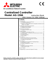
■System outline
The diagram below shows the system configuration. The gateway connected to air conditioners is
connected to the personal computer used for monitoring and control by an Ethernet cable.
A logical unit of monitoring and control is the “Air-conditioner Cell” which consists of air conditioners and
corresponds to a remote control group.
By connecting an electric energy meter or gas meter to this gateway, there is a calculating function that
proportionally divides gas and electricity energy consumption according to the air conditioning usage for
each air conditioning cell.
The calculation is performed on the control and monitoring computer using the included software
"WGW256Utility."
Internet
Explorer
Personal Computer for Control and Monitoring
Ethernet 10Base-T or 100Base-T
X
connecting with a hub or a cross cable
pulse
Gateway
(SC-WBGW256)
DI1
DI3
P1
P2
P3
P4
P5
P6
P7
P8
P
P
P
P
P
P
P
P
SUPERLINK NO. 1 network
∗2
SUPERLINK NO. 2 network
∗2
R
R
R R
R
R
CELL 0
CELL 1
CELL P+1
CELL P+2
CELL Q CELL P
Indoor Unit
IU-0
Indoor Unit
IU-1
Indoor Unit
IU-2
Indoor Unit
IU-126
Indoor Unit
IU-127
Outdoor Unit
OU-0
Outdoor Unit
OU-31
Outdoor Unit
OU-31
Outdoor Unit
OU-0
Indoor Unit
IU-127
Indoor Unit
IU-126
Indoor Unit
IU-2
Indoor Unit
IU-1
Indoor Unit
IU-0
R: remote control
P: electric energy meter or gas meter
∗1: Max 128 indoor units can be
connected in a new SUPERLINK
system for one SUPERLINK
network.
Max 48 indoor units can be
connected in a previous
SUPERLINK system for one
SUPERLINK network.
∗2: It is not possible to mix a new
SUPERLINK network and a
previous SUPERLINK network with
this gateway.

6
■Personal computer environment
●Please check that the computer meets the following specifications
・CPU : 500MHz or higher (2GHz or higher is recommended)
・Memory : 512MB or higher (1GB or higher is recommended)
・Screen size : 1366×768 or higher
●OS and browser
The combination of the OS and Web browser of the control monitoring computer is as follows.
Internet Explorer 10 Internet Explorer 11
Windows 7
OK OK
Windows 8.1
NG OK
Windows 10
NG NG
OK: Can be used, NG: Cannot be used
■Connections
●If a private Ethernet connection is used (recommended)
This method is used to set up a private connection between the gateway and the personal computer
used for monitoring and control.
Connection Method
Connect the gateway and personal computer directly using a 10BASE-T or 100BASE-TX Ethernet
cable (cross cable).
If a hub is used, do not connect other devices to that hub.
●If an Internet or intranet connection is used
If the gateway is connected via the Internet or an intranet (office LAN) environment, please consult with
the dealer. It is possible for them to arrange for connections on a charged work basis.
■Personal computer initial configuration
●Configuration in the case of a private Ethernet connection
Communication settings (TCP/IP settings) in the monitoring and control personal computer are
necessary. For details, please read the operation manual supplied with your personal computer.
If the gateway is used as the factory set IP address, the settings for the computer are as shown below.
・IP Address : 192.168.0.1 - 192.168.0.254
(However, the gateway uses 192.168.0.110, so use an IP address other than this.)
・Subnet Mask : 255.255.255.0
・Default Gateway : Not specified
・Preferred DNS Server : Not specified
・Alternate DNS Server : Not specified
●Configuration in the case of Internet or intranet connections
Please consult with the dealer. It is possible for them to arrange for connections on a charged work
basis.

7
●Browser (Internet Explorer) Configuration
Open Internet Explorer, then select “Internet Options” from the “Tools” menu at the top of the screen
and carry out the following settings.
・In “General”
Home Page http://192.168.0.110/en/
(If you changed the IP address of the gateway, you have to input that IP
address instead of 192.168.0.110 in the address column. By entering the
IP address of the gateway, the gateway login screen will open when your
browser is started.)
・In “Security”
Internet Default Level “Medium”
After clicking the Internet tab, click the “Default Level” button.
Local Intranet Default Level “Medium-low”
After clicking the Local Intranet tab, click the “Default Level” button.
・In “Privacy” Default Level “Medium”
Click the “Default” button.
If the privacy setting is set to “Medium-high” or higher, the gateway cannot
be used, so be sure to set the default value to “Medium.”
・In “Connections” Set it so a proxy server is not used.
・In “Advanced” Default Value
It is recommended that the browser be used with the default values. Click
the “Restore Defaults” button.
When you are finished with all the settings, click the “Apply” button, then click the “OK” button.

8
■External dimensions
Model Name Label
Power switch
LAN
Reset button
Power indicator

9
■Menu item
Login screen
Overview Monitor
screen
Individual Monitor
screen
Air-conditioner Cell
Configuration File
Upload/Download
screen
Control Command
screen
Schedule Control
screen
System Stop/Release
screen
Configuration Menu
screen
Basic Configuration
Menu screen
Air-conditioner Cell
Configuration
screen
Network
Configuration screen
Date and Time
Configuration screen
Security
Configuration screen
Authentication
Configuration screen
Language
Configuration screen
Pulse count & DI
status Check screen
WEB Configuration
screen
Link Configuration
screen
Web Configuration
Menu screen
Calendar
Configuration screen
Master Schedule
Configuration screen
Calendar/Schedule
Backup File
Upload/Download
screen
Accounting File
Download screen
Accounting Period
Time screen
BACnet Configuration
Menu screen

10
■Operation
■Basic operation
●Logging In
The login screen is the starting screen for the gateway. The login screen is displayed by inputting the
URL of the gateway from the computer’s web browser.
1. Start the computer’s browser (Internet Explorer).
2. Input the following URL, http://192.168.0.110/en/, in the address bar, then press
the Enter key.
If your gateway’s IP address has been changed, the above IP address “192.168.0.110” should be
replaced by the new IP address.
Login screen
3. Input the User ID and Password
This screen is a screen for logging in to this gateway and authenticating the user who performs
control monitoring operation with the user ID and password.
There are differences in authority depending on the user who logs in, with the following three
categories of authority.
- System Administrator : Can operate all screens.
- Control and Monitoring User : Cannot operate the Configuration menu.
- Monitoring User : Is authorized to use the monitoring screen only and
cannot perform any control operations.
・Factory default user ID and password of each user
User Category user ID password
System Administrator Admin 123456
Control and Monitoring User Controller 123456
Monitoring User User 123456
4. Click the “Login” button.
Note
The User ID and Password can be changed in the Authentication Configuration screen. (See page 29.)
Click the "日本語に切替" button to switch to the Japanese display.
3
2
4

11
●Overview Monitor screen
This screen is displayed when you log in.
This screen is for monitoring the overview of the whole air conditioner system. It is capable of monitoring
up to 256 Air-conditioner Cells (air conditioner remote control group connection units). It displays the name
of each Air-conditioner Cell, an error display icon, and the On/Off/Operation Mode icon.
Note
・ The Overview Monitor screen is refreshed automatically (automatic update) at regular intervals.
Refreshing the screen may take several seconds depending on the network’s status and the computer’s
performance.
The refresh interval can be set to 10-180 seconds. (See page 33.)
・ The characters and icons on the screen might move slightly when the screen is refreshed, but this is a
characteristic of Internet Explorer.
Overview Monitor screen
●Common operations in each screen
1. Displaying a different gateway (when multiple gateways are connected)
Currently, the Overview Monitor screen of the gateway on the left end is displayed. To display the
screen of other gateways, click the name of the gateway.
2. Displaying a different function screen
To display each function screen, click the function screen name (“Control Command”, “Schedule
control”, etc.) from the menu at the top of the screen.
3. To log out
Click “Logout” from the menu at the top of the screen.
You will be logged out and return to the login screen.
3
1
2

12
・ When “Buzzer ON” is selected on the WEB Configuration screen, the alarm buzzer function that gives the
warning by sounding the buzzer when any error has occurred in an Air-conditioner Cell, is enabled. (See
page 33.)
The alarm buzzer function works not only on this screen but also on any screen of this gateway.
When the buzzer is sounding, the Buzzer Off button is shown at the left side of the screen on all screens.
Overview Monitor screen when the buzzer is sounding
4. To stop the buzzer
・ Click the “Buzzer Off” button. This stops the buzzer sounding on the Overview Monitor computer
connected to this gateway.
・ Since the volume of buzzer sound is set on the Overview Monitor computer, adjust the volume, if
necessary, on the computer.
・ When the buzzer sounds while this screen is minimized, maximize the screen, and then click the
Buzzer Off button.
・ When the window for another application is in front of the Internet Explorer window, bring this screen
to the front, and then click the Buzzer Off button.
Note
If the login screen is displayed when you click the link on the screen such as “Control Command”, that
means the power of the gateway was turned off and on again. Please log in again. (See page 10.)
4
5

13
●Individual Monitor screen
This screen is for indicating the detailed information on one Air-conditioner Cell in a pop-up window on the
Overview Monitor screen.
5. Click the name of the Air-conditioner Cell you would like to monitor on the Overview
Monitor screen.
The individual monitor screen will be displayed in a pop-up window.
Note
・ The Individual Monitor screen is refreshed automatically (automatic update) at regular intervals.
Refreshing the screen may take several seconds depending on the network’s status and the
computer’s performance.
The refresh interval can be set to 10-180 seconds. (See page 33.)
・ The characters and icons on the screen might move slightly when the screen is refreshed, but this is a
characteristic of Internet Explorer.
After the pop-up window opens, clicking a different Air-conditioner Cell name will cause the previously
opened pop-up window to close and a new pop-up window to open in the same place.
Individual Monitor screen
・Operation Status
On : At least one air conditioner is running in the Air-conditioner Cell.
Off : All air conditioners have stopped in the Air-conditioner Cell.
The operation mode of the running air conditioner with the smallest address in the Air- conditioner Cell
is shown.
・Failure Status
Normal : All air conditioners in the cell are not malfunctioning.
Failure : One or more air conditioners in the cell are malfunctioning.
・FAN, SET TEMP., ROOM TEMP., LOUVER, LOCK
The current state of the running air conditioner with the smallest address in the Air- conditioner Cell is
shown.
・Filter sign
On : At least one air conditioner's filter sign is on in the Air-conditioner Cell.
Off : All air conditioners' filter signs are off in the Air-conditioner Cell.
・ERROR CODE
The error code for the air conditioner with the smallest address in the Air- conditioner Cell is shown.

14
2
■Control operation
You can use the control operation only when you log in as "System Administrator" or "Control and
Monitoring User".
●Control Command screen
Use this screen to set the control commands for each Air-conditioner Cell.
Note
In some models of air conditioners, it is not possible to set and display "POWERFUL".
If you select anything other than blank in an item in the ALL row, the settings will be applied to all
registered Air-conditioner Cells.
1. Click “Control Command” from the menu at the top of the screen.
The Control Command screen will be displayed. (Displaying the screen may take several seconds
depending on the state of the network, etc.)
The current setting status is displayed.
2. Select control command values from the pull-down menus for each control item.
Select each control command value, if necessary.
The setting range of the set temperature is limited as follows depending on the operation mode.
・
On/Off : On / Off
・
Mode : Auto / Cool / Dry / Fan / Heat
・
Fan Speed : Powerful / High / Medium / Low
・
Set Point : 16-30 deg C (Mode : no setting)
( 0.5 deg C intervals) 10-30 deg C (Mode : Heat)
16-35 deg C (Mode :
other than Heat)
・
Louver : Swing / Stop1 / Stop2 / Stop3 / Stop4
・
Remocon Lock : Lock / Unlock
・
Filter Sign : RESET (turn off the filter sign)
・
Failure : If an error occurs, an error code is displayed. Operation is not possible.
3. Click the Set button.
The contents set in step 2 above are transmitted to the Air-conditioner Cells.
Control Command screen
3

15
2
●System Stop/Release screen
Use this screen to stop or release all the air conditioners connected to the gateway.
<System Stop>
1. Click “System Stop/Release” from the menu at the top of the screen.
The System Stop/Release screen will be displayed.
2. Click the “System Stop” button.
All the air conditioners under this gateway immediately stop and are set to the Remote control Lock
mode. Then, the screen will return to the Overview Monitor screen.
Even if a system stop command is received from the host computer by BACnet communication, or
when the contact connected to the system stop input terminal (DI1) becomes "closed" by a fire alarm
device, etc., it will be forcibly stopped.
System Stop/Release screen

16
1
<System Release>
1. Click the “System Release” button during a System Stop.
The stop setting for all air conditioners will be released, the Overview Monitor screen will be displayed,
and the scheduled operation from that point on will be enabled.
The remote control operation returns to the state before the System Stop.
Note
・ While the contact connected to the system stop input terminal (DI1) is "closed", the stopped state
cannot be released by this screen. The system stop condition becomes released when the contact
connected to the system stop input terminal (DI1) becomes "open" in the state where two minutes or
more has passed since the system stop condition by terminal (DI1) was started.
・ Even when the system stop condition becomes released, the air conditioners will not start operating
automatically. Start the operation manually.
System Stop/Release screen during a System Stop

17
●Schedule Control screen
This screen displays the Schedule Control composed of the Master Schedule and calendar for each
Air-conditioner Cell, and is used to input data and edit the Schedule Control. Every day, at the change of
the date, the data of the Schedule Control is shifted by one day, and one day's data is copied from the
Master Schedule to the 7th day's schedule data of the Schedule Control.
Note
・ If you want to change the schedule within 7 days from the current day, change the schedule in this
Schedule Control screen.
・ If you jump to the screen for another month without clicking the Set button, or if you click the “Undo”
button, all the contents input in this screen will be deleted, so exercise caution.
・ If you click the “Undo” button, the contents input will be deleted and the saved content is displayed again.
・ Clicking the “Load Master” button causes the schedule to be loaded from the annual calendar and
Master Schedule and displayed on the screen. If the “Set” button is then clicked, the Schedule Control is
set from the Master Schedule.
・ The instructions and display contents in this screen can be copied to another Air-conditioner Cell or
another date. Select the Air-conditioner Cell name and corresponding schedule date that is the
destination, then click “Copy”. When "ALL" is selected, the settings are copied to all the Air-conditioner
Cells.
・ This gateway updates the Schedule Control once a day at 00:00 in the middle of the night.
・ The actual operation schedule is in accordance with the Schedule Control displayed in this screen, but
when the system is operated using the remote control, etc., it may not run in accordance with the
schedule.
・ When all the air conditioners stop by system stop, not only does operation stop, but the entire Schedule
Control will not be executed.
・ In some models of air conditioners, it is not possible to set and display "POWERFUL".

18
3
1. Click “Schedule Control” from the menu at the top of the screen.
In the initial screen, the Schedule Control of the cell with the lowest cell No. is displayed.
(It may take several seconds to display this screen depending on network conditions.)
Schedule Control screen
2. Select the Air-conditioner Cell name and corresponding schedule date.
Select the Air-conditioner Cell name and corresponding schedule for the Air-conditioner Cell that is
being displayed and edited. A seven-day Schedule Control from the current day to 6 days in advance
can be displayed and edited.
3. Select and input each schedule item.
The following items can be set as schedule items in this screen.
・Time : 00:00–23:59 (1-minute intervals)
・On/Off : Blank (not specified), On, Off
・Mode : Blank (not specified), Auto, Heat, Cool, Fan, Dry
・Fan Speed : Blank (not specified), Powerful, High, Medium, Low
・Set Point : Blank (not specified), Depending on the operation mode, it can be
selected within the following ranges. (0.5ºC increments)
・16-30 deg C (Mode : no setting)
・10-30 deg C (Mode : Heat)
・16-35 deg C (Mode : other than Heat)
・Remocon Lock/Unlock : Blank (not specified), Lock, Unlock
One time can be set with a combination of up to 5 items (On/Off, Mode, Fan Speed, Set Point,
Remocon Lock). Up to 20 settings can be set.
4. Click the “Set” button.
4
2

19
■System administrator setting
You must log in as a system administrator to make these settings.
●Configuration Menu screen
This screen is displayed when “Configuration Menu” is clicked from the menu at the top of the screen.
The following Configuration menus are available.
- Basic Configuration Menu
- Web Configuration Menu
- BACnet Configuration Menu
Note
The BACnet function setting screen is not used. Click the return button to return to the setting menu
screen.
Configuration Menu screen
/