Mitsubishi Heavy Industries SC-SL4-BE User manual
- Category
- Split-system air conditioners
- Type
- User manual
This manual is also suitable for

This center console complies with EMC Direcve 2014/30/EU, LV
Direcve 2014/35/EU, RoHS Direcve 2011/65/EU.
CE marking is applicable to the area of 50 Hz power supply.
Cee console centrale est conforme à la direcve CEM 2014/30/UE,
à la direcve basse tension 2014/35/UE et à la direcve RoHS
2011/65/UE.
La marque CE s'applique aux régions alimentées en courant de 50 Hz.
Diese Mielkonsole erfüllt die Richtlinien zur elektromagneschen
Verträglichkeit 2014/30/EU, die Niederspannungsrichtlinien
2014/35/EU und die RoHS-Richtlinie 2011/65/EU.
Die CE-Marke gilt für Bereiche mit einer Netzstromversorgung von
50 Hz.
Questa console centrale è conforme alla Direva EMC 2014/30/UE,
alla Direva LV 2014/35/UE e alla Direva RoHS 2011/65/UE.
Il marchio CE è applicabile alla fascia di alimentazione 50 Hz.
Esta consola central cumple con la Direcva de Compabilidad
Electromagnéca 2014/30/UE, con la Direcva de Baja Tensión
2014/35/UE y con la Direcva RoHS 2011/65/UE.
La indicación CE solo corresponde al área de suministro eléctrico de
50 Hz.
Esta consola central está em conformidade com a Direva EMC
2014/30/UE, a Direva LV 2014/35/UE e a Direva RoHS
2011/65/UE.
A marca CE aplica-se à zona de fornecimento de energia a 50 Hz.
Αυτή η κεντρική κονσόλα συμμορφώνεται προς την Οδηγία
2014/30/ΕΕ περί ηλεκτρομαγνητικής συμβατότητας , προς την
οδηγία 2014/35/ΕΕ περί χαμηλής τάσης και προς την Οδηγία
2011/65/ΕΕ περί RoHS.
Tο σήμα CE ισχύει μόνον σε περιοχές όπου η τροφοδοσία είναι
50 Hz.
Этот центральный пульт управления соответствует
требованиям директивы по электромагнитной
совместимости 2014/30/EU, директивы по низковольтному
оборудованию 2014/35/EU, директивы RoHS 2011/65/EU.
Маркировка CE нанесена в области источника питания,
работающего на частоте 50 Гц.
Bu orta konsol, 2014/30/EU sayılı EMC Direkfi, 2014/35/EU
sayılı LV Direkfi ve 2011/65/EU sayılı RoHS Direkfi ile
uyumludur.
CE işare, 50 Hz güç kaynağı için geçerlidir.
Sterownik centralny spełnia wymagania dyrektywy EMC
2014/30/EU, dyrektywy niskonapięciowej 2014/35/EU oraz
dyrektywy RoHS 2011/65/EU.
Oznakowanie CE dotyczy wyłącznie regionów, w których
częstotliwość napięcia zasilającego wynosi 50 Hz.
Deze centrale console voldoet aan EMC-Richtlijn 2014/30/EU,
LV-Richtlijn 2014/35/EU, RoHS-Richtlijn 2011/65/EU.
CE-markering is van toepassing op het gebied met een netstroom
van 50 Hz.
201803
PJZ012A173

– 1 –
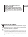
ENGLISH
Before using, read thoroughly this user’s manual for proper
operation. After reading, carefully store it for future reference. If
any trouble should occur during operation, it will be helpful. Also,
read thoroughly the user’s manual which is attached to the air
conditioner.
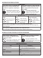
❚ PRECAUTIONS FOR WASTE DISPOSAL
Your central control may be marked with this symbol. It means that waste electrical and
electronic equipment (WEEE as in directive 2012/19/EU) should not be mixed with general
household waste. Central control should be treated at an authorized treatment facility for re-
use, recycling and recovery and not be disposed of in the municipal waste stream. Please
contact the installer or local authority for more information.
This symbol printed in the batteries attached to your central control is information for end-
users according to the EU directive 2006/66/EC article 20 annex II.
Batteries, at their end-of-Iife, should be disposed of separately from general household waste.
If a chemical symbol is printed beneath the symbol shown above, this chemical symbol means
that the batteries contain a heavy metal at a certain concentration. This will be indicated as
follows:Hg:mercury (0.0005%), Cd:cadmium (0.002%), Pb:lead(0.004%)
Please, dispose of batteries correctly at your local community waste collection or recycling
center.
Thank you for purchasing Central Control
SC-SL4-AE, SC-SL4-BE.

– 2 –
Table of contents
Safety Precautions ....................................... 3
Introduction .................................................. 5
Overview ....................................................................... 5
Names and Functions of Parts ..................................... 5
Blocks, Groups ............................................................. 6
Startup Screen .............................................................. 6
Quick Reference Chart for Operations ......................... 8
Menu ............................................................................. 9
Operator Menu Screen ............................................... 10
All Blocks Display ........................................................11
Changeover Confi rmation Screen .............................. 12
Icons ........................................................................... 12
Operation .................................................... 14
Group Operation Settings (Monitor Group Status) ..... 14
Multiple Groups Operation Settings ............................ 19
Group Batch Operation ............................................... 22
Schedule Settings ....................................................... 24
Viewing Detailed Unit Information ............................... 30
Calculating Settings (SC-SL4-BE only) ...................... 31
Initial Settings ............................................. 33
Group Defi nition .......................................................... 33
Block Defi nition ........................................................... 37
Time & Date Setting .................................................... 40
Convenient Functions ................................ 42
Entering Numbers and Characters ............................. 42
Display Setting ............................................................ 43
Corrections for Power Outage .................................... 44
Using USB Memory .................................................... 44
Operation Time History ............................................... 46
Energy Consumption History (SC-SL4-BE only) ........ 47
LAN Settings ............................................................... 48
Operator Settings ........................................................ 49
Function Setting .......................................................... 50
Temperature Range Setting ........................................ 50
Control Function Setting ............................................. 51
Home Leave Setting ................................................... 52
Data Logging .............................................................. 54
Flap Control Setting .................................................... 55
Group User Setting ..................................................... 56
Viewing Alarm History ................................................. 58
System Information ..................................................... 58
Help ............................................................................ 58
Maintenance ................................................ 59
Shutdown .................................................... 60
Using MAINTENANCE MENU .................... 61
Unit Defi nition Settings (SC-SL4-BE only) .................. 62
Outdoor Unit Defi nition ............................................... 63
Import/Export Confi guration File ................................. 64
Meter Defi nition (SC-SL4-BE only) ............................. 66
Operation Data Monitoring .......................................... 66
Maintenance User Setting .......................................... 67
Function Setting .......................................................... 68
SL Mode ...................................................................... 69
Function Settings Details ............................................ 70
External Input Settings ................................................ 71
Language Setting ........................................................ 72
Factory Clear .............................................................. 73
Viewing Alarm History ................................................. 74
External Input Status .................................................. 75
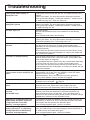
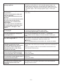
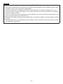
Troubleshooting ......................................... 76
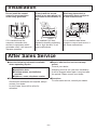
Installation .................................................. 79
After Sales Service ..................................... 79

– 3 –
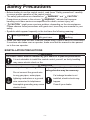
Safety Precautions
• Before starting to use the central control, read these “Safety precautions” carefully
to ensure proper operation of the central control.
• The safety precautions are classifi ed as “ WARNING ” and “ CAUTION ”.
Precautions as shown in the column “ WARNING ” indicate that improper
handling could have serious consequences like death, serious injury, etc.
• “ CAUTION ” might pose a serious problem, depending on the circumstances.
Please observe these precautions with great care, since they are essential to your
safety.
• Symbols which appear frequently in the text have the following meaning:
Strictly prohibited.
Observe instructions
with great care.
Provide positive
earthing.
• When you have read the user’s manual, please keep it near at hand for consultation.
If someone else takes over as operator, make sure that the manual is also passed
on to the new operator.
❚ INSTALLATION PRECAUTIONS
WARNING
The central control must be installed by your dealer or a qualifi ed professional.
It is not advisable to install the central control yourself, as faulty handling
may cause electric shock or fi re.
CAUTION
Make sure to perform grounding work. Depending on the place of installation, a
leakage breaker may be necessary.
Do not connect the ground wire
to any gas pipes, water pipes,
lightning conductors or a ground
wire connected to telephones.
Incomplete grounding may cause
electric shock.
If a leakage breaker is not
installed, electric shock may
happen.
Consult your dealer.

– 4 –
❚ OPERATION PRECAUTIONS
WARNING
If the central control is damaged with
water due to a natural disaster such
as a fl ood or a typhoon, consult your
dealer.
If the central control is under abnormal
conditions, stop the operation, turn the
power supply switch off and consult
your dealer.
Operating the central control
under such conditions may lead
to failure, electric shock and/or
fi re.
Continuing operating the
central control under abnormal
conditions may lead to failure,
electric shock and/or fi re.
CAUTION
Do not handle with wet
hands.
Do not pull the connecting
wire.
Do not wash the central
control with water.
This may cause an
electric shock or
failure.
If the core wire
is disconnected,
it could cause a
short-circuit.
It may cause
electric shock or
failure.
A static electric discharge to the unit could cause a break-down.
Before performing operations, touch a grounded metal object and discharge any
static electricity.
Do not perform repetitive operations with signifi cant force.
The touch panel will deteriorate, and screen response may worsen.
❚ PRECAUTIONS FOR RELOCATION OR REPAIR
WARNING
Never modify or disassemble the
central control. If it requires service,
consult your dealer.
If it is required to relocate the central
control, consult your dealer.
If servicing is inadequate, electric
shock and/or fi re may occur.
Improper installation of the
central control may cause electric
shock and/or fi re.
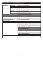
Unit specifi cations
Item Description
Product dimensions
250 (W) x 172 (H) x (23+70) (D) mm
(70 is the embedded measurement)
Weight 2 kg
Power supply AC100–240W 50/60 Hz
Power consumption 9 W
Usage environment Temperature: 0 to 40 deg C
Material Casing: ABS

– 5 –
Introduction
Overview
Central controls are made to collectively control air conditioning indoor units. All the controls such as
unit monitoring, operation, settings and scheduling can be done on the touch panel.
Warning
This is a class A product. In a domestic environment, this product may cause radio interference in
which case the user may be required to take adequate measures. This unit is not for domestic use.
Important!!
The energy consumption calculated by this unit does not conform to OIML, and there are no
guarantees concerning the results of the calculations.
This unit calculates only energy consumption distribution (gas, electric power). You need to calculate
the air- conditioning rates.
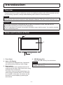
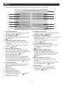
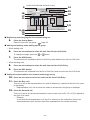
Names and Functions of Parts
1
2
3
4
1. Front Cover
2. Color LCD Display
The screens are displayed here. Operations
are performed by touching it with a fi nger.
3. Reset switch
Press the switch that is placed innermost of
small hole at the lower side of this cover, using
a straight clip or similar tool.
The screen may be locked depending on the
static charge or external noise, etc, but there
is no trouble. In this case, the screen can be
returned to normal display by pressing the
reset switch.
4. USB Memory Slot
Insert the USB memory from the bottom.
Warning
Do not insert any USB device other than the
bundled USB memory.

– 6 –
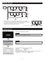
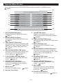
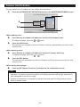
Blocks, Groups
[Example of Connections]
Air conditioner
1
Central
control
R
R
R
R
R
R
Air conditioner
16
Air conditioner
2
Air conditioner
17
Air conditioner
4
Air conditioner
19
Group 1
Group Q +1
Group 2
Block 2
Group Q
Group R
Air conditioner
3
Air conditioner
18
Air conditioner
5
Air conditioner
20
Block 1
Air conditioner
15
Air conditioner
P
• A maximum of 16 air conditioner can be set up in one group.
• Do not use one remote controller for different groups of air conditioner.
• A maximum of 12 groups can be set up in one block.
• A maximum of 20 blocks can be set up.
Air conditioner
1
R
Air conditioner
2
Air conditioner
4
Group 1 Group 2
Air conditioner
3
R : Remote controller
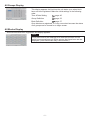
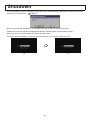
Startup Screen
[Startup screen]
This screen is displayed at startup.
Note
It may take time to display the screen.
[Information screen]
Note
It is not possible to do any setting when information screen is
displayed.
[Login screen]
The default ID and password are as follows:
Default ID:
Default password:
OPERATOR
123456
After logging in, change the default ID and password to your own.
Changing the ID and password
page 49

– 7 –
All Groups Display
This display appears the fi rst time the unit starts up or when block
have not been registered. Make the initial settings in the following
order.
Time & Date Setting
page 40
Group Defi nition
page 33
Block Defi nition
page 37
Once blocks are registered, it is very convenient because the status
of all groups can be viewed on a single screen.
All Blocks Display
When blocks have been registered, this display appears.
Note
It may take time for the settings to be read into the unit. Do not
perform any operations until all the groups that have been set are
displayed. (This should take only a few minutes.)

– 8 –
Quick Reference Chart for Operations
Initial settings Date & time Page 40 (Time & Date Setting)
Groups Page 33 (Group Defi nition)
Blocks Page 37 (Block Defi nition)
Viewing status All blocks Page 11 (All Blocks Display)
All groups Page 18 (All Groups Display)
Each group Page 14 and 17 (Group Operation Settings : BLOCK
LAYOUT & GROUP LIST screen)
Each unit Page 30 (Viewing Detailed Unit Information)
Group operation Page 14 (Group Operation Settings)
Multiple groups operation Page 19 (Multiple Groups Operation Settings)
Batch operation Page 22 (Group Batch Operation)
Setting and checking schedules Page 24 (Schedule Settings)
Making calculating settings
(SC-SL4-BE only)
Page 31 (Calculating Settings)
Entering numbers and characters Page 42 (Entering Numbers and Characters)
Using convenient functions Page 43 (Display Setting)
Page 44 (Corrections for Power Outages)
Page 44 (Using USB Memory)
Page 46 (Operation Time History)
Page 48 (LAN Setting)
Page 49 (Operator Settings)
Page 50 (Function Setting)
Page 54 (Data Logging)
Page 55 (Flap Control Setting)
Page 56 (Group User Setting)
Page 58 (System Information)
Alarm history Page 58 and 74 (Viewing Alarm History)
Further Information Page 58 (Help)

– 9 –
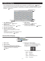
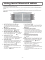
Menu
When the MENU button is pressed, the screen switches to the one shown below.
1 10
9
8
2 11
3 12
4
13
5
146
15
7
1. ALL BLOCKS button
Displays a list of the names and status of all
blocks in a panel. page 11
2. ALL GROUPS button
Displays all group names and status in a list.
page 18
3. OPERATION TIME HISTORY button
Displays operation time in graph format for
each group.
(If you have not set a group, this button is
invalid.)
page 46
4. DISPLAY SETTING button
Sets the brightness of the display and the
light-up period of the backlight, or switches to
screen cleaning mode.
page 43
5. OPERATOR MENU button
Switches the screen for making group and
block settings, date and time settings and
accounting settings (SC-SL4-BE only) as well
as viewing the alarm history.
page 10
6. SHUTDOWN button
When it is known that there will be a power
outage, this button saves the settings.
page 60
7. LOGOUT button.
Return to login screen.
8. Outdoor air temperature
You can choose outdoor unit.
page 63
9. Date and Time display
10. CHANGE ALL button
Switches the screen for changing group batch
operation settings.
page 22
11. SCHEDULE SETTING button
Switches the screen for setting air conditioning
operation schedules.
(If you have not set a group, this button is
invalid.)
page 24
12. SYSTEM INFORMATION button
Displays the central control version number
and number of units registered.
page 58
13. MAINTENANCE MENU button
Displays the MAINTENANCE MENU.
This button is displayed only when you have
logged in using the maintenance user ID.
page 61
14. RUN ALL/STOP ALL button
Stops running for groups set up for batch
operation.
(Settings can also be made for groups not set
up for batch operation.
page 33
15. HELP button
Opens the screen for viewing detailed
information on the display content and
operations.
page 58

– 10 –
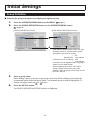
Operator Menu Screen
This is displayed when the OPERATOR MENU button is pressed on the MENU screen.
page 9
1
2
3
4
5
6
7
9
8
16
10
11
12
13
14
15
1. BLOCK DEFINITION button
Switches the BLOCK DEFINITION screen.
page 37
2. GROUP DEFINITION button
Switches the GROUP DEFINITION screen.
page 33
3. FUNCTION SETTING button
Switches to the screen for TEMPERATURE
RANGE SETTING, CONTROL FUNCTION
SETTING and HOME LEAVE SETTING.
page 50
4. ACCOUNTING PERIOD TIME button
Switches to the screen used to set the start
and end time of the accounting period.
(SC-SL4-BE only)
page 31
5. FLAP CONTROL SETTING button
Switches the FLAP CONTROL SETTING
screen.
page 55
6. OPERATOR SETTING button
Switches to the screen used to set the
operator ID and password, and operator
information.
page 49
7. MENU button
Returns to the MENU screen.
page 9
8. Date and Time display
9. LAN SETTING button
Switches to the screen used to set the IP
address, subnet mask, and gateway address.
page 48
10. TIME & DATE SETTING button
Switches the TIME & DATE SETTING screen.
page 40
11. DATA LOGGING button
Switches the DATA LOGGING screen.
page 54
12. EXPORT MONTHLY DATA FILES button
Switches to the screen used to export the
accounting period data and save it on a USB
memory device. (SC-SL4-BE only)
page 44
13. ALARM HISTORY button
Displays the Alarm History of the units.
page 58
14. GROUP USER SETTING button
Switches the GROUP USER SETTING
screen.
page 56
15. HELP button
Opens the screen for viewing detailed
information on the display content and
operations.
page 58
16. Outdoor air temperature
You can choose outdoor unit.
page 63

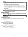
– 11 –
All Blocks Display
This is displayed when the ALL BLOCKS button is pressed on the MENU screen. page 9
The names and the status of all blocks are displayed in the panels. Unestablished blocks or blocks
without any groups are not displayed. If a block button is pressed, the BLOCK LAYOUT screen is
displayed.
page 14
2
1
3
6
5
4
1. ALL GROUPS button
Displays all groups.
page 18
2. MENU button
Returns to the MENU screen.
page 9
3. Date and Time display
4. RUN ALL/STOP ALL button
Stops running for groups set up for batch
operation.
(Settings can also be made for groups not set
up for batch operation.)
page 33
5. HELP button
Opens the Help.
page 58
6. Outdoor air temperature
You can choose outdoor unit.
page 63
Individual Block Displays
1
2
3
4
1. Block name
2. Block number
3. Filter Sign and Maintenance Indicator
Displayed when at least one group needs the
cleaning of the fi lters or maintenance.
page 12
4. Each group status display
The colors 1 – 12 show the status of the
groups. As shown in the below fi gure, it is
arranged from small group number.
123
567
91011
4
8
12
The colors have the following signifi cance.
• Green : Running
• Blue : Stopped
• Red : Malfunction
• Yellow : Communication error
• Gray : No groups

– 12 –
Changeover Confi rmation Screen
This is a screen for confi rming the changes to various
settings. The text displayed varies according to the screen
called up, but the operation is as follows.
Press the YES button to save the settings and to exit. Press
the NO button to exit without saving your settings.
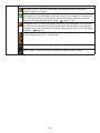
Icons
Filter sign If at least one air conditioner in a block or group needs fi lter maintenance, this
indicator lights up. When this happens, clean the fi lters.
Maintenance
Indicator
When the maintenance indicator is lit for at least one air conditioner in a block or group,
the maintenance indicator is displayed. If the maintenance indicators are off on all
units, the maintenance indicator turns off. Contact your dealer if this indicator is on.
(Gray)
Inspection, Inspection 1, Inspection 2
(Yellow)
Backup operation (Inspection 3)
Scheduling
This shows the group that is the target of the current day’s schedule.
Air direction This shows the status of louver operation.
Swinging (AUTO)
Position 1 (STOP 1)
Position 2 (STOP 2)
Position 3 (STOP 3)
Position 4 (STOP 4)

– 13 –
Unit states The unit status is shown by fi gures.
Error stop (One or more units have been stopped because of malfunction.)
Please contact your dealer.
Demand (The external signal is inputted to the demand terminal.)
The target unit’s set temperature shifts by 2 deg C or the target unit will switch to
fan mode and remote controller operations are prohibited. When the external
signal is cancelled, the setting will return. page 34, 71
Emergency stop (The external signal is inputted to the emergency stop terminal.)
All units stop and operations are prohibited. When the emergency stop signal is
cancelled, the remote controller lock/unlock setting will return but the units remain
stopped.
page 71
Accounting period time (This shows the accounting period time 2, 3 or 4. The icon
of accounting period time 1 is not shown. )
Energy saving (This shows the group that is the target for energy saving.)
Silent mode (This shows the group that is the target for silent mode.)

– 14 –
Operation
Attention
A static electric discharge to the unit could cause a break-down.
Before performing operations, touch a grounded metal object and discharge any static
electricity.
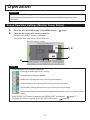
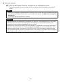
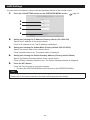
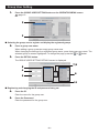
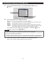
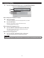
Group Operation Settings (Monitor Group Status)
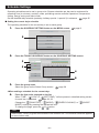
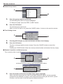
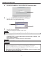
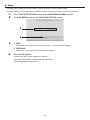
1. Press the ALL BLOCKS button on the MENU screen. page 9
2. Press the block you wish to set or monitor.
The BLOCK LAYOUT screen is displayed.
The group name and status can be observed.
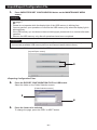
[BLOCK LAYOUT screen]
3, 5
6
4
Note
• Icons displayed have following meanings.
: Running (at least one unit is running)
: Stopped (all units have stopped)
: Malfunction (at least one unit is not in good condition)
: Communication error (at least one unit can not communicate)
: Home leave running (at least one unit is running for home leave)
: Home leave stopped (all units have stopped and at least one unit’s status is home
leave)
• If the GROUP LIST button is pressed, the GROUP LIST is displayed.
page 17
• To display the units in a group, press the UNIT LIST button.
page 30

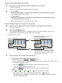
– 15 –
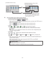
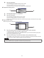
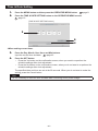
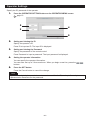
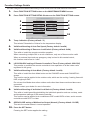
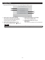
<When running and stopping each group>
3. Press the icon of the group for which settings are to be made.
The frame turns red.
When you want to cancel, please press the icon again.
4. ● To run units
Press the RUN button, and press the Yes button on the confi rmation screen.
The selected group starts running.
● To stop units
Press the STOP button, and press the Yes button on the confi rmation screen.
The selected group stops running.
When you do not want to set, press the No button.
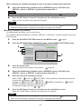
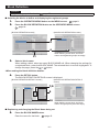
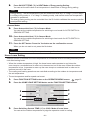
<When making settings and changes on each group>
5. Press the icon of the group for which settings or changes are to be made.
The frame turns red.
6. Press the CHANGE button.
The CHANGE GROUP screen is displayed. When the screen changes, no items are
selected. Set only the items that are to be set or changed.
This function can be applied to the indoor
units, which are the model KXE4 or later,
and to the wired remote controller, which
is the model RC-E1 or later.
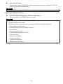
[CHANGE GROUP screen]
(Individual lock/unlock settings valid in
FUNCTION SETTING)
8
7
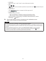
7. Press the button for the item to set or change.
•
RUN/STOP/HOME LEAVE ON/HOME LEAVE OFF
Press the RUN, STOP,
or button.
– When the RUN button is selected, the operation starts, and when the STOP button is
selected, the operation stops.
– When the
button is selected, Home leave operation starts.
* MODE and SET TEMP. cannot be set.
– When the
button is selected, Home leave operation stops.
•
MODE
Select Auto, Cool, Dry, Fan or Heat by pressing the button.
– Auto Mode can be valid in the FUNCTION SETTING. page 68
This function can be applied to the indoor units, which are the cooling/heating free
multi KXR, single split PAC.

– 16 –
•
SET TEMP.
Press or .
page 50 (TEMPERATURE RANGE SETTING)
•
FAN
Select (Powerful), (High), (Medium), (Low), or (AUTO), and press the
button.
– When using automatic mode, valid the AUTO FAN on the FUNCTION SETTING.
– When using powerful mode, select 4-speed for FAN TYPE on the GROUP
DEFINITION DETAILS screen.
(Powerful mode)
Operates with the maximum fan speed.
It is suitable for heating or cooling the entire room thoroughly.
•
Air direction
Select Auto, stop 1, stop 2, stop 3 or stop 4 and press the button.
•
Lock
Press or .
If is pressed, remote controller operations are permitted, and if is pressed, they are
prohibited.
•
FILTER RESET
If the
button is pressed, the fi lter sign turns off.
•
Energy Saving
Press the ON or OFF button.
– When the ON button is selected, energy saving operation starts.
– When the OFF button is selected, energy saving operation stops.
Use this operation to save energy.
A unit shifts its set temperature by outside
temperature. page 51
8. Press the SET button. Press the Yes button on the confi rmation screen.
When you do not want to set or change, press the No button.
Note
• If the BACK button is pressed, it returns to the previous screen.
• If individual lock/unlock is valid in the MAINTENANCE MENU, it is possible to set the remote
controller operations to permit or prohibit each item such as run/stop, mode and temperature
setting.
• When individual lock/unlock are valid in the MAINTENANCE MENU, remote controller
operations are prohibited if run/stop, mode and temperature setting are all
. (Some
functions, such as reset of the fi lter sign have been permitted.)
• RUN is indicated when at least one unit is running.
Malfunctions are indicated when at least one unit is not in good condition.
STOP is indicated when all the units have stopped.
HOME LEAVE is indicated when at least one unit is set for home leave.
• Operating mode, temperature setting, room temperature, fan speed and air direction show
the state of the representative unit.
• Groups that have the current day’s schedule settings show
.
•
icon is displayed when at least one unit needs cleaning fi lter.
•
icon is displayed when at least one unit needs maintenance.
•
icon is displayed when the group is the target for energy saving.
•
icon is displayed when the group is the target for silent mode.

– 17 –
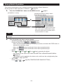
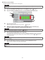
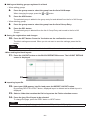
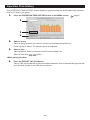
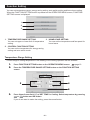
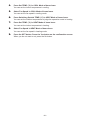
■
The following method can also be used to set and change operations on each group.
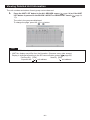
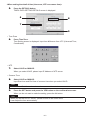
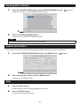
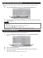
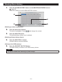
<When making settings or changes in the GROUP LIST screen>
1. Press the GROUP LIST button in the BLOCK LAYOUT screen. page 14
[GROUP LIST screen]
3
2
2.
Press the name of the group for which settings or changes are to be made.
The group name is reverse highlighted. To change the page, press the
or button.
3. Press the CHANGE button.
The CHANGE GROUP screen is displayed. Make the settings or changes.
page 15
Note
• If the BACK button is pressed, it returns to the previous screen.
• RUN is indicated when at least one unit is running. Malfunctions are indicated when at least
one unit is not in good condition. STOP is indicated when all the units have stopped.
HOME LEAVE is indicated when at least one unit is set for home leave.
Operating mode, temperature setting, room temperature, fan speed and air direction show
the state of the representative unit.
• Groups that have the current day’s schedule settings show
.
•
icon is displayed when at least one unit needs cleaning fi lter.
•
icon is displayed when at least one unit needs maintenance.
•
icon is displayed when the group is the target for energy saving.
•
icon is displayed when the group is the target for silent mode.
• The ones which are surrounded by red frames are the items which operations from the
remote controller are prohibited in the group settings.
•
If the BLOCK LAYOUT button is pressed, the BLOCK LAYOUT screen is displayed.
page 14

– 18 –
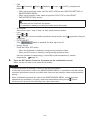
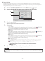
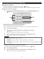
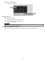
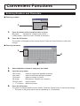
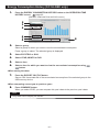
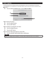
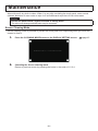
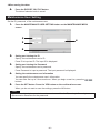
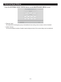
<When making settings or changes in the ALL GROUPS screen>
1. Press the ALL GROUPS button on the MENU. page 9
[ALL GROUPS screen]
3
2
2.
Press the name for the group to set or change.
The group name is reverse highlighted.
When the screen switches, the previously selected group name is selected. To change the
page, press the
or button. By pressing the or button, the page moves to the fi rst
page or last page.
3. Press the CHANGE button.
The CHANGE GROUP screen is displayed. Make the settings or changes.
page 15
Note
• To display the units in a group, press the UNIT LIST button.
page 30
• To show all blocks, press the ALL BLOCKS button.
page 11
• The ones which are surrounded by red frames are the items which operations from the
remote controller are prohibited in the group settings.
• If the MENU button is pressed, the MENU screen is displayed.
page 9

– 19 –
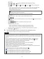
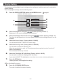
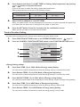
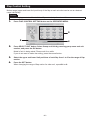
Multiple Groups Operation Settings
This section shows how to operate multiple groups in the same block.
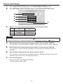
1. Press the ALL BLOCKS button on the MENU. page 9
2. Press the block you wish to set.
The BLOCK LAYOUT screen is displayed.
[BLOCK LAYOUT screen]
3, 5
6
4
<When running and stopping multiple groups>
3. Press the icons of the groups for which settings are to be made (multiple groups can
be selected).
The frame turns red.
When you want to cancel, please press the icon again.
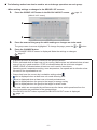
4. ● To run units
Press the RUN button, and press the Yes button on the confi rmation screen.
The selected groups start running.
● To stop units
Press the STOP button, and press the Yes button on the confi rmation screen.
The selected groups stop running.
When you do not want to set, press the No button.
<When making settings and changes on multiple groups>
5. Press the icons of the groups for which settings or changes are to be made (multiple
groups can be selected).
The frame turns red.
When you want to cancel, please press the icon again.
6. Press the CHANGE button.
The screen to change groups is displayed. When the screen changes, no items are
selected. Set only the items that are to be set or changed.
Page is loading ...
Page is loading ...
Page is loading ...
Page is loading ...
Page is loading ...
Page is loading ...
Page is loading ...
Page is loading ...
Page is loading ...
Page is loading ...
Page is loading ...
Page is loading ...
Page is loading ...
Page is loading ...
Page is loading ...
Page is loading ...
Page is loading ...
Page is loading ...
Page is loading ...
Page is loading ...
Page is loading ...
Page is loading ...
Page is loading ...
Page is loading ...
Page is loading ...
Page is loading ...
Page is loading ...
Page is loading ...
Page is loading ...
Page is loading ...
Page is loading ...
Page is loading ...
Page is loading ...
Page is loading ...
Page is loading ...
Page is loading ...
Page is loading ...
Page is loading ...
Page is loading ...
Page is loading ...
Page is loading ...
Page is loading ...
Page is loading ...
Page is loading ...
Page is loading ...
Page is loading ...
Page is loading ...
Page is loading ...
Page is loading ...
Page is loading ...
Page is loading ...
Page is loading ...
Page is loading ...
Page is loading ...
Page is loading ...
Page is loading ...
Page is loading ...
Page is loading ...
Page is loading ...
Page is loading ...
Page is loading ...
-
 1
1
-
 2
2
-
 3
3
-
 4
4
-
 5
5
-
 6
6
-
 7
7
-
 8
8
-
 9
9
-
 10
10
-
 11
11
-
 12
12
-
 13
13
-
 14
14
-
 15
15
-
 16
16
-
 17
17
-
 18
18
-
 19
19
-
 20
20
-
 21
21
-
 22
22
-
 23
23
-
 24
24
-
 25
25
-
 26
26
-
 27
27
-
 28
28
-
 29
29
-
 30
30
-
 31
31
-
 32
32
-
 33
33
-
 34
34
-
 35
35
-
 36
36
-
 37
37
-
 38
38
-
 39
39
-
 40
40
-
 41
41
-
 42
42
-
 43
43
-
 44
44
-
 45
45
-
 46
46
-
 47
47
-
 48
48
-
 49
49
-
 50
50
-
 51
51
-
 52
52
-
 53
53
-
 54
54
-
 55
55
-
 56
56
-
 57
57
-
 58
58
-
 59
59
-
 60
60
-
 61
61
-
 62
62
-
 63
63
-
 64
64
-
 65
65
-
 66
66
-
 67
67
-
 68
68
-
 69
69
-
 70
70
-
 71
71
-
 72
72
-
 73
73
-
 74
74
-
 75
75
-
 76
76
-
 77
77
-
 78
78
-
 79
79
-
 80
80
-
 81
81


Mitsubishi Heavy Industries SC-SL4-BE User manual
- Category
- Split-system air conditioners
- Type
- User manual
- This manual is also suitable for
Ask a question and I''ll find the answer in the document
Finding information in a document is now easier with AI
Related papers
-
Mitsubishi Heavy Industries SC-SL4-BE User manual
-
Mitsubishi Heavy Industries SC-SL4-BE/1 User manual
-
-
Mitsubishi Heavy Industries SC-SL4-AE/B Web monitoring User manual
-
Mitsubishi Heavy Industries SC-WBGW256 User manual
-
-
Mitsubishi Heavy Industries RC-EX3 Reference guide
-
-
-
Other documents
-
Samsung MWR-WS01 User manual
-
Panasonic CZ-64ESMC2 Owner's manual
-
-
-
Fujitsu UTY-DTGY Operating instructions
-
-
Sinclair CCM10/E User manual
-
Mitsubishi TG-2000A User manual
-
Mitsubishi Electric GB-50A User manual
-
York VRF Central Station Controller User manual