Page is loading ...

GE Consumer & Industrial
Appliances
I
n
s
t
a
l
l
a
t
i
o
n
I
n
s
t
r
u
c
t
i
o
n
s
Junction Box Cov
er
Suppl
ied Parts:
#10
Hex-Head Screw 1/2"
Long
Junct
ion Box Cover
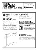
Within this user bag, you will find a junction
box cover and a #10 hex head screw used
to attach the junction box cover to the
bottom bracket or front brace (depending
on the model). The #10 hex-head screw
is packaged in a small bag within the
user bag. Use these parts when making
electrical
connections.
© 200
6
General Electric Company
Pub. No.
49-55020
Part
No
.
1
65D4700P340
ND
0
6
C
-1
6
90
(4/06)
SPECIFICATIONS SUBJECT TO CHANGE WITHOUT NOTICE
#282 French
THE JUNCTION BOX COVER AND SCREW
MUST BE USED DURING THE ELECTRICAL
CONNECTION STEPS TO AVOID THE RISK OF
FIRE OR ELECTRIC SHOCK. SEE INSTALLATION
INSTRUCTIONS.
WARNING

Pub. No. 31-30524
SPECIFICATIONS SUBJECT TO CHANGE WITHOUT NOTICE
Installation instructions
for your new
• Before you begin—Read these instructions completely and carefully.
• IMPORTANT–Save these instructions for local inspector’s use.
• IMPORTANT–OBSERVE ALL GOVERNING CODES AND ORDINANCES.
• Note to Installer–Be sure to leave these instructions with the Consumer.
• Note to Consumer–Keep these instructions with your Owners Manual for future reference.
Spacemaker™
Dishwasher
If you have a question concerning the installation of this
product, call the GE Answer Center
Consumer Information
Service at 800.626.2000, 24 hours a day, 7 days a week.
If you received a damaged dishwasher,
you should immediately contact your
dealer or builder.
Installation of this dishwasher requires basic mechanical and
electrical skills. Proper installation is the responsibility of the
installer. Product failure due to improper installation is not
covered under the GE Appliance Warranty. See the back cover
of the Owners Manual for warranty information.
The dishwasher MUST be installed to allow for future removal
from the enclosure if service is required.
MATERIALS YOU WILL NEED:
Materials required:
l 90° elbow
(3/8" NPT external thread on one end and
opposite end sized to fit water supply)
l Thread seal tape
l UL Listed Wire nuts (3)
For new installations only:
l Air gap for drain hose, if required
l Waste tee for house plumbing, if applicable
l Electrical cable or power cord, if applicable
l Screw type hose clamps
l Strain relief for electrical connection
l Hand shut-off valve (recommended)
l Water line 3/8" min. copper or 1/2" min. plastic
l Coupler for extending drain line, if applicable
Electrical Cable
or Power Cord
90° Elbow
Strain Relief
Hot Water Line
Thread Seal
Tape
Screw Type Clamps
Wire Nuts
Air
Gap
Waste
Tee
Shut-Off
Valve
Flashlight
Flat Blade Screwdriver
Drill
and Bits
Measuring Tape
Level
Phillips Head
Screwdriver
Tubing
Cutter
Square
Hole
Saw Set
TOOLS YOU WILL NEED:
Tools required:
l Phillips head and flat blade screwdrivers
l Adjustable wrench (6")
l Level
l Carpenters square
l Measuring tape
l Safety glasses
l Flashlight
For new installations only:
l Tubing cutter
l Drill and appropriate bits
l Hole saw set
Adjustable
Wrench
Safety Glasses
DWG. NO. 206C1559P064
(N.D. 679) 8/00
CAUTION:
PARTS SUPPLIED FOR INSTALLATION:
l Two Phillips head countertop mounting screws taped to dishwasher
Coupler
Figure V
Step 18 Replace access panel and toekick
Refer to Figure V. Place the toekick against the legs of the
dishwasher. Align the access panel to the dishwasher and
tighten the two access panel screws. Align the toekick and
make sure the bottom edge is against the floor. Insert and
tighten the two toekick attachment screws, making sure the
bottom edge of the toekick stays in contact with the floor.
INSTALLATION INSTRUCTIONS:
continued
Attachment Screws
Access Panel
Tighten 2
Access Panel Screws
T
oekick
Step 19 Literature
l Be sure to leave complete literature package and installa-
tion instructions with consumer.

PREPARE DISHWASHER ENCLOSURE AND SINK LOCATION
2
3
PREPARE ELECTRICAL WIRING
ELECTRICAL REQUIREMENTS:
• This appliance must be supplied with 120V, 60 Hz., and connected
to an individual, properly grounded branch circuit, protected by a
15 or 20 ampere circuit breaker or time delay fuse.
• Wiring must be 2 wire with ground.
• If the electrical supply provided does not meet the above
requirements, call a licensed electrician before proceeding.
GROUNDING INSTRUCTION
This appliance must be connected to a grounded metal, permanent
wiring system, or an equipment-grounding conductor must be run
with the circuit conductors and be connected to the equipment-
grounding terminal or lead on the appliance.
THE IMPROPER CONNECTION OF THE EQUIPMENT-
GROUNDING CONDUCTOR CAN RESULT IN A RISK
OF ELECTRIC SHOCK. CHECK WITH A QUALIFIED ELECTRICIAN
OR SERVICE REPRESENTATIVE IF YOU ARE IN DOUBT WHETHER
THE APPLIANCE IS PROPERLY GROUNDED.
CABINET PREPARATION & WIRE ROUTING
• Wiring may enter from either side, the rear, or from the floor
within the shaded area shown in Figure E.
Figure E
FOR PERSONAL SAFETY: REMOVE HOUSE FUSE OR OPEN
CIRCUIT BREAKER BEFORE BEGINNING INSTALLATION.
DO NOT USE AN EXTENSION CORD OR ADAPTER PLUG WITH THIS
APPLIANCE.
WARNING
WARNING
Figure A
Figure B
• Water line to sink faucet and drain from sink can be run
through Area “A.”
• Hot water line to dishwasher is installed in Area “B.”
• Garbage disposer, water lines to faucet, trap, waste air
gap and water shut-off valve are installed in a 12“ wide
cabinet, Area “C”.
• Sink opening for garbage disposer must be dimensioned as
shown in Area “C.” This will provide clearance for disposer
and plumbing in cabinet “C” when using either single or
double bowl sink.
5"
White
18"
6"
5"
4"4"
24"
from Wall
3"
from
Cabinet
Alternate
Receptacle
Location
Ground
Black
1-1/2" Dia. Hole (Max.)
18"
6"
6"
Receptacle
Location
Area
PREPARE CABINET CUTOUT FOR SINK:
1. This dishwasher is designed to fit into a minimum width and
depth of 24".
2. This dishwasher fits under a special sink bowl (either double
or single) with a depth of 6" or less in a 1-1/2" countertop.
Note: Dishwasher is not provided with complete enclosure.
Enclosure for sides, top, bottom, and back, must be
provided by installer at time of installation.
Note: A gap between the dishwasher tub front flange and the
front of the base cabinet may result due to either the
cabinet being less than 24" deep or the sink bowl not
being installed to specifications.
If the gap is more than 3/4", the sink bowl must be
relocated to meet specified dimensions.
Dishwasher
Side View
11-3/4" Max.
Plumbing
4"
Max.
34-1/4"
1/4"
+
_
10-1/4" MAX.
PLUMBING
DEPTH
1" Max. To
Sink Flange
20-1/2" Max.
Sink Bowl
11" Min.
Drain
6" Max.
3/4" Min.
1-1/4"
Min. I.R.
24" Min.
Cabinet
Wall
B
A
Countertop: 1-1/2" Min. Thick
10-1/4"
Max.
Area "A"
Area "B"
Area "C"
Front View
7-1/2"
Toe
Kick
Area
Floor
24"
12"
Min.
6" Max.
Cabinet Side
Adjacent to D/W
Sink
Installation
Cutout
8" X 20"
Adjacent Cabinet
Rear Cutout
12"
3-1/4"
12-1/2"
5"
5"
Dishwasher
Tub
Front
Flange
20-1/2" Max.
Sink Bowl
24" Min.
Cabinet
Wall
Gap
DRAIN REQUIREMENTS
• Follow local codes and ordinances.
• Dishwasher drain hose must not exceed 10 feet in length for
proper drainage.
• Dishwasher must be connected to waste line with an air gap
(not supplied) or 32" minimum, high drain loop depending on
local codes and ordinances to prevent back flow into the
dishwasher.
• Air gap must be used if waste tee or disposer connection is
less than 18 inches above floor to prevent siphoning.
DRAIN PREPARATION
The type of drain installation depends on answers to the
following questions:
l Do local codes or ordinances require an air gap?
l Will waste tee or disposer connection be less than 18" above
floor?
l Will installation have a drain loop less than 32" above floor?
If the answer to ANY of the 3 questions above is YES, Method 1
MUST be used. Otherwise either Method 1 or Method 2 may be
used. Figure C or Figure D.
METHOD 1–Air Gap with Waste Tee or Disposer
Install waste tee or disposer and air gap according to
manufacturer’s instructions.
CABINET PREPARATION
Drill 1-1/2" inch diameter hole in the cabinet wall within the
shaded area shown in Figure A for the drain hose. Make sure
there are no sharp edges. Drain hose will be passed through
this hole and connected to the drain in a later step.
Disposer Installation
METHOD 2–High Drain with Waste Tee or Disposer
Provide a method to attach drain hose to underside of
countertop. Attachment will be made in a later step.
Waste Tee Installation
Figure C
Waste Tee Installation Disposer Installation
Figure D
32"
Min.
18"
Min.
32"
Min.
18"
Min.
• Cut hole 1-1/2" max. dia. within the shaded area to admit the
electrical cable or power cord. The hole must be free of
sharp edges. If the cabinet wall partition is metal, the edge of
the hole must be covered with a rubber protector.
ELECTRICAL CONNECTIONS TO DISHWASHER
Electrical connection is on right side of dishwasher.
• For cable direct connections the cable must be routed as
shown in Figure E. Cable must extend a minimum of 24" from
the rear wall.
• For power cord connections, install a 3-prong grounding type
receptacle in the rear wall of sink cabinet next to the
dishwasher. The receptacle should be installed at least
6", but not more than 18", from the cabinet opening for
dishwasher.
CAUTION
An air gap MUST BE USED if the drain hose is connected to waste tee or
disposer lower than 18" above the floor level. Failure to provide the proper
drain connection height with air gap or 32" minimum, high drain loop will
result in improper draining of the dishwasher which may cause damage.
PREPARE DRAIN PLUMBING

5
4
INSTALLATION INSTRUCTIONS:
INSTALLATION INSTRUCTIONS:
Step 7 Position water line and power supply
Position the water supply line and house wiring on the floor of
the opening to avoid interference with base of dishwasher and
components under dishwasher.
continued
If you need help with any of the following steps, call the
GE Answer Center
Consumer Information Service, 800.626.2000
CAUTION
Do not remove the wood base until you are ready to install
the dishwasher. The dishwasher will tip over when the door
is opened.
Step 8 Insert drain hose through cabinet
Upright dishwasher and position in front of the cabinet
opening. Insert the drain hose into the hole previously drilled in
the cabinet wall. If a power cord is used, guide the end
through a separate hole cut for the electrical cord.
Power cord should be routed directly to the rear of junction box
avoiding contact with spring or other dishwasher components.
Step 4 Remove access panel and toekick
Remove the two screws below the access panel and set aside
for reuse. Remove access panel by backing out the two screws
located between the door and access panel. These screws are
secured to access panel with plastic retainers.
Figure I
Figure L
Step 2 Remove leveling legs and wood base.
Move the dishwasher close to the cabinet
and lay it on its back. Remove the four leveling
legs with an adjustable wrench. Remove
and discard the wood base. Do not “Kick”
wood base off, damage will occur.
Step 3 Install leveling legs
Screw leveling legs back into the dishwasher
frame. The legs should extend approximately
3/4" away from the frame.
Figure M
Step 8A
Install Trim Pieces (on some models)
• Press the trim onto the tub flange on each side of the dish-
washer. Start even with the top edge and press in as you
move to the bottom.
• Press trim piece onto top dishwasher flange.
• Open and close the door to check that trim does not bind.
For power cord installation only. Skip this step if dishwasher
will be directly wired.
Remove the junction box
cover and install strain
relief. The power cord
and connections must
comply with the National
Electrical Code, Section
422 and/or local codes
and ordinances. The cord
must be no longer than
6 ft. from the junction
box to the receptacle.
Locate the three dish-
washer wires (white,
black and green) with
the stripped ends. Using UL Listed wire nuts of appropriate size,
connect incoming white to white, black to black, and incoming
ground to green wire. Replace the junction box cover. Check
that wires are not pinched under cover.
Step 5 Install power cord (when used)
Figure J
Step 6 Install 90° elbow
Install the 90° elbow
fitting to the water
valve using thread seal
tape on the threads.
The water valve
requires 3/8" NPT
fitting with external
threads. The opposite
end should fit water
supply line. Position the
end of the elbow to face
the rear of the dishwasher.
Do not bend the dishwasher
frame when installing the 90° elbow fitting to the water
valve as this could cause the door spring to come in
contact with the fill hose.
Figure K
Step 1
Check door balance before wood base is removed
Locate the 2 Phillips head countertop mounting screws
wrapped with yellow tape and stuck to the top or side of the
dishwasher. Set aside for use in Step 12.
Check door balance by opening and closing door. If necessary
latch door and adjust one or both springs before the wood
base is removed.
Back Out
2 Screws
Access Panel
Toekick
Remove
2
Screws
Water
Line
Power
Supply
Step 9
Slide dishwasher into cabinet
Slide the dishwasher into the opening a few inches at a time.
As you proceed, pull the drain hose through the opening and
under the sink. Make sure drain hose is not kinked under
dishwasher. Check to be sure there is no interference with
water line and wiring.
DO NOT PUSH
AGAINST FRONT
DOOR PANEL
WITH YOUR
KNEE. Damage to
the door panel
will occur.
Figure N
Note: Tub trim is located in
dishwasher upper rack.
Figure G
Figure H
Figure GG
Moving Spring Hook to Rear Hole
Increases Spring Tension.
90° Elbow
Thread
Seal
Tape
White
Neutral
Ground
Black
Live
Note: Check That Harness Leads Are
Threaded Thru Small Hole in Bracket
More Tension
Less Tension
Insert Spring Hook
Through Inside of Frame
Water Line
Power
Supply
Power
Cord
(if used)
Approx.
3/4"
PREPARE HOT WATER LINE
1. The hot water line may enter from either side, the rear or from
the floor within the shaded area shown in Figure F.
2. Cut a hole approximately 1-1/2" dia. within the shaded area to
admit the line.
3. Turn off the water supply.
4. Install a hand shut-off valve in the supply line in an accessible
location, such as under the sink. (The shut-off valve is optional,
but recommended and may be required by local codes.)
5. Water connection is on left side of dishwasher. Install the hot
water inlet line, using no less than 3/8" O.D. copper tubing or
1/2" O.D. plastic tubing. Route line as shown in Figure F. Extend
the water line forward at least 19" from rear wall.
6. Adjust the water heater to deliver water between the
temperatures of 120°F and 150°F.
7. Flush water line to clean out debris.
8. The water pressure of the hot water supply line must be
20-120 PSI.
Figure F
5"
5"
6"
Cabinet Face
Shut-off
Valve
2" From Floor
19" From Wall
2"
From
Cabinet
1-1/2" Dia.
Hole
Hot
4"
4"

6
INSTALLATION INSTRUCTIONS:
continued
INSTALLATION INSTRUCTIONS:
continued
Step 14 Connect drain line
Follow all local codes and ordinances.
DRAIN LINE PREPARATION
The molded end is designed to fit 5/8", 3/4" or 1" diameter
connections to the air gap, waste tee or disposer. Cut on
premarked line as required for your installation as illustrated
in Figure R.
Note: DO NOT CUT CORRUGATED PORTION OF HOSE.
If the location requires a longer drain hose, add up to 42" of
length to the factory installed hose. Use 5/8" or 7/8" inside
diameter hose and a short section of copper water pipe of
appropriate length and diameter to connect the two hose ends.
Secure connection with appropriate clamps (not supplied).
Note: TOTAL DRAIN HOSE LENGTH MUST NOT EXCEED
10 FEET FOR PROPER DRAIN OPERATION.
DRAIN LINE INSTALLATION
Connect drain line to air gap, waste tee or disposer using either
Method 1 or Method 2 as previously determined. Refer to Figure
S or Figure T.
Secure connection using appropriate clamps (not supplied).
Make sure drain hose is not kinked.
Figure R
Method 1–Air gap with waste tee or disposer
Waste tee installation Disposer Installation
Figure S
Waste tee installation
Disposer Installation
Figure T
Method 2–High drain loop with waste tee or disposer
Note: BE SURE TO REMOVE DRAIN PLUG FROM DISPOSER
BEFORE ATTACHING DRAIN LINE. DISHWASHER WILL NOT
DRAIN IF PLUG IS LEFT IN PLACE.
Figure Q
Step 13 Connect water supply
Connect water supply line to 90° elbow installed in Step 6.
Open and close the door. Check to be sure door spring does not
rub against fill hose or water supply line.
Cutting Lines
1"
3/4"
5/8"
Do not cut corrugated
portion of hose
Fasten to underside
of countertop
32"
Min.
18"
Min.
Step 15 Connect power supply
Verify that power is turned off at source. If power cord is used,
plug it into the wall outlet and go to Step 16. If dishwasher is to
be directly wired to house wiring, continue with this step.
Remove junction box cover.
Secure the power supply cable to the back of the junction box
with a strain relief (not supplied).
If house wiring is not 2-wire with a ground wire,
a ground must be provided by the installer.
When house wiring is aluminum, be sure to use U.L. Listed
anti-oxidant compound and aluminum-to-copper connectors.
Figure U
WARNING
7
Min.
Fasten to underside
of countertop
Locate the three dishwasher wires (white, black, and green)
with the stripped ends. Insert the three wires through the small
hole in the junction box bracket. Using wire nuts of appropriate
size, connect incoming ground to green wire, white to white
and black to black, as shown in Figure U. Replace the junction
box cover. Check to make sure that wires are not pinched under
junction box cover.
Important: When opening and
closing the door, the door
spring should not touch the fill
hose. If it does, bend water
valve bracket slightly to
provide clearance between
the spring and the fill hose.
90° Elbow
Hot Water
Supply Line
Fill Hose
Water Valve Bracket
White
Neutral
Ground
Black
Live
Note: Check That
Harness Leads Are
Threaded Thru Small
Hole in Bracket
Step 10 Align water and electrical lines
Route the water line and electrical
supply to their connection
locations under the dishwasher.
Do not connect water and
electrical in this step.
Step 12
Position dishwasher and fasten to cabinet
Open the door and position the dishwasher tub flange 3/4" from
the cabinet opening. Fasten the dishwasher to the underside of
the countertop, using the 2 Phillips screws provided in Step 1.
Be sure screws are driven straight and flush to avoid interfer-
ence with door operation. See Figure P.
Step 11 Level dishwasher
Level the dishwasher by adjusting the four
leveling legs individually for correct align-
ment. See Figure O.
Dishwasher should be level left to right and
front to back for proper dish rack operation
and dishwasher performance. Dishwasher
door should be in alignment with adjacent
cabinets. See Figure P.
Figure O
Important:
Make sure that
dishwasher is
centered in the
opening and
there is no
interference with
cabinets when
opening or closing
the door. Interfer-
ence may cause a
water leak when
dishwasher is in
operation.
3/4"
Rear View
Water
Electric
Figure P
l Pull lower rack about half way out. Check to be sure it does
not roll back into dishwasher or further out. If it does, relevel
dishwasher.
l Turn on water supply.
l Check for plumbing leaks. Tighten connections if necessary.
l Check that door spring does not contact water line, fill hose,
wiring or dishwasher components.
l Turn on the hot water faucet at the sink and verify water
temperature. Water going to dishwasher must be between
the temperatures of 120°F and 150°F.
Step 16 Pre-test check list
l Check to be sure power is off.
l Open dishwasher door and remove all foam and cardboard
packaging.
l Remove literature package with Use & Care manual.
l Read the Use & Care manual to familiarize yourself with the
operation of the dishwasher.
l Add two quarts of water to the bottom of the dishwasher to
lubricate the pump seal.
l Remove the protective film if present from the control
panel, access panel and door panel.
l Check to be sure that wiring is secure under the dish-
washer, and not pinched or in contact with door springs or
other dishwasher components.
Step 17 Dishwasher wet test check list
l Turn on power supply.
l Latch door.
l Select normal cycle on push-button or electronic models.
l On dial models, turn control dial just enough to start
dishwasher. Be careful not to turn the dial past the first
water fill. On electronic models, push start pad.
l Check to be sure that water enters the dishwasher. This
could take up to 4 minutes.
If water does not enter the dishwasher, check to be sure
that water is turned on.
l Check for leaks under the dishwasher. If a leak is found,
turn off power supply, tighten connections and restore
power.
l Check for leaks around the door. A leak around the door
could be caused by dishwasher door rubbing or hitting
against adjacent cabinetry. Reposition the dishwasher if
necessary.
l The dishwasher will drain about 5 minutes after the first fill.
Check drain lines. If leaks are found, turn off power, correct
as necessary and restore power.
l Open dishwasher door and make sure most of the water has
drained. If not, check that disposer plug has been removed
and/or air gap is not plugged.
l Let the dishwasher run through another fill and drain cycle.
Check again to be sure there are no leaks.
l At the end of the second drain, push the reset pad on
electronic models. On dial models, unlatch the door and
rotate the dial to the “OFF” position.
/