GE GLD5800L15WW Installation guide

Category
Dishwashers
Type
Installation guide
Appliances
Installation
Built-In Dishwasher
If gou have questions, call 800.GE.CARES (800.432.2737) or visit our websJte at: www.ge.com
Instructions
BEFORE YOU BEGIN
Read these instructions completelu and
carefullu.
IMPORTANT- Observe all governing codes and
ordinances.
, Note to Installer - Be sure to leave these instructions for the
consumer's and local inspector's use.
Note to Consumer - Keep these instructions with your
Owner's Manual for future reference.
, Skill Level - Installation of this dishwasher requires
basic mechanical, electrical and plumbing skills. Proper
installation is the responsibilitg of the installer. Product
failure due to improper installation is not covered under
the GEAppliance Warranty. See warrantg information.
, Completion Time - 1 to 3 Hours. New installations require
more time than replacement installations.
IM PORTANT- The dishwasherMUST
be installedtoallowforfutureremovalfromtheenclosure
if service is required.
If Uoureceived a damaged dishwasher, Uoushould
immediately contact your dealer or builder.
Optional Accessories - Seethe Owner's Manual for available
custom panel kits.
FOR YOUR SAFETY
Read and observe all CAUTIONSand WARNINGS
shown throughout these instructions. While performing
installations described in this booklet, gloves, safety glasses
or goggles should be worn.
READ CAREFULLY.
KEEP THESE INSTRUCTIONS.
imagination atwork
InstallationPreparation
PARTS SUPPLIED:
[] Two #8-18 x 5/8" Phillips special head screws,
to secure dishwasher to underside of countertop
or to side of cabinets. (Inuser bag.)
[] Side and top trim pieces on some models
[] Drain hose
[] Drain hose hanger
[] Clamp
Drain Hose
Side and Top TMm Pieces on some models
Clamp
#8 Phillips
Special Head
Screws
5/8" long
Drain Hose Hanger
MATERIALS YOU WILL NEED :
[] Ferrule, compression nut and 90° Elbow (3/8"NPT
external thread on one end, opposite end sized to fit
water supply)
[] Thread seal tape
[] UL Listed wire nuts (3)
90° Elbow, Hand
Ferrule and Shut-Off
Compression Nut Valve
Thread
Seal Tape
Wire Nuts (3)
MaterialsFor New InstallationsOnly:
[] Air gap for drain hose,if required
[] Waste tee for house plumbing, if applicable
[] Electrical cable or power cord, if applicable
[] Screw type hose clamps
[] Strain relief for electrical connection.
[] Hand shut-off valve (recommended)
[] Water line 3/8" rain. copper
[] Coupler for extending drain line,if applicable
Waste Tee
Electrical Cable
(or Power Cord, if applicable}
Screw Type
Air Gap Hose Clamps
Hot Water Line
©
Strain Relief
Coupler
TOOLS YOU WILL NEED:
[] Phillips head screwdriver
[] 1/4" and 5/16" nutdriver
[] 6" AdJustable wrench
[] Level
[] Carpenters square
[] Measuring tape
[] Safety glasses
[] Flashlight
[] Bucket to catch water when flushing the line
[] 15/16" socket (optional for skid removal)
[] Gloves
15116" Socket
For New InstallationsOnly:
[] Tubing cutter
[] Drill and appropriate bits
[] Hole saw set
Flashlight
Gloves Bucket
Level
1/4" and 5/16"
NutdMver
n6A"djustC_ble
Tubing Cutter
SafetyGlasses
Hole Saw Set
Carpenters
Square
MeasuMng Tape
InstallationPreparation
PREPARE DISHWASHER ENCLOSURE
34-1/2"1/4"
Underside of
Countertop
to Floor
ThisWallArea
must beFree
of Pipesor
wires
--5"_ t-
Figure A
_'_ 24"
/
Min.
_FloorMUST be Even
With Room Floor
Cabine
-Square
and
Plumb
oThe rough cabinet opening must be at least 24" deep, 24"
wide and approximatelu 34-1/2" high from floor to underside
of the countertop.
DRAIN REQUIREMENTS
, Follow local codes and ordinances.
, Do not exceed 10' distance to drain.
NOTE:Air gap must be used, if waste tee or disposer
connection is less than 18" above floor to prevent siphoning.
DETERMINE DRAIN METHOD
The tgpe of drain installation depends on the following
questions.
[] Do local codes or ordinances require an air gap?
[] Is waste tee less than 18" above floor?
If the answer to either question is YES,Method 2 MUST
be used.
. If the answers are NO,either method mag be used.
CABINET PREPARATION
, Drill a 1-1/2" dia. hole in the cabinet wall within the shaded
areas shown in Figure A for the drain hose connection. The
hole should be smooth with no sharp edges.
IMPORTANT-when
connecting drain line to disposer,
check to be sure that drain plug has
been removed. DISHWASHERWILL
NOTDRAINIF PLUGISLEFTIN PLACE.
4_ emove
Hopper
Plug
WARNING:
Toreduce the risk of electric shock, fire, or injuru to
persons, the installer must ensure that the dishwasher is
completel Uenclosed at the time of installation.
The dishwasher must be installed so that drain hose is no
more than 10' in length for proper drainage.
The dishwasher must be fullg enclosed on the top, sides and
back, and must not support ang part of the enclosure.
CLEARANCES: When
installed into a corner,
allow 2" rain. clearance
between dishwasher
and adjacent cabinet,
wall or other appliances.
Allow 28-3/8" min. clear-
ance from the front of
the dishwasher for door
opening. Figure B
Figure B
LCountertop
I
Dishwasher
28-3/8'
- Clearance for DoorOpening 2" Minimum
__ r_
Figure C
Method 1 - Air Gap with Waste Tee or Disposer
An air gap must be used when required bU local codes and ordi-
nances. The air gap must be installed according to manufacturer's
instructions.
Drain Hose Hanger _./'_3 Drain Hose Hunger
_ ,_
Figure D
Method 2 - "High Drain Loop" with Waste Tee or Disposer
Note: Avoid unnecessary service call charges. Always be
sure disposer drain plug has been removed before attaching
dishwasher drain hose to the disposer.
InstallationPreparation
PREPARE ELECTRICAL WIRING
FOR PERSONAL SAFETY: Remove house
fuse or open circuit breaker before
beginning installation. Do not use an
extension cord or adapter plug with this
appliance.
Electrical Requirements
, This appliance must be supplied with 120V, 60 Hz., and
connected to an individual properly grounded branch circuit,
protected by a 15 or 20 ampere circuit breaker or time delay
fuse.
, Wiring must be 2 wire with ground and rated for 75°C (176°F).
, If the electrical supply does not meet the above requirements,
call a licensed electrician before proceeding.
Grounding Instructions-Cable Direct
This appliance must be connected to a grounded metal,
permanent wiring system, or on equipment grounding
conductor must be run with the circuit conductors and be
connected to the equipment grounding terminal or lead on the
appliance.
Grounding Instructions-Power Cord Models
This appliance must be grounded. In the event of a malfunction
or breakdown, grounding will reduce the risk of electric shock
by providing a path of least resistance for electric current.
This appliance is equipped with a cord having an equipment
grounding conductor and a grounding plug. The plug must
be plugged into an appropriate outlet that is installed and
grounded in accordance with all local codes and ordinances.
The improper connection of the equip-
ment grounding conductor can result
in a risk of electric shock. Check with
a qualified electrician or service
representative if you are in doubt that
the appliance is properly grounded.
Cabinet
Figure E White
For models equipped with power cord: Do not modify the plug
provided with the appliance; if it will not fit the outlet, have a
proper outlet installed by a qualified technician.
Cabinet Preparation & Wire Routing
, Thewiring may enter the opening from either side, rear or the
floor within the shaded area.
, Cuta 1-1/2" max. dia. hole to admit the electrical cable. Cable
direct connections mag pass through the same hole as the
drain hose and hot water line,if convenient. If cabinet wall is
metal, the hole edge must be covered with a bushing.
NOTE:Power cords with plug must pass through aseparate
hole.
Electrical Connection to Dishwasher
Electrical connection is on the right front of dishwasher.
For cable direct connections the cable must be routed as
shown in Figure E.Cable must extend a minimum of 24" from
the rear wall.
For power cord connections, install a 3-prong grounding type
receptacle in the sink cabinet rearwall, 6" rain. or 18" max.
from the opening, 6" to 18" above the floor
InstallationPreparation
PREPARE HOT WATER LINE
. The line may enter from either side, rear or floor within the
shaded area shown in Figure K
o The line may pass through the same hole as the electrical
cable and drain hose. Or,cut an additional 1-1/2" dia. hole to
accommodate the water line. If power cord with plug is used,
water line must not pass through power cord hole.
I
I
d
I
i!-!/2" Di
::i Shut-'off _Hole
Valve
Hotii::::::::::
ii2"--
From
Cabinet
Cabinet Face_
Figure F
Water Line Connection
Turn off the water supply.
Install a hand shut-off valve in an accessible location, such
as under the sink. (Optional, but strongly recommended and
may be required by local codes.)
Water connection is on the left side of the dishwasher. Install
the hot water inlet line, using no less than 3/8" O.D.copper
tubing. Route the line as shown in Figure Fand extend
forward at least 19" from rear wall.
Adjust water heater for 120°F to 1S0°Ftemperature.
Flush water line to clean out debris.
The hot water supply line pressure must be 20-120 PSI.
CAUTION:
_;;_ Do not remove wood base until you are
reads to install the dishwasher The dishwasher will
tip over when the door is opened.
STEP I CHECK DOOR BALANCE
With dishwasher on the wood skid, check the door balance
by opening and closing the door.
If door drops open when released, increase spring tension. If
door closes when released, decrease tension.
Note: Increase or decrease
tension as shown. Adjust
both springs to the same
tension setting to correct
balance. Increase
Spring
Tension
Hook
Over
Spring
Tension
Correct
Incorrect
Figure G _
Tip: If door spring adjustment is necessary, check door
opening and closing. If door does not open easily or falls too
quickly, check spring cable routing. The cable is held in place
by "shoulders" on the pulley. Check to be sure cable has not
slipped over the pulley shoulders.
STEP 2 REMOVE WOOD BASE,
INSTALL LEVELING LEGS
IMPORTANT - Donotkickoffwoodbase!
Damage willoccur.
. Move the dishwasher close to the installation location and
lag it on its back.
Remove the four leveling legs on the underside of the wood
base with an adjustable
wrench or 15/16" socket.
, Discard base.
Figure H
Screw leveling legs back into the dishwasher frame,
approximately 1/8" from frame as shown.
Installation Instructions
STEP 3 REMOVE TOEKICK /_._
, Remove the _ /7//f ,//1
2 toekick screws _ I
and toekick. --__///A/o_/f_" '1
Setaside for use "_ - [.-'_--_-/
..... _ k--q_--,(/ Remove2
In b_:ep ±_. Figure, --_--_ Toekick Screws
STEP 4 INSTALL POWER CORD
Skip this step if dishwasher will be direct wired or
has a factorg installed power cord.
Use Power Cord KitWX09X70910, available for
purchase from an authorized GEAppliance Dealer.
The power cord and connections must compl9 with
the National Electrical Code, Section 422 and/or local
codes and ordinances.
, Haximum power cordlength is 6 feet.
Note: Check That Harness
Leads Are Threaded Thru Ground
/
Small Hole in Bracket /
White
Do Not
Use
Figure J
, Connect incoming power cord white (or ribbed) to dishwasher
white, block (or smooth) to block and ground to dishwasher
green wire. Use UL listed wire nuts of appropriate size.
Replace junction box cover. Be sure wires ore not pinched
under the cover.
STEP 5A INSTALL DRAIN HOSE TO
DISHWASHER DRAIN PORT
Skip this step if drain hose has been pre-installed.
In this step gou will need the drain hose set aside prior
to Step 1.
, Stand dishwasher upright.
, Remove hose clamp attached to drain hose. Placehose
clamp over the small end of the drain hose.
Tip: Prevent drain hose damage and possible leaks.
Be careful not to nick or cut the drain hose.
Push the small end of the drain hose over the drain port of
the dishwasher, see Figure L
, Hake sure hose is fullg seated on the dishwasher drain port.
, Position hose clamp against the front lip of the drain hose
and tighten clamp.
Drain Outlet Shoulder Stun
\
STEP 5 INSTALL 90 °
ELBOW
, Wrap 90° elbow with
thread seal tape.
, Install o 90° elbow onto
the water valve.
, Do not over tighten
90° elbow. Water
valve bracket could
bend or water valve
fitting could break.
, Position the end of the
elbow to face the rear
of the dishwasher.
90
Elbow
Front of Dishwasher
__/_ trercV_,tve
Thread Seal Tape
Figure K
Hint: for leek free connections:
, Insert hose ogoinst stop on pump.
, Position clamp ogoinst front lip of drain hose.
, Tighten clamp to at least 15 inch-pounds of torque.
Stop
Front Lip
of Hose
Figure M
Installation Instructions
STEP 6 POSITION WATER LINE
AND HOUSE WIRING
, Position water supply line and house wiring on the floor of the
opening to avoid interference with base of dishwasher and
components under dishwasher.
STEP 8 SLIDE DISHWASHER PARTIALLY
INTO CABINET
DO NOT PUSHAGAINST FRONTPANELWITH KNEES.
DAMAGEWILL OCCUR.
, Slide dishwasher into the opening a few inches at a time.
House _
Line Wiring
Figure N
STEP 7 INSTALL DRAIN HOSE,
THROUGH CABINET
, Position dishwasher in front of cabinet opening. Insert drain
hose into the hole in cabinet side. Ifa power cord is used,
guide the end through a separate hole.
Maximum Drain Hose
Length 10'
Insulatior
Blanket
Do Not Push Against
Front Door Panel With
Knee. Damage to The
Door Panel Will Occun
Figure P
, As you proceed, pull the drain hose through the opening
under the sink. Stop pushing when the dishwasher is a few
inches forward of adjacent cabinets.
, Make sure drain hose is not kinked under the dishwasher and
there is no interference with the water line,wiring and/or any
dishwasher component.
STEP 9 INSTALL TRIM PIECES
Skipthis step if trim is not supplied with the
dishwasher.
o Locate trim strips inside dishwasher.
, Presstrim onto the tub flange on each side. Start with the top
edge, pressing on as you move towards the bottom.
, Pressthe two top trim pieces on each side of the latch.
Open and close the door to check that trim does not bind and
does not interfere with door latch.
Hose
/
House
Wiring
Power Cord
(If Used)
Trim
Strip
Trim Strip
\
\
Figure 0
Tip: Position water line and house wiring onthe floor
to avoid interference with base of dishwasher.
Figure Q
Installation Instructions
STEP 10 PUSH DISHWASHER INTO
FINAL POSITION
Tip: Check tub insulation blanket, if equipped. It should be
positioned so it isnot "bunched up" or interfering with door
springs. Check by opening and closing dooE
o Push dishwasher into the cabinet. The edges of the
dishwasher door should be behind the cabinet frame and
evenly aligned with the front face of cabinet doors.
Carefully open and close the door to ensure the door panel is
not catching or rubbing on the cabinet frame.
Door
Fitsand _._
Swings x
Back \\
\
Behind
DoorCatches\,,
Cabinet i on CabinetFrame!
Frame_x[_ / / ,'
J_/'_\\ Incorrect Alignment
Correct will resultin
Alignment "_- door damage
Figure R
STEP 3.3.LEVEL DISHWASHER
IMPORTANT- Dishwasher must be level
forproperdishrackoperationand wash performance.
Place level on door and rack track as shown. Checkto make
sure that the dishwasher is level.
/ \
to-B %
Figure S
, Levelthe dishwasher by adjusting the four leveling legs
individually.
* If adjustment to the right rear leveling leg is required, loosen
junction box bracket screw (through the access hole) and
rotate bracket clockwise to provide additional access.
Tip: Pull lower rack out, about halfway. Checkto be
sure the rack does not roll forward or back into
dishwasher. If the rack rolls in either direction, the
dishwasher must be leveled again.
. If door hits tub, the dishwasher is not installed correctly.
Adjust leveling legs to align door to tub.
LTurn LegsCaF/
to Adjust_
Figure T
Installation Instructions
STEP 12 POSITION DISHWASHER, SECURE
TO COUNTERTOP OR CABINET
In this step you will need the 2 Phillips speciol head
screws set oside prior to Step 1.
The dishwasher must be secured to the countertop or
the cabinet sides. Fordishwashers which require side mounting
brackets, order part GPF65from your authorized GEAppliance
Dealer.
Tip: Prevent door panel and control panel damage.
Dishwasher must be positioned so the front panel and
control panel do not contact the adjacent cabinets or
countertop. Mounting screws must be driven straight
and flush. Protruding screw heads could scratch the
door panel or control panel and interfere with door
operation.
Secure dishwasher to underside of wood countertop.
o Recheck alignment of the dishwasher in the cabinet. Refer to
Step !0, Figure Rand Step 11. Door panel
and/or control panel must not hit cabinets or countertop.
o Fasten the dishwasher to the underside of the countertop
with the 2 Phillips special head screws provided. Refer to
Figure U.Make certain screws are driven straight and flush to
prevent panel damage.
Brackets
Wood Countertop
/
A
Figure U
STEP 13 CONNECT WATER SUPPLY
Connect water supply line to g0° elbow.
Slide compression nut, then ferrule over end of
water line.
Insert water line into 90 ° elbow.
Slide ferrule against elbow and secure with compression nut.
IMPORTANT- Checkto be sure that door
spring does not rub or contact the fill hose or water supply line.
Test by opening and closing the door. Re-route the lines if a
rubbing noise or interference occurs.
...........Compression
Nut
Ferrule
Hot Water
_--_90°E!b°w Supply Line
Door Spring
Figure V
Installation Instructions
STEP 14 CONNECT DRAIN LINE
FOLLOW ALL LOCALCODESAND ORDINANCES.
Identify the type of drain hose you have. The molded
end of the drain hose will fit 5/8" through 1"diameter
inlet ports on the air gap, waste tee or disposer.
o Determine size of inlet port
Cut drain hose connector on the marked line, if required, to fit
the inlet port.
Cutting Line
IMPORTANT: Do not cut corrugated
portion of hose
Figure W
, If a longer drain hose isrequired, add up to 42" of length for
a total of !0' to the factory installed hose. Use 5/8" or 7/8"
inside diameter hose and a coupler to connect the two hose
ends. Secure the connection with hose clamps.
Hose Clamp
Hose Clamp
Coupler
Figure ×
Secure the drain hose to the air gap, waste tee or disposer
with clamps.
NOTE:TOTAL DRAIN HOSE LENGTH MUST NOT EXCEED !0 FEET
FOR PROPER DRAIN OPERATION.
DRAIN LINE INSTALLATION
, Connect drain line to air gap, waste tee or disposer
using either previously determined method.
Method 1 - Air gap with waste tee or disposer
Waste Tee Installation
Disposer Installation
Figure V
Method 2 - "High drain loop" with waste tee or disposer
Fasten to Underside of Countertop
with Hanger Supplied
Waste Tee Installation
Fasten to Underside of Countertop
with Hanger Supplied
Disposer Installation
Figure Z
IMPORTANT - When connecting drain lineto
disposer, check to be sure that drain plug has been removed.
DISHWASHERWILL NOTDRAINIF PLUGISLEFTIN PLACE.
Remove
Hopper
Plug
TIP:Avoid unnecessary service call charges. Always be sure
disposer drain plug has been removed before attaching
dishwasher drain hose to the disposer.
lo
Installation Instructions
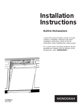
STEP 15 CONNECT POWER SUPPLY
If o power cord with plug is used, proceed to Step 16.
. Removejunction box cover.
. Secure house wiring to the back of the junction box with a
strain relief.
. Locate the three dishwasher wires, (white, black and green)
with stripped ends. Insert dishwasher wires through the small
hole in the junction box. Use wire nuts to connect incoming
ground to green, white to white and black to black.
. Replacejunction box coveE Check to be sure that wires are
not pinched under the cover.
Note: Check That Harness
Leads Are Threaded Thru Ground
/
Small Hole in Bracket /
Figure AA
White
Do Not
Use
/Black
If house wiring is not 2-wire with
ground, a ground must be provided bg
the installeE When house wiring
is aluminum, besure to use UL
Listed anti-oxidant compound and
aluminum-to-copper connectors
STEP 16 PRE-TEST CHECK LIST
Review this list after installing your dishwasher to avoid
charges for a service call that is not covered by your
warranty.
[] Check to be sure power is OFF.
[] Open door and remove all foam and paper packaging.
[] Locate the Owner's Manual in the literature package.
[] Read the Owner's Manual for operating instructions.
[] Check door opening and closing. If door does not open and
close freelu, check for proper routing of spring cable over
pulley. If door drops or closes when released, adjust spring
tension. See Step !, Figure G.
[] Check to be sure that wiring is secure under the dishwasher,
not pinched or in contact with door springs or other
components. See Step 8.
[] Check door alignment with tub. If door hitstub, level
dishwasher. SeeSteps 11 and 12.
[] Pull lower rack out, about halfwau. Check to be sure it does
not roll back or forward on the dooE
If the rack moves, adjust leveling legs. See Step 11.
[] Check door alignment with cabinet. If door hits cabinet,
reposition dishwasher. SeeStep 12.
[] Check that door spring does not contact water line,fill hose,
wiring or other components. See Step 13.
[] Verifu water supplu and drain lines are not kinked or in
contact with other components. Contact with motor or
dishwasher frame could cause noise.
[]
[]
[]
[]
[]
Turn on the sink hot water faucet and verifUwater
temperature. Incoming water temperature must
be at least 120°F and no more than 150°F for best wash
performance.
Add 2 quarts of water to the bottom of the dishwasher to
lubricate the pump seal.
Turn on water supply. Checkfor leaks.Tighten connections
if needed.
Remove protective film if present from the control panel and
door.
Avoid service call charges by ensuring there is an air gap or
drain hose routed through the required 32" minimum height.
11
Installation Instructions
STEP 17 DISHWASHER WET TEST
[] Turn on power supply (orplug power cord into outlet,
if equipped),
[] Latch door.
[] Push"RinseOnly" button.
[] Pushstart/reset pad once. Dishwasher should start.
[] Check to be sure that water enters the dishwasher. If water
does not enter the dishwasher, check to be sure that water
and power isturned on.
[] Check for leaks under the dishwasheE If leak isfound, turn
power supply off, then tighten connections. Restore power
after leak is corrected.
[] Check for leaks around the door. A leak around the door
could be caused bg door rubbing or hitting against adjacent
cabinets. Reposition the dishwasher if necessary. See
Step 12.
[] The dishwasher will drain and turn off about 5 minutes after
it was started. Check drain lines. If leaks are found, turn
power supplUoff and correct leaks as necessarU.Restore
power after corrections are made. SeeStep 5A and 14.
[] Open dishwasher door and make sure most of the water has
drained. If not, check that disposer plug has been removed
and/or air gap is not plugged. SeeStep 14.
[] PressStart/Reset pad once again and run dishwasher
through another "Rinse Only" cycle. Check for leaks and
correct if required.
STEP 18 REPLACE TOEKICK
, Place toekick against the legs of the dishwasher.
Attachment_
Figure BB
o Align the toekick with the bottom edge and make sure it is
against the floor.
Insert and tighten the two toekick attachment screws. The
toekick should stag in contact with the flooE
TIP: Make sure toekick is against floor to minimize noise.
STEP 19 LITERATURE
, Be sure to leave complete literature package and
Installation Instructions with the consumer.
SPECIFICATIONS SUBJECT TO CHANGE WITHOUT NOTICE
GE Consumer & Industrial
General Electric Company
Louisville, Kentuck U 40225
ge.com
O 2005 General Electric Company
Pub. No. 31-30590-1
Dwg. No. 206C1559P132
ND 05L-1496 (12/05)
Revised 12/05
  • Page 1 1
  • Page 2 2
  • Page 3 3
  • Page 4 4
  • Page 5 5
  • Page 6 6
  • Page 7 7
  • Page 8 8
  • Page 9 9
  • Page 10 10
  • Page 11 11
  • Page 12 12

GE GLD5800L15WW Installation guide

Category
Dishwashers
Type
Installation guide

Ask a question and I''ll find the answer in the document

Finding information in a document is now easier with AI