Installation Instructions
11
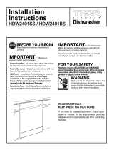
Figure Y
STEP 15 PRE-TEST CHECKLIST
Review this list after installing your dishwasher to
avoid charges for a service call that is not covered
by your warranty.
Check to be sure power is OFF.
Open door and remove all foam and paper
packaging.
Locate the Owner’s Manual in the literature
package.
Read the Owner’s Manual for operating
instructions.
Check door opening and closing. If door does not
open and close freely or tends to fall, check spring
adjustments. See Step 1.
Check to be sure that wiring is secure under the
dishwasher, not pinched or in contact with door
springs or other components. See Step 9.
Check door alignment with tub. If door hits tub,
level dishwasher. See Step 10.
Pull lower rack out, about half way. Check to be
sure it does not roll back or forward on the door.
If the rack moves, adjust leveling legs. See Step 10.
Check door alignment with cabinet. If door hits
cabinet, reposition or relevel dishwasher. See
Step 10.
Verify water supply and drain lines are not kinked
or in contact with other components. Contact with
motor or dishwasher frame could cause noise.
See Step 8.
Turn on the sink hot water faucet and verify water
temperature. Incoming water temperature must
be between 120°F and 150°F. A minimum of 120°F
temperature is required for best wash perfor-
mance. See “Prepare Hot Water Line,” page 5.
Add 2 quarts of water to the bottom of the dish-
washer to lubricate the pump seal.
Turn on water supply. Check for leaks. Tighten
connections if needed.
Remove protective film if present from the control
panel and door.
STEP 14 CONNECT POWER
SUPPLY
Skip this step if equipped with power cord.
Verify that power is turned off at the source.
• Remove junction box cover “A”.
• Locate the three dishwasher wires, (white, black and
green) with stripped ends. Insert dishwasher wires
through the small hole in the junction box “B”.
• Secure house wiring to the bottom of the junction
box with a strain relief “C”.
• Use wire nuts to connect incoming ground to green,
white to white and black to black “D”.
• Replace junction box cover “E”. Check to be sure
that wires are not pinched under the cover.
WARNING
If house wiring is not 2-wire with
ground, a ground must be provided
by the installer. When house wiring
is aluminum, be sure to use UL Listed
anti-oxidant compound and aluminum-
to-copper connectors
White
Ground
Black
Check That White, Black and
Green Dishwasher Wires Are Threaded
Thru Hole in Back
Remove
Junction Box
Cover
Insert Power
Cord Wires Thru
Strain Relief
and Tighten
Use UL Listed
Wire Nuts
A
C
B
D
E. Replace Junction Box Cover