Page is loading ...

Assembly Instructions
optoNCDT 1900LL
Pin Assignment
Signal Pin Cable color
PC1900-x
Description
+U
B
5 Red Supply voltage (11 ... 30 VDC)
GND 14 Blue
System ground supply,
switch signals (Laser on/off, Zero, Limits)
Analog output 1
Coaxial in-
ner conduc-
tor, white
Current 4 ... 20 mA (R
B
< (U
B
- 6 V) / 20 mA))
Voltage 0 ... 5 VDC
Voltage 0 ... 10 VDC (R
i
= 50 Ohm, I
max
= 5 mA)
AGND 2
Screening,
black
Reference potential for analog output
Laser on/off 3 Black
Switching input,
Laser operates when pin 3 is connected to GND
Multifunction input 13 Violet
Switching input,
TrigIn, Zero/Master, TeachIn, SlaveIn
Error/Limit 1 10 Brown Switching output 1
Limit 2 11 White
Switching output 2
Programmable switching behavior: (NPN, PNP, push-pull)
Sync + 17 Gray-pink
Symmetrical synchronous output (Master) or input (Slave).
RS422 level, 120 Ohm switchable for terminating, select-
able input or output depending on synchronization mode
Sync - 12 Red-blue
Tx + 8 Gray
RS422 - Output
(symmetric) terminate receiver with 120 Ohm
Tx - 15 Pink
Rx + 9 Green
RS422 - Input
(symmetric) internally terminated with 120 Ohm
Rx - 16 Yellow
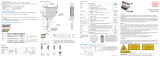
7
9
15
16
6
5
8
12
1 11 10
13 4 14
2
3
17
The PC1900 sensor cable is
qualified for drag chain use.
One end of the cable has
a molded cable connector,
the other end has braids
with ferrules.
Overall shield
Analog output
with shield
17-pin plug-in connector, M12, pin side of pigtail cable
connector
PC1900-x with open ends
Supply voltage, Nominal value: 24 V DC (11 ... 30 V, P < 3 W)
ILD1900
5
14
11 ...
30 VDC
Sensor
Pin
PC1900-x/Y
Color
Supply
Use supply voltage for measurement
instruments only. MICRO-EPSILON
recommends using an optional avail-
able power supply unit PS2020 for the
sensor.
5 red +U
B
14 blue Ground
X9771416.01-A012110HDR
MICRO-EPSILON MESSTECHNIK GmbH & Co. KG
Koenigbacher Str. 15 • 94496 Ortenburg • www.micro-epsilon.com
Your local contact: www.micro-epsilon.com/contact/worldwide/
Proper Environment
- Protection class: IP67 (applies only when the sensor cable is plugged in)
Optical inputs are excluded from protection class. Contamination leads to impairment or failure
of the function.
- Temperature range - Humidity: 5 - 95 %
(non-condensing)
Operation: 0 ... +50 °C (+32 ... +122 °F)
Storage: -20 ... +70 °C (-4 ... +158 °F) - Ambient pressure: Atmospheric pressure
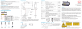
Sensor Mounting, Dimensions
The optoNCDT 1900LL sensor is an optical system for measurements with micrometer accuracy.
Pay attention to careful handling during mounting and operation.
Mount the sensor only to the existing holes on a flat surface. Clamps of any kind are not
permitted.
Mount the sensor by means of 2 screws type M4 or by means of through bores for M3 with
the screws from the accessories.
Measuring range, Start of Measuring Range
SMRMR
Current Voltage Digital value
1
3 mA 262077
4 mA (SMR) 98232
12 mA (MMR) 131000
20 mA (EMR) 163768
3 mA
5.2 V / 10.2 V
0 V
2.5 V / 5 V
5 V / 10 V
5.2 V / 10.2 V 262078
Sensor mounting with diffuse
reflection. The laser beam must
be directed perpendicularly onto
the surface of the target, other-
wise measurement uncertainties
cannot be excluded.
MR = Measuring range
SMR = Start of measuring range
MMR = Mid of measuring range
EMR = End of measuring range
1) For displacement values without
zero setting or mastering.
Mounting
Bolt connection Direct fastening
0.75 Nm
2.0 Nm
min 10
(.04)
M3 x 40; ISO 4762, A2-70 M4; ISO 4762, A2-70
screw depth min. 10 mm
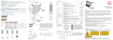
Drawings, Free Space
i
Mount the sensor only to the existing holes on a flat surface or screw it directly.
Do not exceed torques.
32
18
6
6
14
31 (1.22)
4x M4
45 (1.77)
4 (.16)
70 (2.76)
5 (.20)
2 (.08)
Y
2x ø6 H7
+0.012
0
2x 6 H7
+0.012
0
6 (.24)
60 (2.36)
SMR
MR
X
2 (.08)
Keep this area free from other
Limits for free space
light sources and/or their reflections.
Dimensions in mm (inches)
(1.26)
(.71)
(.55)
(.24)
(.24)
11
(.43)
Intended Use
The optoNCDT 1900LL system is designed for use in industrial and laboratory areas. It is used for
measuring displacement, distance and position as well as in in-process quality control and dimen-
sional testing. The sensor must only be operated within the limits specified in the technical data,
see operating instructions, Chap. 3.3. The sensor must be used in such a way that no persons are
endangered or machines and other material goods are damaged in the event of malfunction or total
failure of the sensor. Take additional precautions for safety and damage prevention for safety-related
applications.
Warnings
Avoid unnecessary laser radiation to be exposed to the human body. Switch off the sensor for clean-
ing and maintenance, for system maintenance and repair if the sensor is integrated into a system.
Caution - use of controls or adjustments or performance of procedures other than those specified
may cause harm.
Connect the power supply and the display-/output device according to the safety regulations for
electrical equipment. The supply voltage must not exceed the specified limits.
> Risk of injury. Damage to or destruction of the sensor.
Avoid constant exposure of sensor and controller. Avoid exposure of sensor and controller to ag-
gressive media (detergents, cooling emulsions).
> Damage to or destruction of the sensor.
Avoid shocks and impacts to the sensor. Protect the sensor cable against damage.
> Damage to or destruction of the sensor, failure of the measuring device.
Laser Safety
The ILD1900LL sensors operate with a semiconductor laser with a wavelength of 670 nm
(visible/red). The sensors fall within laser class 2. The laser is operated on a pulsed mode, the maxi-
mum optical power is ≤ 1 mW. Operation of the laser is indicated visually by LED state.
LASER RADIATION
DO NOT STARE INTO BEAM
CLASS 2 LASER PRODUCT
IEC 60825-1: 2014
P 1mW; =670nm
COMPLIES WITH 21 CFR 1040.10 AND 1040.11
EXCEPT FOR CONFORMANCE WITH IEC 60825-1
ED. 3., AS DESCRIBED IN
LASER NOTICE NO. 56, DATED MAY 8, 2019.
Laser radiation. Close your eyes or
immediately turn away if the laser
beam hits the eye. Irritation or injury
of the eyes possible.
Laser warning sign on the
sensor housing
Laser label on the sensor cable
optoNCDT
0.3 m
ILD1900LL with pigtail
optoNCDT
3 m
ILD1900LL with open ends
MR 10 25
SMR 20 25
X 33 33
Y 14 33
ø4.8 (.19)
ø6 H7
+
0.012
0
1.6
±0.05
60 (2.36)
±0.1
0.02
A
0.02
A
Dimensional drawing, drilling pattern, mounting plate
Alignment via centering elements (optional)

Initial Operation
Connect the sensor to a PC/notebook via a RS422 connector. Connect
the supply voltage.
Start the program sensorTOOL.
Click the Sensor button.
The program searches for connected ILD1900LL sensors on available inter-
faces.
The sensor-
TOOL program is
available at https://
www.micro-epsi-
lon.com/service/
download/soft-
ware.
You need a web
browser compati-
ble with HTML5 on
a PC/notebook.
Select the desired sensor. Click on the button Open Website.
Access via Web Interface
Interactive web pages for programming the sensor now appear in the web browser. The sensor is
active and supplies measurement values. The ongoing measurement can be operated by means
of function buttons in the area Measurement chart.
In the top navigation bar other functions (settings, measurement chart etc.) are available.
The appearance of the websites can change dependent on the functions. Each page contains
descriptions of parameters and so tips for filling the website.
Select a Measuring Rate
Go to the menu Settings > Data recording > Measuring rate.
Start with a medium measuring rate. Select a measuring rate from the list. Confirm with Apply.
Select an Interface
Go to the menu Settings > Outputs > Output interface.
Defines which interface is used for output of measured values. Parallel output o measured values
via multiple channels is not possible. RS422 and analog output cannot be operated simultane-
ously. While using the web interface, the output is switched off via RS422.
Place Target
Position the target (measuring object) as much as possible in the midrange.
100 %
50
0
SMR
Measuring object
Measuring range
SMR MMR EMR
Displacement
Signal
The State LED on the sensor indicates the position of the target to the sensor.
LED Color Labeling Meaning
State
off Laser off Laser beam is switched off
green In range Target within measuring range
yellow Midrange Target within the midrange
red Error
Target outside the measuring range,
too low reflection
Store the Settings
Go to the menu Settings > System settings > Load & Stores or click the Save
settings button.
Read the detailed operating instructions before using the sensor. The manual is available online
on www.micro-epsilon.de/download/manuals/man--optoNCDT-1900--en.pdf.
Switch on the Laser
PC1900-x
+U
3
1
blue
14
Type 1
ILD1900
H
Type 2 Type 3
black
GND
+U
10k
B
i
The laser remains off as
long as pin 3 is not elec-
trically connected with pin
14.
Analog Output
Current output 4 ... 20 mA or
Voltage output 0 ... 5 V or 0 ... 10 V
i
The current output may not be continu-
ously operated in short-circuit operation
without load resistor. This would lead to
thermal overload and thus to the auto-
matic overload cut-off of the output.
1
I
out
R
B
C
I
2
ILD1900
5
14
11...
30 VDC
Current output
R
B
< (U
B
-6 V) / 20 mA;
R
B
max. = 250 Ohm
at U
B
= 11 V
C
I
≤ 33 nF
Analog output
Pin 1,
coaxial inner con-
ductor, white
AGND Pin 2,
screening
1
U
out
R
L
R
i
C
U
2
ILD1900
5
14
11...
30 VDC
Voltage output
R
i
= 50 Ohm, I
max
= 5 mA,
Short circuit protection 7 mA
R
L
> 20 MOhm
C
U
≤ 100 nF
Multi-Function Input
The multi-function input enables triggering, zero setting/mastering and teaching. The function
depends on the programming of the input and on the timing of the input signal.
The inputs are not electrically isolated. The maximum switching frequency is 10 kHz.
PC1900-x
+U
13
1
blue
14
Type 1
ILD1900
H
+U
10k
B
Type 2 Type 3
violet
GND
24 V logic (HTL):
Low ≤ 3 V; High ≥ 8 V
(max 30 V)
5 V logic (TTL):
Low ≤ 0.8 V; High ≥ 2 V
internal pull-up resistor, an
open input is detected as High.
Connect the input to GND to trigger the function.
Quick Guide
Components
Mount the sensor and connect the components.
Source Cable/Supply Interface
USB
USB
Ethernet
PC
PS 2020
PC1900-x/IF2008 (IF2008-Y)
PC1900-x/C-Box/RJ45
Sensor supply by peripheral
device
PC1900-x/IF2008
and IF2008-Y
adapter cable
IF2004/USB
PC1900-x/OE
PC1900-x/OE
SPS
C-Box/2A
IF2001/USB
IF2030/PNET
IF2030/ENETIP
EtherNet/IP
PC1900-x/OE
IF2008/PCIE
RS422 Connection with USB Converter IF2001/USB
Cross the lines for connections between sensor and PC.
i
Disconnect or connect the D-sub connection between RS422 and USB converter when the
sensor is disconnected from power supply only.
Sensor End device (converter)
Type IF2001/USB
from MICRO-EPSILON
17-pin cable
connector
Sensor
cable
Tx + (Pin 8) Gray Rx + (Pin 3)
Tx -(Pin 15) Pink Rx -(Pin 4)
Rx + (Pin 9) Green Tx + (Pin 1)
Rx -(Pin 16) Yellow Tx -(Pin 2)
GND (Pin 14) Black GND (Pin 9)
Symmetric differential signals acc. to EIA-422, not electrically isolated from supply voltage. Use a
shielded cable with twisted cores e.g. PC1900-x.
/