68-2319-50 Rev. A
01 14
© 2014 Extron Electronics — All rights reserved. All trademarks mentioned are the property of their respective owners. www.extron.com
Step 3 — Make rear panel connections
a. Connect a twisted pair cable between the XTP connector (see
a
of gure 1) of the XTP T EU 202 or XTP T MK 202 to an XTP receiver.
ATTENTION: Do not connect this connector to a computer data or telecommunications network.
The XTP transmitters are compatible with shielded twisted pair (F/UTP, SF/UTP, and S/FTP) and unshielded
twisted pair (U/UTP) cables. Extron recommends using the following practices to achieve full transmission
distances up to 330 feet (100 meters) and reduce transmission errors.
• Use Extron XTP DTP 24 SF/UTP cable for the best performance. If not using XTP DTP 24 cable, at a
minimum, Extron recommends 24 AWG, solid conductor, shielded twisted pair cable with a minimum
bandwidth of 400 MHz.
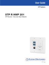
• Terminate cables with shielded connectors to the TIA/EIA-T568B standard.
• Limit the use of more than two pass-through points, which may include patch points, punch down
connectors, couplers, and power injectors. If these pass-through points are required, use shielded
couplers and punch down connectors.
NOTE: When using shielded twisted pair cable in bundles or conduits, consider the following:
• Do not exceed 40% ll capacity in conduits.
• Do not comb the cable for the rst 20 m, where cables are straightened, aligned, and secured in tight bundles.
• Loosely place cables and limit the use of tie wraps or hook and loop fasteners.
• Separate twisted pair cables from AC power cables.
Signal LED — Lights when the device is transmitting a video signal or a test pattern.
Link LED — Lights when a valid link between an XTP input and output is established.
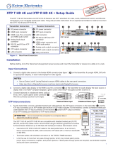
b. To pass bidirectional serial, infrared, or other control signals, connect a control device or a device to be
controlled to the RS-232 and IR Over XTP connector (see
b
of gure 1). Wire the connector as shown to the
right.
NOTE: RS-232 and IR data can be transmitted simultaneously.
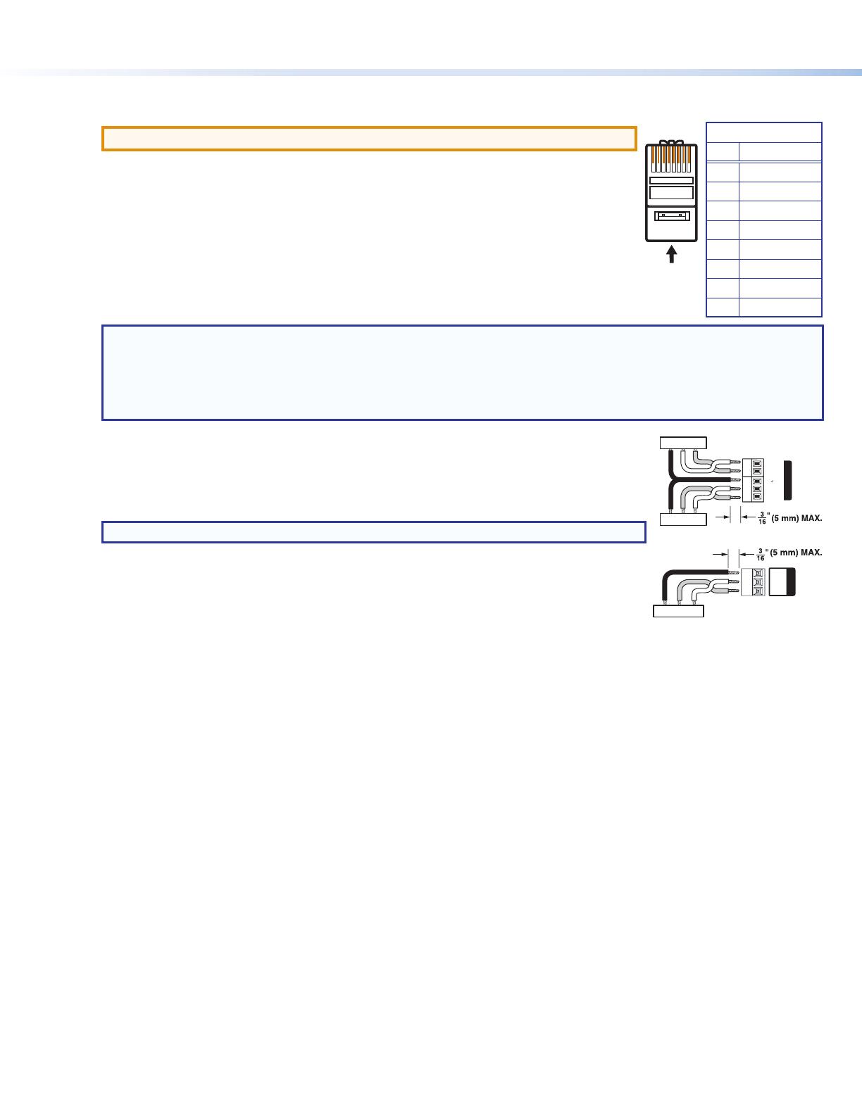
c. For serial RS-232 control, connect a host device or control system to the 3.5 mm, 3-pole captive screw
connector (see
c
of gure 1). Wire the connector as shown to the right.
d. Power the XTP transmitters in one of the following methods:
• Connect the provided external power supply to the 2-pole captive screw connector for local 12 V
power (see f of gure 1).
• Connect an XTP Power Injector to the XTP connection between an XTP transmitter and a locally powered XTP receiver or XTP matrix
switcher.
• Connect the XTP transmitter to an XTP matrix switcher and enable the remote power feature on the XTP matrix switcher.
Step 4 — Mount the device
Using the provided screws, attach the device to the four mounting anges on the mounting plate.
Step 5 — Connect inputs
a. Connect a digital video source to the female HDMI connector (see
g
of gure 1). It accepts HDMI, DVI (with an appropriate adapter), or dual
mode DisplayPort video signals.
b. Connect an unbalanced analog audio input source to the 3.5 mm TRS jack (see
h
of gure 1).
c. Connect an analog RGB video source to the female 15-pin HD VGA connector (see
i
of gure 1).
d. Connect a host device to the mini-USB B connector for conguration, control, and rmware upgrades (see d of gure 1).
Operation
Configuration and Control
After the XTP transmitter and all connected devices are connected and powered on, the system is fully operational. If any issues arise, verify
that the cables are routed and connected properly. Use the Extron XTP System Configuration software or SIS commands to configure the XTP
transmitter (for more details, see the XTP T EU 202 and XTP T MK 202 User Guide on the Extron website, www.extron.com).
Indicators
Power LED — Lights when power is applied to the device.
HDCP LED — Lights when an input signal is HDCP compliant.
HDMI LED — Lights when an HDMI input signal is detected.
VGA LED — Lights when a VGA input signal is detected.
TIA/EIA-T568B
Pin Wire Color
1 White-orange
2 Orange
3 White-green
4 Blue
5 White-blue
6 Green
7 White-brown
8 Brown
12345678
RJ-45
Connector
Insert Twisted
Pair Wires
Pins:
Pin
1
2
3
4
5
6
7
8
Wire color
White-green
Green
White-orange
Blue
White-blue
Orange
White-brown
Brown
Wire color
T568A T568B
White-orange
Orange
White-green
Blue
White-blue
Green
White-brown
Brown
Tx/Rx
Pins
Tx
Rx
Rx Tx
IR Device
RS-232 Device
G
G
Tx Rx
G
OVER XTP
RS-232 IR
Tx
Rx
Rx TxGnd
Tx Rx
G
REMOTE
RS-232