Page is loading ...


Refreshment Center Operator’s Guide Table of Contents
December 2004 i 4800006
TABLE OF CONTENTS
Introduction................................................................................................................. 1
Power Requirements............................................................................................................................. 3
Unpack the Machine ............................................................................................................................. 3
Controls and Indicators......................................................................................................................... 4
Turn the Merchandiser ON and OFF.................................................................................................... 6
Initial Set-Up................................................................................................................ 7
Moving the Merchandiser Through a Narrow Doorway ...................................................................... 7
Open the Rear Outlet Diffuser.............................................................................................................. 9
Position the Merchandiser .................................................................................................................... 9
Configure Machine for Dual Zone...................................................................................................... 10
Tray Set-Up................................................................................................................ 17
Place a Tray in the Loading Position.................................................................................................. 17
Set up Trays to Vend Products ........................................................................................................... 18
Set Up A Tray To Vend Wide Products ............................................................................................. 18
Remove a Snack or Candy Tray......................................................................................................... 19
Remove a Bottle Tray......................................................................................................................... 21
Remove and Install Column Dividers................................................................................................. 22
Operate a Tray Outside of the Machine.............................................................................................. 22
Replace a Motor with a Spiral Bearing............................................................................................... 23
Connect and Disconnect a Motor Harness.......................................................................................... 24
Remove and Install Spirals ................................................................................................................. 25
Remove a Spiral Coupler.................................................................................................................... 26
Remove and Install a Spiral Motor..................................................................................................... 27
Install a Gear....................................................................................................................................... 28
Install a Spiral Coupler ....................................................................................................................... 29
Move a Tray Up or Down................................................................................................................... 30
Install a Tray in the Merchandiser ...................................................................................................... 31
Install and Remove a Product Spacer ................................................................................................. 32
Load the Merchandiser............................................................................................. 33
General Tray Loading:........................................................................................................................ 33
Special Considerations:....................................................................................................................... 33
Spiral Wall Retainer Usage................................................................................................................. 34
Product Pusher Usage......................................................................................................................... 35
Configure the Merchandiser to vend “Lunch Buckets”...................................................................... 35
Configure the Merchandiser for Vending "Top Shelf"....................................................................... 36
Return the Trays to the Vending Position........................................................................................... 37
Install and Set Price Labels................................................................................................................. 38
SureVend™................................................................................................................ 41
Health Control........................................................................................................... 42
Final Installation ....................................................................................................... 44
Level the Merchandiser ...................................................................................................................... 44
Install the Base Plate........................................................................................................................... 45
Install the Lock Cylinder .................................................................................................................... 46

Table of Contents Refreshment Center Operator’s
4800006 ii December 2004
Install the Optional Cash Box Lock.................................................................................................... 46
Set Up the Coin Mechanism ............................................................................................................... 47
Load the Coin Mechanism.................................................................................................................. 47
Operational Readiness Check............................................................................................................. 48
Spiral Indexing Procedure (One Spiral, One Motor).......................................................................... 48
Spiral Indexing Procedure (Two Spirals, One Or Two Motors)......................................................... 49
Test the Bill Validator......................................................................................................................... 49
Programming Intro................................................................................................... 50
The Displays ....................................................................................................................................... 50
The Function Keys.............................................................................................................................. 51
Other Keys .......................................................................................................................................... 51
Control Panel Switches Explained...................................................................................................... 52
Programming Flow Charts.................................................................................................................. 53
Programming Procedures......................................................................................... 55
Enter a New Supervisor Code ............................................................................................................ 55
Enter a Freevend Code ....................................................................................................................... 55
Lock Or Unlock Mode Or Payout Keys ............................................................................................ 56
Turn Talker Mode On or Off ............................................................................................................. 56
Set DEX Options ...............................................................................................................................57
Select Display Language ...................................................................................................................58
Select Coin Mechanism .....................................................................................................................58
Select Card Reader and Options ........................................................................................................ 60
Set Temperature ................................................................................................................................. 64
Enable or Disable Trays .....................................................................................................................65
Set SureVendUp the SureVend Anti-Jackpot Feature...................................................................... 66
Set first in - first out(fifo) mode .........................................................................................................68
Show the Temperature in Standby Mode .......................................................................................... 69
View Surevend Software version ....................................................................................................... 70
View Software Version ...................................................................................................................... 70
Set the Date ........................................................................................................................................71
Set Daylight Savings Option .............................................................................................................. 71
Set Time-Of-Day Free Vending ......................................................................................................... 72
Set Time-Of-Day Discount Vending ................................................................................................. 72
Time Interval Editing .........................................................................................................................72
Select a Standby Message .................................................................................................................. 74
Select a Freevend Message ................................................................................................................ 75
Set Prices ............................................................................................................................................78
View Sales Data Three Different Ways ............................................................................................. 79
View Card Reader Paid Sales ............................................................................................................ 79
View Total Paid Vends ...................................................................................................................... 80
Clear All Resettable Data .................................................................................................................. 80
View Amount In Coin Box ................................................................................................................ 81
View Amount In Validator ................................................................................................................81
View Discount Sales By Time Interval ............................................................................................. 82
View Free Vends ...............................................................................................................................82
View Time Data................................................................................................................................. 83
View Total Unpaid Vends .................................................................................................................85

Refreshment Center Operator’s Guide Table of Contents
December 2004 iii 4800006
View Number Of Test Vends ............................................................................................................ 85
View Machine ID Number ................................................................................................................ 85
Test the Motors .................................................................................................................................. 87
Download Data To A PDCD ............................................................................................................. 90
Set Freevend Options ......................................................................................................................... 90

Table of Contents Refreshment Center Operator’s
4800006 iv December 2004

Refreshment Center Operators’ Guide Introduction
December 2004 1 4800006
Section 1: Introduction
Exterior View

Introduction Refreshment Center Operators’ Guide
4800006 2 December 2004
Interior View

Refreshment Center Operators’ Guide Introduction
December 2004 3 4800006
Power Requirements
The merchandiser is supplied with a service cord for the country of use and is terminated in
a grounding type plug. The wall receptacle used for this merchandiser must be properly
polarized, grounded, and of the correct voltage. Operating the merchandiser from a source
of low voltage will VOID YOUR WARRANTY. Each merchandiser should have its own
electrical circuit and that circuit should be protected with a circuit breaker or fuse conforming
to local regulations.
1. Voltage Check - Place the leads of a voltmeter across the LINE (LIVE) and NEUTRAL
terminals of the wall receptacle. The voltmeter should indicate 110-130 volts AC for 120
volt, 60 Hz locations, or 220- 240 volts AC for 230 volt, 50 Hz locations.
2. Polarity Check - Place the leads of a voltmeter across the LINE (LIVE) and GROUND
terminals of the wall receptacle. The voltmeter should indicate 110-130 volts AC for 120
volt, 60 Hz locations, or 220- 240 volts AC for 230 volt, 50 Hz locations.
3. Noise Potential Check - Place the test leads of a voltmeter across the NEUTRAL and
GROUND terminals of the wall receptacle. The meter should indicate 0 volts AC. A
measurement greater than 1.5 - 2.0 volts AC could result in problems for the
merchandiser's electronic circuitry caused by electrical noise.
Any deviation from these requirements could result in unreliable performance from your
merchandiser.
Unpack the Machine
Remove all packing materials from the interior of the machine. Keep all documents;
warranty cards, etc. Set aside the base plate kit (if present).

Introduction Refreshment Center Operators’ Guide
4800006 4 December 2004
Controls and Indicators
DOOR SWITCH. When the cabinet door is open, this switch turns off the compressor and
evaporator fan.
INTERLOCK SWITCH. (230 volt models only) Turns off the glass heater and display lights
when the cabinet door is open. Pull the switch out to restore high voltage for maintenance.
LOW VOLTAGE SWITCH. Tells the controller software the main door is open or closed.
MESSAGE DISPLAY. This is how the merchandiser communicates with the outside world.
Customers can see messages about how much money they have put into the merchandiser.
The message display also tells customers when a selection is sold out and when vending is
free, inhibited, or discounted. The message display shows you what you are doing when
you program the merchandiser, and can show you what is wrong if there is a failure.
FREE VEND KEYSWITCH (OPTIONAL). This allows someone (other than maintenance
personnel) to set the merchandiser to free vend without opening the door.
SELECTION KEYPAD. The customer uses this keypad to make selections. Maintenance
people may use this keypad during programming.
COIN RETURN BUTTON. Returns any coins paid into the merchandiser prior to a vend.
BILL ACCEPTOR (OPTIONAL). Accepts bills of various denominations, depending upon
the type of bill validator, and how the machine is configured.
SERVICE KEYPAD. The service keypad is located at the top of the monetary panel. It
gives service personnel the means to program, retrieve data from, and view diagnostic
information about, the merchandiser.

Refreshment Center Operators’ Guide Introduction
December 2004 5 4800006
MAIN CONTROLLER PCB DISPLAY. This display consists of two light emitting diodes
(LED) mounted on the controller PCB.
"CAUTION - Risk of explosion if battery is replaced with an incorrect type. Dispose of used batteries according
to the manufacturer's instructions."
POWER ON
(LED 1)
When lit, this red LED indicates electrical power is applied to the
controller PCB.
HEARTBEAT
(LED 2)
When flashing, this red LED indicates that the controller PCB is
active, and the software is operating.
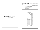
Back Side of U.S./Canada Power Panel.
The
circuit board mounted on the rear of the power
panel is a DC power supply for the coin
mechanism. A fuse protects the board circuitry in
the event of a coin mechanism solenoid failure. If
the coin mechanism is not working, check this
fuse. If the fuse is blown, a bad coin mechanism
solenoid could be at fault.
NORMAL CONDITIONS:
When the merchandiser is operating normally, you should see a steady red
POWER ON indicator and a flashing red HEARTBEAT indicator. Contact a
service representative if any other condition exists.
DC POWER
SUPPLY PCB
F
OR 110V COIN MECH
˜
AGC
1
FUS
E
1 AM
P
TOP
BACK SIDE
OF
U.S. / CANADA POWER CONTROL PANEL

Introduction Refreshment Center Operators’ Guide
4800006 6 December 2004
Turn the Merchandiser ON and OFF
• Power to the merchandiser is controlled by the main power switch, located on the
power panel.
• The power panel is on the right side of the merchandiser, behind the monetary
panel.
WARNING
Lethal voltages are present. Unplug the merchandiser before you perform any of the
following tasks:
• Change a fuse
• Change the fluorescent lamp
• Change the lamp starter
• Connect or disconnect a harness (except a motor harness when the tray has been
removed)
Failure to do so may result in personal injury.
US / CANADA POWER PANEL INTERNATIONAL POWER PANEL
LABEL
MAIN
POWER
SWITCH
LOW VOLTAGE
CIRCUIT BREAKER
OFF
ON
626p0040
LABEL
MAIN
POWER
SWITCH
ELECTRONICS
BREAKER
O
I
626P0005

Refreshment Center Operators’ Guide Initial Set-Up
December 2004 7 4800006
Section 2: Initial Set-Up
Moving the Merchandiser Through a Narrow Doorway
NOTE
If necessary, this merchandiser can be moved through an opening as narrow as 30
inches by removing panels at the top and bottom of the cabinet.
Remove the Bottom and Top Panels:
1. Remove the screws that secure the top and bottom knock-out panels to the cabinet.
2. Lift panels upward to remove them from the cabinet.

Initial Set-Up Refreshment Center Operators’ Guide
4800006 8 December 2004
Move the Merchandiser through the Opening:
1. Open the cabinet door and place it square with the left side of the cabinet.
2. Carefully walk the merchandiser through the opening.
Reassemble the Merchandiser:
1. Replace the upper and lower panels.

Refreshment Center Operators’ Guide Initial Set-Up
December 2004 9 4800006
Open the Rear Outlet Diffuser
The rear outlet diffuser vents warm air up and out of the back of the merchandiser, away
from the air inlet (on the bottom of the cabinet). It is shipped in the closed position and must
be opened before the merchandiser is put into service.
1. Remove the two screws holding
the upper corners of the diffuser
against the back of the cabinet.
Notice the two unused screw holes
at the corners.
NOTE:
Wear protective gloves when
bending diffuser to prevent
injury.
2. Pull the top of the diffuser away
from the cabinet, then bend the
diffuser so that the unused screw
holes align with the holes in the
cabinet.
3. Use the two screws removed in
step one to affix the diffuser to the
cabinet in its new “open” position.
CAUTION
The merchandiser will not function properly if the Rear Outlet Diffuser is not open!
Position the Merchandiser
Move the merchandiser to its approximate position. There are certain procedures you
need to perform before it is in its permanent location. Plug in your merchandiser and turn
the power switch to ON.
• You can position this merchandiser anywhere in a bank of machines. It can even
be placed on an end flush against a side wall.
• The merchandiser should be placed at least four inches away from the back wall
(six inches if rear diffuser is not installed). This will provide adequate air circulation
for the refrigeration unit. This will provide adequate air circulation for the
refrigeration unit.
• The merchandiser will operate more efficiently when placed in a shaded location.
• There should be enough room in front of the merchandiser for the door to move
freely.
CAUTION
This machine is only rated for installation at an indoor location.

Initial Set-Up Refreshment Center Operators’ Guide
4800006 10 December 2004
Configure Machine for Dual Zone
To configure your machine for dual zone you must first know what duct system your machine
has. There are two different duct systems. There is a version 1 duct system which uses a tall
air supply panel (as shown in figure 1 and 2). This air supply panel will extend all the way to
the top of the machine. Version 2 duct system which uses a short air supply panel (as shown
in figure 3) will only extend about half way up the machine.
Both duct systems have two different configurations for the dual zone option. There is a two
tray configuration and a three tray configuration.
If you have a version 1 duct system and you are configuring your machine for a two tray
configuration: (See Figure , “Figure 1,” on page 11)
If you have a version 1 duct system and you are configuring your machine for a three tray
configuration: (See Figure , “Figure 2,” on page 13)
If you have a version 2 duct system and you are configuring your machine for a two tray or a
three tray configuration: (See Figure , “Figure 3,” on page 15)
Note:
If you are not using dual zone in the merchandiser then you must remove the
barrier, foam boards, air deflector, and the air plate.
The temperature sensor will be mounted on the top left hand
side of the cabinet.

Refreshment Center Operators’ Guide Initial Set-Up
December 2004 11 4800006
Set machine for two tray configuration version 1:
FIGURE 1

Initial Set-Up Refreshment Center Operators’ Guide
4800006 12 December 2004
Version 1 duct system two tray configuration
(See Figure , “Figure 1,” on page 11)
1. You must first remove all trays from your merchandiser.
2. Remove the right tray rail guide for tray A shelf.
3. Remove the tray rail board and the tray shield from the second tray guide rail in the
machine.
4. Re-attached the tray shield to the second tray rail.
5. Mount the tray rail board and the to the right side of the barriers mounting rail standoffs.
6. Remove the temperature sensor bracket mounted to the left hand side of the cabinet.
Do not unplug the sensor, let it hang down the left hand side of the cabinets wall.
7. Position the barrier inside the cabinet just below the second trays rails. Make sure that
the third tray rail connector plug is left underneath the barrier. You will need to remove
the left hand side tray rails underneath the barrier in order to position the barrier.
8. Mount the barriers mounting rails to the sides of the machine using one screw for each
rail.
9. Move the barrier to the back right corner of the cabinet leaving a gap on the left hand
side of the barrier.
10. Place the 1/2” by 1/2” piece of foam tape on the left side of the cabinet in between the
barrier and the cabinet where you have left the gap.
11. Place the large foam board at the upper right side of the air supply panel.
12. Place the small foam board next to the large foam. Make sure that the small boad is at
the bottom of the large board.
13. Bend the flanges on the air supply panel to hold the foam boards in place.
14. Mount the air plate directly under the barrier on the right side of the air supply panel.
15. Mount the air deflector in front of the air plate under the barrier. (The opening should be
facing you.)
16. Re-mount all tray rails and re-connect all rail connections.
17. Replace all snack and candy trays. You may have to adjust the tray rails underneath the
barrier to provide adequate spacing for your trays.
18. Re-mout the temperature probe underneath the barrier in the holes provided on the left
inside wall of the cabinet.

Refreshment Center Operators’ Guide Initial Set-Up
December 2004 13 4800006
Set the machine for three tray configuration version 1:
Note:
If you are using a three tray configuration you will not use the air deflector and
the air plate.
FIGURE 2

Initial Set-Up Refreshment Center Operators’ Guide
4800006 14 December 2004
Version 1 Duct system three tray configuration
(See Figure , “Figure 2,” on page 13)
1. You must first remove all trays from your merchandiser.
2. Remove the right two tray rail guides for tray A and B shelf.
3. Remove the tray rail board and the tray shield from the third tray guide rail in the
machine.
4. Re-attached the tray shield to the third tray rail.
5. Mount the tray rail board and to the right side of the barriers mounting rail standoffs.
6. Remove the temperature sensor bracket mounted to the left hand side of the cabinet.
Do not unplug the sensor, let it hang down the left hand side of the cabinets wall.
7. Position the barrier inside the cabinet just below the third trays rails. Make sure that the
fourth tray rail connector plug is left underneath the barrier. You will need to remove the
left hand side tray rails underneath the barrier in order to position the barrier.
8. Mount the barriers mounting rails to the sides of the machine using one screw for each
rail.
9. Move the barrier to the back right corner of the cabinet leaving a gap on the left hand
side of the barrier.
10. Place the 1/2” by 1/2” piece of foam tape on the left side of the cabinet in between the
barrier and the cabinet where you have left the gap.
11. Place the large foam board at the upper right side of the air supply panel.
12. Place the small foam board directly underneath the large foam.
13. Bend the flanges on the air supply panel to hold the foam boards in place.
14. Re-mount all tray rails and re-connect all rail connections.
15. Replace all snack and candy trays. You may have to adjust the tray rails underneath the
barrier to provide adequate spacing for your trays.
16. Re-mout the temperature probe underneath the barrier in the holes provided on the left
inside wall of the cabinet.

Refreshment Center Operators’ Guide Initial Set-Up
December 2004 15 4800006
Set the machine for a two or three tray configuration version 2:
FIGURE 3
/