Page is loading ...

QUICK REFERENCE GUIDE
IC260L/D DUO
IC261L/D DUO
(Firmware rel. 1.9)

1592015870 Quick reference guide IC260_261L_D DUO FW 1.9 05-04-2016 IC260/261L/D 2/64
Index
1. General Advice _______________________ 2
2. General Features _____________________ 3
3. IC200 L/D Table of the Features __________ 4
4. User Interface _______________________ 6
5. Remote Keyboard ____________________ 8
6. First Installing ________________________ 8
7. Display Layout _______________________ 9
8. Programming with the “Hot key 64” _______ 9
9. Parameter Programming using the
keyboard __________________________ 10
10. Function Menu “ M” Key _______________ 12
11. Set point modification _________________ 14
12) Installing And Mounting________________ 14
13. Electrical Connections ________________ 15
14. Table Of The Output Status In Alarm
Condition___________________________ 16
15. Wiring Connections __________________ 19
16. Probe and relay configuration __________ 21
17. Table Of The Parameters ______________ 26
18. Technical Data ______________________ 63
1. General Advice
1.1 Please Read Before Using This Manual
This manual is part of the product and should be kept near
the instrument for easy and quick reference.
The instrument shall not be used for purposes different from
those described hereunder. It cannot be used as a safety
device.
Check the application limits before proceeding.
Dixell Srl reserves the right to change the composition of its
products, even without notice, ensuring the same and
unchanged functionality.
1.2 Safety Precautions
Check the supply voltage is correct before connecting the
instrument.
Do not expose to water or moisture: use the controller only
within the operating limits avoiding sudden temperature
changes with high atmospheric humidity to prevent formation
of condensation
· Warning: disconnect all electrical connections before any kind
of maintenance.
The instrument must not be opened.
In case of failure or faulty operation send the instrument back
to the distributor or to “ Dixell s.r.l.” (see address) with a
detailed description of the fau lt.
Consider the maximum current which can be applied to each
relay (seeTechnical Data).
Ensure that the wires for probes, loads and the power supply
are separated and far enough from each other, without
crossing or intertwining.
Fit the probe where it is not accessible by the end user.
In case of applications in industrial environments, the use of
mains filters (our mod. FT1) in parallel with inductive loads
could be useful.
Full Manual
Dixell S.r.L. reserve to itself the right to modify this
instruction manual without any warning.
Last available can be downloaded from he internet
site. dixell@emerson.com

1592015870 Quick reference guide IC260_261L_D DUO FW 1.9 05-04-2016 IC260/261L/D 3/64
2. General Features
iCHILL IC200L/D is an electronic controller for chiller unit
applications having one or two circuits:
Air/air
Air/water
Water/water
Motocondensing
Additional features :
Heat pump with gas reversibility
2.1 Main Function
Chiller management:
One circuit up to 4 compressors
Two circuits with different compressor number per circuit
Double circuit up to 6 compressors
Screw compressors
Compressor start up:
Direct
Part winding
Star - delta
Compressor Soft start:
With step valve
Automatic start-unloading (without load).
External by-pass gas valve.
Capacity step control:
Continuous control
Step control
Modulation control (screw compressors)
Thermoregulation of the compressors
Time running hours
Number of start-up per hour
Cooling liquid injection
With dedicated PTC probe
High temperature alarm of the compressor discharge side
With dedicated PTC probe
Complete management of two pump groups of the water side
2 pumps evaporator side
2 pumps condenser side
Display layout customizable
Temperature
Pressure
Time / RTC in real time
Other display readings
Safety digital inputs
Compressors running hours
Number of compressor start-up
Pump running hours
Delay counting to the next defrost
Proportional output percentage status
Compressors discharge temperature
Alarm reset with custom password
Alarm list
Compressor thermal protection alarm
Single circuit stand-by
Circuit maintenance
To work with only one circuit
Single compressor stand-by
Compressor maintenance
Compressor malfunction
Pump down management
With dedicated pressure switch
Low pressure switch
Low pressure transducer
Unloading circuit
High temperature of the evaporator inlet water
High temperature of the condenser inlet water (unit with
recovery)
High condensing pressure
Low evaporating pressure
Maintenance messages
Compressors
Evaporator pumps
Condenser pumps
Auxiliary relays
Two configurable relay outputs not depending from the
control algorithm can be managed through NTC, PTC or
pressure probes.
Weekly Energy saving
Three different time bands per day (only with RTC onboard)
From digital input
Weekly ON/OFF:
Three different time bands per day (only with RTC onboard)
Dynamic setpoint:
Determined by analogue NTC input or 4÷20mA current
input.
Change over :
Automatic chiller or heat pump functioning depending from
NTC analogue input.
Remote OFF:
From configurable digital input.
Remote change over:
From configurable digital input.
Hot start :
Air / air unit
Defrost management:
Combined control with temperature and pressure

1592015870 Quick reference guide IC260_261L_D DUO FW 1.9 05-04-2016 IC260/261L/D 4/64
Forced defrost with low temperature of external air
From configurable digital input
Manual from keyboard
Boiler:
For electrical integration heating or anti-freeze heaters
Two proportional outputs for condensing fan speed control
(inverter or phase cut) with configurable signal:
PWM
0÷10Volt
4÷20mA
Four proportional control outputs 0÷10V or ON/OFF
To control the dumper in free cooling or recovery
To control an external relay
Complete alarm management
Internal Data logger up to 100 events
Supervisor / tele assistance/ monitoring
TTL output for XJ485 interface (Mod #Bus protocol) for
XWEB300 / XWEB3000 Dixell monitoring syste m for local and
remote control
Up to 2 remote terminals with display read-out customizable
With NTC ambient temperature probe
3. IC200 L/D Table of the Features
FEATURES
IC260L/D
IC261L/D
OUTPUT RELAYS
10
14
DIGITAL INPUTS
18 (free voltage)
configurable
configurable
PROBE INPUTS
6 (NTC - PTC)
configurable
configurable
4 (NTC - PTC - 4÷20mA - 0 ÷ 5Volt)
configurable
configurable
PROPORTIONAL OUTPUTS
2 PWM outputs (condensing fan management)
2 0÷10V or 4÷20mA (condensing fan management)
configurable
configurable
4 0÷10V outputs
configurable
configurable
OTHER OUTPUTS
TTL / RS – 485 with Mod-Bus-Rtu protocol
Output for remote keyboard VI620
POWER SUPPLY
12 Vac/dc (+15%;-10%)
24 Vac/dc (± 10%)
opt
opt
TOP DISPLAY

1592015870 Quick reference guide IC260_261L_D DUO FW 1.9 05-04-2016 IC260/261L/D 5/64
± 3 led with decimal point
BOTTOM DISPLAY
± 4 led with decimal point
OTHERS
Internal clock
opt
opt
Buzzer
opt
opt
configurable = configurable through parameter
opt = optional
= default

1592015870 Quick reference guide IC260_261L_D DUO FW 1.9 05-04-2016 IC260/261L/D 6/64
4. User Interface
4.1 Meaning of the leds: models IC260L / IC261L
4.2 Meaning of the leds: remote keyboard

1592015870 Quick reference guide IC260_261L_D DUO FW 1.9 05-04-2016 IC260/261L/D 7/64
4.3 Meaning of the icons
ICON
MEANING / FUNCTIONNING
Celsius degrees:
Fahrenheit degrees:
Bar:
PSI
Psi:
ON = compressor 1 active
ON = compressor 2 active
ON = compressor 3 active
ON = compressor 4 active
ON = compressor 5 active
ON = compressor 6 active
General alarm:
Anti freeze heaters/ integration
heating / boiler:
Flow alarm
Real time clock:
Water pump: On
Condenser fan: ON
4.4 Meaning of the leds: lower display
Led 1 – 2 (With RTC)
If the bottom display shows the RTC the 1 and 2 leds
are blinking.
Led 1 – 2 In function Menu
During the time counting to the next defrost for one or
both circuits the led 1 and 2 are blinking.
LED Parameter programming
In Pr2 level: led 3 indicates the visibility
while the 1 and 2 show if the parameter can
be modified or not.
In Pr3 level: led 3 and 4 indicate the visibility while the
1 and 2 show if the parameter can be modified or not.
4.5 Key Function
KEY
ACTION
FUNCTION
Push and release
Show chiller set point SetC and
heat pump SetH
Push two times
In chiller or heat pump if the
Energy saving or the Dynamic
setpoint are enabled it shows the
real setpoint Setr, the led is
blinking.
Push for 3
seconds the
release
Change between chiller / heat
pump
During the
programming:
push one time
Select a parameter or confirm a
value
Push one time
with probe label
showed on the
bottom display
Change between the read-out of
the circuit 1 and the circuit 2 and
viceversa
Push one time
Select the readings of the first
circuit
Pushing one time
during the
programming
To change the parameter code or
value
Push for 1
second during
the programming
1 time shows the Pr2 programming
level
2 time shows the Pr3 programming
level
Push one time
Select the readings of the second
circuit
Pushing one time
during the
programming
To change the parameter code or
value
Push one time
Turn the chiller on, if the unit is on
led is on
The led is blinking if there is a
power on delay or during the
pump down

1592015870 Quick reference guide IC260_261L_D DUO FW 1.9 05-04-2016 IC260/261L/D 8/64
Push one time
Turn the heat pump on, if the unit
is on led is on
The led is blinking if there is a
power on delay or during the
pump down
Push one time
enter the function Menu
Push for 3
seconds
To set RTC parameters (if the RTC
is inside)
Pushing one time
during the
programming
To exit from a group of parameter
4.6 Key Combinantion
4.7 Led and Icons
ICON
LED
FUNCTION
ON
Auxiliary relay #1 active
OFF
Auxiliary relay #1 not active
ON
Auxiliary relay #2 active
OFF
Auxiliary relay #2 not active
BLINKING
Defrost delay counting active
ON
Defrost
OFF
Defrost end
5. Remote Keyboard
The iCHILL can be connected with 2 remote terminals.
Each remote keyboard can have the probe on board
that is used to show the loacl temperature and also to
control the temperature regulation. For the
connections use shielded cable for a maximum lenght
of 150mt. In case of no communication between the
instrument and the remotes the upper display shows
“ noL” (no link). Use the connection cable CAB/CJ30
(2x0.2 mm
2
) to interface the ichill connector to the
shielded wire.
6. First Installing
6.1 On Board Clock (Optional)
Giving power supply the bottom display shows “ rtC”
alternated with a temperature or pressure value: It is
necessary to set the RTC.
If the probes are not connected the display shows the
corresponding probe alarm messages. In this situation
the RTC setup and the programming are available.
ATTENTION
The RTC function is an optional and it is not
possible to update the instrument but it is
necessary to order the instrument already
complete of this features.
With power failure the RTC back-up battery maximum
duration is 1 week. After this period it is necessary to
setup the clock again.
6.2 RTC Setup
1. Push M key for 3 seconds until the bottom
display shows “Hour” and the top display shows
its value.
2. Push SET one time: the value is blinking.
3. Use the Up and Down keys to adjust it. Push SET
one time to confirm; automatically the display
shows next parameter.
KEY
ACTION
FUNCTION
Push for 3 seconds
together
Enter the
programming
In Pr3 level: push SET
and the push DOWN
key
Select the
parameter level
visibility Pr1 / Pr2 /
Pr3
Push one time
together
Exit the
programming
Push 5 seconds (heat
pump with ok
condition)
Manual defrost
In Pr3 programming
level Push SET and
then the MENU key
In Pr3 defines if the
parameter can be
changed or not in
the other levels.

1592015870 Quick reference guide IC260_261L_D DUO FW 1.9 05-04-2016 IC260/261L/D 9/64
4. Repeat the operations 2. 3. and 4. for all the
RTC parameters:
- Min: minutes (0÷60)
- UdAy: day of the week (Sun = Sunday, Mon
=Monday, tuE =Tuesday, UEd = Wednesday,
tHu = Thursday, Fri =Friday, SAt =Saturday)
- dAy: day of the month (0÷31)
- MntH: month (1÷12)
- yEAr: year (00÷99)
-
7. Display Layout
As default, In normal condition, the display shows the
circuit 1 information.
The displayed circuit is indicated from the
corresponding led Cir1 on (UP key), or Cir2 (circuit 2,
DOWN key).
7.1 How to read temperature and
pressure
When the led Cir1 is on, push UP or Down keys to
display the labels of the information of the circuit 1.
When the led Cir2 is on, push UP or Down keys to
display the labels of the information of the circuit 2.
Each measurement is defined by a label that indicates
which if it is a pressure a temperature or a time.
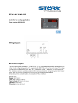
7.2 Read temperature / pressure of the
circuit 1 or circuit 2
When the “ cir1” led is lighted, press UP or Down
arrow to read all the probe values of the circuit 1.
To read temperature / pressure of the circuit 2, press
SET button during the visualization of the temperature /
pressure of the circuit 1.
Example in fig.1
Led cir1 is on: the top display shows the value of the
output evaporator temperature ( 7.8°C) of the circuit 1,
the bottom display shows Out 1. Push SET key to swap
to the circuit 2.
Example in Fig2
Led cir2 is on: the top display shows the value of the
output evaporator temperature ( 7.9°C) of the circuit 2,
the bottom display shows Out 2.
Fig.1
Fig.2
8. Programming with the “Hot key
64”
8.1 Download: how to program the Ichill
using a programmed Hot key
1. Turn off the instrument supply
2. Insert the hot key.
3. Turn on the power supply.
4. Immediately the parameters are downloaded.
During the download the regulation is locked and the
top display shows the “ doL” blinking label. At the end
of the download will appear:
“End” if the programming procedure is completely OK,
after 30seconds the regulation starts automatically.
“Err” if the programming procedure has found an
error and the parameter have not been transferred. In
this case turn off and then on the instrument supply to
repeat the operation or remove the hot key, with power
supply off, to restart the regulation.
8.2 Upload: how to copy the Ichill
parameter map into the Hot key
1. Turn on the power supply.
2. Insert the hot key.
3. Enter the function Menu.
4. Select the UPL function (on the bottom display).
5. Push SET key and immediately the instrument
starts transfer the parameters into the Hot key.

1592015870 Quick reference guide IC260_261L_D DUO FW 1.9 05-04-2016 IC260/261L/D 10/64
During the upload the regulation is locked and the top
display shows the “ UPL” blinking label. At the end of
the UPLOAD will appear:
“End” if the programming procedure is completely OK,
after 30seconds the regulation starts automatically.
“Err” if the programming procedure has found an
error and the parameter have not been transferred.
Repeat the procedure.
To exit the UPL function push the MENU key or wait the
time-out (15 sec).
9. Parameter Programming using the
keyboard
Through the instrument keyboard it is possible to enter
the parameter programming. In all the three accessible
levels the user can show and modify both value and
visibility of the parameters. To ensure an easy
navigation through the different levels the common
parameters have been named and grouped under a
family name.
The three levels of programming:
Pr1 User level
Pr2 Maintenance level
Pr3 OEM level
9.1 Password default values
Password level Pr1 = 1
Password level Pr2 = 2
Password level Pr3 = 3
Under the function Menu (to reset the Alarm Log or
the Compressor Overload) the password is 0 (see
parameter AL46)
Each password can be changed, the range is from
0 to 999.
Each parameter has two level: visibility and modify.
Therefore it can be configured as follow:
The parameter can be showed and changed.
The parameter can be showed but not
changed.
9.2 Enter the Pr1 - Pr2 - Pr3
programming levels
Pr1 LEVEL:
Push SET + DOWN together for 3 seconds, the top
display shows the PAS label and the bottom display
shows the Pr1 label. The leds cir1/cir2 are blinking (up
and down leds) to inform that you now are in PR1
programming level.
Pr2 LEVEL:
From the Pr1 level push the UP key for 2 seconds and
the bottom display will show Pr2. The top display still
shows PAS.
Pr3 LEVEL:
From the Pr2 level push the UP key for 2 seconds and
the bottom display will show Pr3. The top display still
shows PAS.
After selecting the level push the SET key and the top
display will show the 0 blinking value where to insert
the password .
Set the password level using the UP and DOWN keys
then confirm with SET key.
Dependening on the password value there will be the
different level access, if the password is wrong the
instrument shows the password value again.
ATTENTION:
for all the programming levels Pr1,2,3: the CF family (or
configuration parameters) can not be changed if the
unit is running in chiller, heat pump. The user can
check the leds #1 and #2 and if they are blinking it is
not possible to change this parameters but it is
necessary to set the unit in stand-by and then enter
the programming again.
During the defrost the dF family can’t be programmed.
9.3 How to change a parameter value
1. Push the SET + DOWN keys together for 3
seconds;
2. Select the parameter label with up and down
keys;
3. Push SET to enter the parameter value;
4. Change the value with UP or DOWN keys;
5. Push “ SET” to confirm, after some seconds the
display shows the next parameter;

1592015870 Quick reference guide IC260_261L_D DUO FW 1.9 05-04-2016 IC260/261L/D 11/64
6. Exit: Push SET + UP together when a parameter
label is displayed or wait 15seconds without
pushing a key.
NOTE: a new parameter value is confirmed also after
the 15 seconds of timeout is expired (without pushing
SET key to confirm).
9.4 Change the Password value
Pr1 LEVEL
Remember that it is necessary to know the old
password value.
1) Enter the Pr1 level
2) Select a parameter family.
3) Inside the family select the “ Pr1 - 1” , Pr1 on the
bottom display, the current password value 1 on
the top display. Push the SET key to change the
value that now is blinking.
4) Use the UP or DOWN key to insert the NEW
PASSWORD value, then push SET to confirm the
new value.
5) The top display blinks for some seconds and
then shows the next parameter.
6) Exit the programming pushing SET + UP
together or wait the timeout.
Pr2 LEVEL
Remember that it is necessary to know the old
password value.
1. Enter the Pr2 level
2. Select a parameter family.
3. Inside the family select the “ Pr2 - 2” , Pr2 on the
bottom display, the current password value 2 on
the top display. Push the SET key to change the
value that now is blinking.
4. Use the UP or DOWN key to insert the NEW
PASSWORD value, then push SET to confirm the
new value.
5. The top display blinks for some seconds and
then shows the next parameter
6. Exit the programming pushing SET + UP
together or wait the timeout.
Inside the Pr2 level it is possible to change also the
Pr1 password.
Pr3 LEVEL
Remember that it is necessary to know the old
password value.
1. Enter the Pr3 level
2. Select a parameter family.
3. Inside the family select the “ Pr3 - 3” , Pr3 on the
bottom display, the current password value “ 3”
on the top display. Push the SET key to change
the value that now is blinking.
4. Use the UP or DOWN key to insert the NEW
PASSWORD value, then push SET to confirm the
new value.
5. The top display blinks for some seconds and
then shows the next parameter
6. Exit the programming pushing SET + UP
together or wait the timeout.
Inside the Pr3 level it is possible to change also the
Pr1 and Pr2 passwords.
9.5 Move a parameter level from Pr2 to
Pr1
Enter Pr2 programming level
Select the parameter and if the led # 3 is off: the
parameter is available only in Pr2.
To show the parameter also in Pr1:
1. Keep pushed SET key;
2. Push 1 time the DOWN key and the led 3 should
be on, the parameter is now available in Pr1.
To hide the parameter in Pr1:
1. Keep pushed SET key;
2. Push 1 time the DOWN key and the led 3 should
be off, the parameter is now removed from Pr1.
3.
9.6 Move a parameter from Pr3 to Pr2 to
Pr1
Enter Pr3 programming level, here the parameter
are all visible:
Select the parameter, if all the leds are off the
parameter is available only in Pr3.
To show the parameter also in Pr2 and Pr1:
1. Keep pushed SET key;
2. Push 1 time the DOWN key and the leds 3 and 4
should be on, the parameter is now available
also in Pr2 / Pr1.
To show the parameter only in Pr2:
1. Keep pushed SET key;
2. Push 1 time the DOWN key and the leds 3 is off,
the parameter is now available also in Pr2.
To show the parameter only in Pr3:

1592015870 Quick reference guide IC260_261L_D DUO FW 1.9 05-04-2016 IC260/261L/D 12/64
1. Keep pushed SET key
2. Push 1 time the DOWN key and the leds 3 and 4
are off, the parameter is now available only in
Pr3.
3.
9.7 Visibility and Parameter value locked
To set the only visibility and lock the parameter
value it is necessary enter Pr3 programming level.
Pr1 PARAMETER VISIBILITY
Enter the Pr3 level
1. Select the parameter;
2. Keep pushed the SET key;
3. Push 1 time the MENU key and the led 3 change
from on to blinking: the parameter is visible in
Pr1 but can’t be changed.
Pr2 PARAMETER VISIBILITY
Enter the Pr3 level
1. Select the parameter;
2. Keep pushed the SET key;
3. Push 1 time the MENU key and the led 4 change
from on to blinking the parameter is visible in Pr2
but can’t be changed.
Leds 3 / 4 blinking: the parameter is visible in Pr1
and in Pr2 but in those levels now they can’t be
changed.
TO SET THE ORIGINAL TAG FOR THE PARAMETER
Pr1 / Pr2
1. Keep pushed the SET key;
2. Push one time the MENU key, the leds 3 / 4 turn
on, the parameter can be seen and modified in
Pr1 and Pr2.
10. Function Menu “ M” Key
The function Menu is composed of the following items:
1) Show and reset the alarms ALrM
2) Compressor overload alarm reset COtr
3) Show and reset the alarm log ALOG
4) Upload the parameter into the Hot Key UPL
5) Enable – disable one or the two circuits CrEn
6) Enable – disable one of the compressors COEn
7) Display the compressor discharge temperature
COdt
8) Show and reset the number of compressor
running hour Hour
9) Show and reset the number of compressor
starts-up COSn
10) Show the condensing fan speed percentage of
the proportional output Cond
11) Show the percentage of the proportional output
0 ÷ 10 Vdc Pout
12) Time counting to next defrost cycle, under heat
pump mode, dF
13) Free cooling probe and set point visualization
and outputs status (only if Free cooling is
configured FC)
14) Solar panel probe and set point visualization
and outputs status (only if solar panel is
configured) (SoL)
15) Show the probe temperatures that enabled to
control the auxiliary output uS
16) Show the probe the temperature of the remote
panels trEM
MENU FUNCTION ACCESS: Push and release
the M key.
MENU FUNCTION ACCESS: Push and release
the M key or wait the timeout (15 seconds).
With the UP or DOWN keys move inside the label list.
10.1 Alarm list: show and reset
ALrM FUNCTION
Enter the function MENU pushing M key one time
1) Use the UP or DOWN to select the AlrM label
2) Push SET key (Nothing happens if there are no
active alarm events)
3) Bottom display: alarm label code. Top display:
label rSt to reset or NO if it is not possible.
4) Use the UP or DOWN to scroll the alarm list.
5) Pushing SET when the rSt label is displayed the
corresponding alarm will be reset, then the
display shows next alarm in the list, pushing SET
again the alarm is reset and the display shows
next alarm etc. Nothing happens by pushing
SET when the label NO is displayed, in this case
push UP or DOWN to move to another alarm
label.
6) To exit the ALrM reset function push MENU one
time or wait the timeout.

1592015870 Quick reference guide IC260_261L_D DUO FW 1.9 05-04-2016 IC260/261L/D 13/64
10.2 Compressor overload alarm reset
COtr function resets the compressor overload alarm
event.
Within the COtr function all the active compressor
overload alarms are displayed in a list.
Labels involved in COtr: CO1r = compressor 1
overload reset … CO6r = compressor 6 overload
reset. ATTENTION
In the COtr function the alarm is displayed only after
the number of events per hour have reched the Par.
AL20 value, only after that number of events per hour
the alarm becomes MANUAL.
MANUAL ALARM RESET PROCEDURE
Enter Menu function
1. Use UP or DOWN key and select the COtr on the
bottom display.
2. Push SET one time, if there are active alarms the
bottom display shows the alarm label eg. CO1r
(for compressor 1) while the top display shows
the label rSt to reset the alarm or NO if the alarm
can not be reset. Use the UP or DOWN keys to
scroll all the alrm list.
3. Nothing happens by pushing SET when the
label NO is displayed.
4. Pushing SET when the rSt label is displayed the
corresponding alarm will be reset after the
password: bottom display = ArSt while the top
display = PAS.
5. Push SET and the top display blinks 0 while the
bottom shows PAS. Insert the password using UP
or DOWN key (see AL parameter family). If the
password is OK the ArSt blinks for per 3seconds,
if the password value is not correct the top
display blinks 0 while the bottom shows PAS. If
within 5 seconds no value is inserted the display
label come back to CO1r function.
6. To ex it the COtr function push MENU or wait the
timeout.
7. Repeat operation 1 – 5 to reset the other alarms.
10.3 Password for compressor overload
alarm reset
The default value is 0 to change this value enter Pr3
level under the AL parameter family
10.4 Alarm log list
ALOG FUNCTION TO SEE THE ALARM LOG
The function and the alarm codes are visible only if
there are alarm events. If many events are active at the
same time the list displayed by increasing order.
Enter the function Menu
1. Select ALOG
2. Push SET one time. Nothing happens if there are
no active alarm events.
3. The bottom display shows the alarm label, the
top display shows the a number in the range 00
to 99.
4. Use the UP or DOWN keys to scroll the list.
5. To exit the ALOG function push MENU or wait the
timeout.
10.5 Erase the Alarm log list
ALOG FUNCTION TO ERASE THE LOG LIST
1. Enter the function Menu.
2. Use the UP or DOWN keys to select ALOG on the
bottom display.
3. Push on e time the SET key.
4. Within the ALOG function select with UP or
DOWN keys, the ArSt label on the bottom
display while the top display shows PAS.
5. Push SET: the bottom display shows PAS and the
top display a blinking 0.
6. Insert the password (See parameter family AL)
7. If the password is OK the label ArST blinks for 5
seconds then the display returns to normal
condition read-out (probes).
8. If the password is not correct the display shows
PAS again. in any case is possible to scroll the
list with UP or DOWN
9. To exit push the M key one time or wait the
timeout.
10.6 Password value of the alarm list
The default value is 0 to change this value enter Pr3
level under the AL parameter family.
THE ALARM LIST CONTAINS 100 EVENTS IN A FIFO
STRUCTURE. WHEN THE MEMORY IS FULL ANY NEW
ALARM WILL ERASE THE OLDEST.

1592015870 Quick reference guide IC260_261L_D DUO FW 1.9 05-04-2016 IC260/261L/D 14/64
11. Set point modification
11.1 Read the Set Point
Push and release the SET key, the leds of the circuits
are off and the set value is displayed.
In stand-by the bottom display shows SetC (set chiller),
by pushing SET again the next label is SetH (set heat
pump ).
If the unit is running the only set displayed is related to
the running mode.
11.2 Modify the Set Point
1) Push SET key for at least 3 seconds: the leds of
the circuits are off and the set value is blinking.
2) Use the UP or DOWN key to modify the setpoint.
3) Push SET to confirm or wait the timeout
(15seconds).
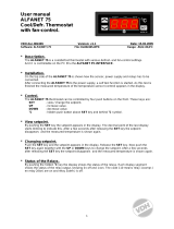
12) Installing And Mounting
Ichill 200L: panel cut out
The instrument must be mounted on vertical panel, with
panel cut-out 150x 31mm, and screwed 2 screws 3
x 2mm, in between distance 165mm. The IP65 can be
reached with the gasket RG-L (optional).
Avoid locations subject to heavy vibration, corrosive
gases or excessive dirt. The same applies to the
probes. Ensure ventilation around the instrument.
165
150
31
Ø3 x2
Plexiglass protection bottom open
Plexiglass protection top open
ICHILL 200 L FORMAT: metal front frame
Ichill 200 Din Format SERIES
IC260D - IC261D (10 DIN modules)
WARNING: all the distance show in the figure below
are expressed in mm

1592015870 Quick reference guide IC260_261L_D DUO FW 1.9 05-04-2016 IC260/261L/D 15/64
Remote keyboard Vi620: panel cut-out
The remote terminals are suitable for panel mounting,
panel cut-out 72x56 mm, and screwed with two
screws.The IP65 can be reached with the gasket
RGW-V (optional).
Fig. 1
WALL MOUNTING: use the vertical V-KIT (black, white
and grey color) as described in the following scheme:
13. Electrical Connections
The instrument is provided with:
3 removable terminal blocks MOLEX with 0.5 mm
2
wires: 16 / 8 /22 ways for digital / analogue inputs
and modulating outputs.
4 removable screw terminal block STELVIO for
2.5 mm
2
wires connection: 3 / 4 / 5 / 6 ways for the
relay outputs.
5 ways connector for TTL RS485 interface
outputs.
2 ways connector for remote panels to be
connected with the cable CAB/CJ30. The remote
panels have two terminals for 2.5 mm
2
wires.
The LW30 KIT is the complete kit with MOLEX + 3
mt wires already connected and the STELVIO
terminals.
Check the connecitons and the line voltage
before turning on the power supply.
Keep low voltage cables, such as
analogue/digital inputs/outputs and probes, away
from power cables and terminals.
Respect the maximum load current of each relay
output, in case of power loads use filtered contactors .

1592015870 Quick reference guide IC260_261L_D DUO FW 1.9 05-04-2016 IC260/261L/D 16/64
14. Table Of The Output Status In Alarm Condition
The alarm codes are made of letters and numbers to define the different typologies:.
14.1 ALARM
Alarm
Code
Alarm description
Compressor
Anti freeze
heaters
Boiler
Support
heaters
Evaporat
or Pump /
Supply
fan
Condenser
fan
Cir1 / Cir2
Auxiliary
relay
AP1
AP12
Probe PB1..Pb12
alarm
Yes (6)
Yes (1)
Yes
AEFL
Evaporator flow
alarm
Yes
Yes (boiler)
Yes
evaporat
or water
pump (3)
Yes
ACFL
Condenser flow
alarm
Yes
Yes
condense
r water
pump (3)
Yes
AHFL
Sanitary water flow
switch alarm
Yes (6)
Yes
sanitary
water
pump (3)
APFL
Solar panel flow
switch alarm
Yes (6)
Yes solar
panel
water
pump (3)
Yes
AtSF
Supply fan overload
alarm
Yes
Yes
Yes
supplay
fan
Yes
AtE1
Evaporator 1 water
pump overload
alarm
Yes (4)
Yes (boiler) (5)
Yes
evaporat
or water
pump 1
Yes
AtE2
Evaporator 2 water
pump overload
alarm
Yes (4)
Yes (boiler) (5)
Yes
evaporat
or water
pump 2
Yes
AtC1
Condenser 1 water
pump overload
alarm
Yes (4)
Yes
condense
r water
pump 1
Yes

1592015870 Quick reference guide IC260_261L_D DUO FW 1.9 05-04-2016 IC260/261L/D 17/64
AtC2
Condenser 2 water
pump overload
alarm
Yes (4)
Yes
condense
r water
pump 2
Yes
AtAS
Sanitary water pump
overload
Yes (6)
AtHS
Sanitary heaters
overload
AEP1
Evaporator 1 water
pump maintenance
AEP2
Evaporator 2 water
pump maintenance
support
ACP1
Condenser 1 water
pump maintenance
ACP2
Condenser 2 water
pump maintenance
ASAn
Sanitary water pump
maintenance
ASUn
Solar panel water
pump maintenance
ArtC
Clock alarm
Atr1
Remote keyboard n°
1 alarm
Atr2
Remote keyboard n°
2 alarm
ALc1
Generic alarm
Yes
Yes
Yes
Yes
ALc2
Generic alarm
Yes
Yes
Yes
Yes
AEE
Eeprom alarm
Yes
Yes
Yes
Yes
ACF1
ACF1
2
Configuration alarm
Yes
Yes
Yes
Yes
ArtF
Faulty clock
ArtC
Clock error
AEUn
Unloading
signalling from high
temp of. evaporator
water
ALti
Low evaporator inlet
temperature in
air/air unit
AEht
High water
temperature inlat
Yes

1592015870 Quick reference guide IC260_261L_D DUO FW 1.9 05-04-2016 IC260/261L/D 18/64
evaporator
AFr
Supplay frequence
alarm
Yes
Yes
Yes
Yes
ALSF
Phase sequence
failure
Yes
Yes
Yes
Yes
Yes
Yes
(1) = if probe configured as anti-freeze / boiler control and Ar10 = 0
(2) = if probe configured as auxiliary relay control
(3) = manual alarm procedure
(4) = compressors switched off when only 1 water pump is configured or both water pumps are in alarm
(5) = Boiler heaters off with only 1 water pump configured or with 2 pumps but both in alarm from the corresponding digita l inputs (in this case the
boiler heaters are on only with thermoregulation anti-freeze setpoint as evaporator protection function)
(6) = If the faulty probe is the regulation probe or circuit probe (condenser probe, suction probe)
14.2 ALARM: circuit alarm
Alarm
Code
Alarm description
Compress
ors
of the
circuit
(n)
Compress
ors
of the
other
circuit
Fan
condensing
of the circuit
(n)
Fan
condensing
of the other
circuit
b(n)HP
High pressure switch of the circuit (n)
Yes
Yes after 60
seconds
b(n)LP
Low pressure switch of the circuit (n)
Yes
Yes
b(n)AC
Anti-freeze in chiller of the circuit (n)
Yes
Yes
b(n)AH
Anti-freeze in heat pump of the circuit (n)
Yes
Yes
b(n)hP
High condensing pressure of the circuit (n)
Yes
Yes after 60
seconds
b(n)hP
High condensing temperature from NTC of the
circuit (n)
Yes
Yes after 60
seconds
b(n)lP
Low condensing pressure - (evaporating with
low pressure transducer) with transducer of
the circuit of the (n)
Yes
Yes
b(n)lP
Low condensing temperature NTC circuit (n)
Yes
Yes
b(n)tF
Fan overload circuit (n)
Yes
Yes
b(n)PH
Pump down alarm in stop regulation of the
circuit (n)
Yes
Yes
b(n)PL
Pump down in regulation start-up of the circuit
(n)
Yes
Yes
b(n)dF
Bad defrost circuit (n)
b(n)Cu
Unloading from condenser high temp/press of
the circuit (n)

1592015870 Quick reference guide IC260_261L_D DUO FW 1.9 05-04-2016 IC260/261L/D 19/64
b(n)Cu
Unloading from evaporator low temp/press of
the circuit (n)
Yes
Yes
b(n)rC
Recovery function disabled in circuit (n)
b(n)ds
Circuit (n) disabled from keyboard
Yes
Yes
b(n)Ac
Anti-freeze circuit (n) message in chiller
b(n)Ah
Anti-freeze circuit (n) message in heat pump
(n) identifies the circuit 1 or 2
14.3 ALARM: compressor alarm
Alarm Code
Alarm description
Compressor
(n)
Compressors not involved
C(n)HP
Compressor(n) high pressure switch
Yes
C(n)oP
Compressor(n) oil pressure switch / Oil
level switch
Yes
C(n)tr
Compressor(n) overload
Yes
C(n)dt
Compressor high discharge temperature
Yes
C(n)Pd
Compressor differential oil
Yes
C(n)dS
Compressor (n) disabled from keyboard
Yes
C(n)Mn
Compressor(n) maintenance
(n) identifies the compressor 1, 2 , 3 , 4 , 5 , 6
15. Wiring Connections
15.1 Hardware Resources: IC260L
10 relays (MAX current on the relay contacts 5(2)A 250V; MAX current in the common line of the relays 12A 250V)
18 digital inputs (free voltage)
10 analogue inputs: configurable ( 6 NTC or PTC, 4 NTC or PTC or pressure transducer 4÷20mA or ratio-metric 0÷ 5.0
Volt)
2 PWM output (to manage the condenser fan)
6 0..10V output
1 output for remote keyboard (max 2 remote panels)
1 TTL output to connect an “Hot Key 64” (parametrs programming) or to connect a XJ485CX (TTL / RS485 interface)

1592015870 Quick reference guide IC260_261L_D DUO FW 1.9 05-04-2016 IC260/261L/D 20/64
15.2 Hardware Resources: IC261L
14 relays (MAX current on the relay contacts 5(2)A 250V; MAX current in the common line of the relays 12A 250V)
18 digital inputs (free voltage)
10 analogue inputs: configurable ( 6 NTC or PTC, 4 NTC or PTC or pressure transducer 4÷20mA or ratio-metric 0÷ 5.0
Volt)
2 PWM output (to manage the condenser fan)
6 0..10V output
1 output for remote keyboard (max 2 remote panels)
1 TTL output to connect an “Hot Key 64” (parametrs programming) or to connect a XJ485CX (TTL / RS485 interface)
15.3 Hardware Resources: IC260D
10 relays (MAX current on the relay contacts 5(2)A 250V; MAX current in the common line of the relays 12A 250V)
18 digital inputs (free voltage)
10 analogue inputs: configurable ( 6 NTC or PTC, 4 NTC or pressure transducer 4÷20mA or ratio-metric 0÷ 5.0 Volt)
2 PWM output (to manage the condenser fan)
6 0..10V output
1 output for remote keyboard (max 2 remote panels)
1 TTL output to connect an “Hot Key 64” (parametrs programming)
1 RS 485 output
/