Elektron Analog Heat MKI Quick start guide
- Category
- Musical Equipment
- Type
- Quick start guide

Analog
Heat
Stereo Analog Sound Processor
Quick Guide


3
THANK YOU
Thank you for purchasing Analog Heat. The Analog Heat is a stereo analog sound processor with
many great features such as; 8 dierent analog eect circuits, an analog multimode filter, analog EQ,
and support for Elektron’s groundbreaking software suite Overbridge.
Its innovative combination of modern technology and tried and trusted ways of analog sound process-
ing lets you add sparkly brilliance, or grimy roughness, to any sound source. Samplers, drum machines,
synths, the master bus, you name it. Analog Heat is a fiery furnace destined to make your music glow.
This Quick Guide will guide you through the basic functions of this product. For more detailed informa-
tion, please see the Analog Heat User Manual that you can download on www.elektron.se.
We wish you a happy analog experience. Have fun!
- The Elektron Team
Analog Heat

4
Legal disclaimer
The information in this document is subject to change without notice and should not be construed
as a commitment by Elektron. Elektron assumes no responsibility for any errors that may appear
in this document. Elektron may also make improvements and/or changes in the products and pro-
grams described in this document at any time without notice. In no event shall Elektron be liable
for any special, indirect, or consequential damages or any damages whatsoever resulting from
loss of use, data, or profits, whether in an action of contract, negligence, or other action, arising
out of or in connection with the use or performance of this information.

5
FCC compliance statement
This device complies with part 15 of the FCC rules. Operation is subject to the following two con-
ditions: (1) This device may not cause harmful interference, and (2) this device must accept any
interference received, including interference that may cause undesired operation.
NOTE: This equipment has been tested and found to comply with the limits for a Class B digital
device, pursuant to Part 15 of the FCC Rules. These limits are designed to provide reasonable
protection against harmful interference in a residential installation. This equipment generates,
uses and can radiate radio frequency energy and, if not installed and used in accordance with
the instructions, may cause harmful interference to radio communications. However, there is no
guarantee that interference will not occur in a particular installation. If this equipment does cause
harmful interference to radio or television reception, which can be determined by turning the
equipment o and on, the user is encouraged to try to correct the interference by one or more of
the following measures:
• Reorient or relocate the receiving antenna.
• Increase the separation between the equipment and receiver.
• Connect the equipment into an outlet on a circuit dierent from that to which the receiver is
connected.
• Consult the dealer or an experienced radio/TV technician for help.
Canada
This Class B digital apparatus complies with Canadian ICES-003.
Cet appareil numérique de la classe B est conforme à la norme NMB-003
European Union regulation compliance statement
This product has been tested to comply with the Low Voltage Directive 2006/95/EC and the
Electromagnetic Compatibility Directive 2004/108/EC. The product meets the requirements of
RoHS 2 Directive 2011/65/EU.
Your product must be disposed of properly according to local laws and regulations.

6
IMPORTANT SAFETY INSTRUCTIONS
1. Do not use the unit near water.
2. Never use aggressive cleaners on the casing or on the LCD screen. Remove dust, dirt and finger-
prints with a soft, dry and non-abrasive cloth. More persistent dirt can be removed with a slightly
damp cloth using only water. Disconnect all cables before doing this. Only reconnect them when
the product is safely dry.
3. Install in accordance with the manufacturer’s instructions. Make sure you place the unit on a stable
surface before use.
4. Connect the unit to an easily accessible electrical outlet close to the unit.
5. When transporting the unit, preferably use accessories recommended by the manufacturer or the
box and padding the unit was originally shipped in.
6. Do not install near any heat sources such as radiators, heat registers, stoves, or any other
appliance (including amplifiers) emitting heat.
7. Do not block the ventilation holes located on the bottom of the enclosure of the unit.
8. This product, in combination with an amplifier and speakers or headphones, is capable of producing
sound levels that can cause permanent hearing loss. Do not operate for a long period of time at a
high volume level or at a level that is uncomfortable.
9. Protect the power cord from being walked on or pinched particularly at plugs, convenience
receptacles, and the point where they exit from the unit.
10. Use attachments/accessories specified by the manufacturer.
11. Unplug this unit during lightning storms or when it is not used for an extended time.
12. Refer all servicing to qualified service technicians. Servicing is required when the unit has been
damaged in any way, liquid has been spilled or objects have fallen into the unit, the unit has been
exposed to rain or moisture, does not operate normally, or has been dropped.

7
WARNING!
TO REDUCE THE RISK OF FIRE, ELECTRICAL SHOCK OR PRODUCT DAMAGE
• Do not expose the unit to rain, moisture, dripping or splashing and also avoid placing objects filled
with liquid, such as vases, on the unit.
• Do not expose the unit to direct sunlight, nor use it in ambient temperatures exceeding 35°C as this
can lead to malfunction.
• Do not open the casing. There are no user repairable or adjustable parts inside. Leave service and
repairs to trained service technicians only.
• Do not exceed the limitations specified in the Electrical specifications.
SAFETY INSTRUCTIONS FOR THE POWER ADAPTER ELEKTRON PSU-3B
• The adapter is not safety grounded and may only be used indoors.
• To ensure good ventilation for the adapter, do not place it in tight spaces. To prevent risk of electric
shock and fire because of overheating, ensure that curtains and other objects do not prevent
adapter ventilation.
• Do not expose the power adapter to direct sunlight, nor use it in ambient temperatures exceeding
40°C.
• Connect the adapter to an easily accessible electrical outlet close to the unit.
• The adapter is in standby mode when the power cord is connected. The primary circuit is always
active as long as the cord is connected to the power outlet. Pull out the power cord to completely
disconnect the adapter.
• In the EU, only use CE approved power cords.

8
TABLE OF CONTENTS
. INTRODUCTION .............................................................................................................................................9
. CONVENTIONS IN THIS MANUAL ................................................................................................................................. 9
. PANEL LAYOUT AND CONNECTIONS ...................................................................................................10
. FRONT PANEL CONTROLS............................................................................................................................................ 10
. REAR PANEL CONNECTIONS ......................................................................................................................................12
. FIRST STEPS WITH THE ANALOG HEAT ..............................................................................................13
3. CONNECTING THE UNIT ................................................................................................................................................... 13
. SETTING THE INPUT SENSITIVITY LEVEL ...........................................................................................................13
. SETUP EXAMPLES .............................................................................................................................................................. 14
. SIGNAL FLOW ..............................................................................................................................................15
. AUDIO SIGNAL FLOW ......................................................................................................................................................... 15
. MODULATION SIGNAL FLOW .......................................................................................................................................16
. THE USER INTERFACE ..............................................................................................................................17
. PRESETS .................................................................................................................................................................................... 17
. ACTIVE MODE .......................................................................................................................................................................17
. EFFECT CIRCUITS ..............................................................................................................................................................17
. FILTER TYPE ...........................................................................................................................................................................18
. EQUALIZER .............................................................................................................................................................................18
. DRIVE ..........................................................................................................................................................................................18
. WET LEVEL ..............................................................................................................................................................................19
. DRY/WET ..................................................................................................................................................................................19
. SETTINGS MENU .................................................................................................................................................................19
. PARAMETER PAGES ........................................................................................................................................................19
. PARAMETER EDITING ......................................................................................................................................................19
. LCD SCREEN TITLE BAR ..............................................................................................................................................20
. OVERBRIDGE ......................................................................................................................................................................20
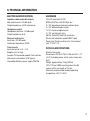
. TECHNICAL INFORMATION ..................................................................................................................... 21
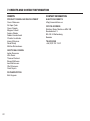
. CREDITS AND CONTACT INFORMATION ............................................................................................ 22

9
. INTRODUCTION
. CONVENTIONS IN THIS MANUAL
We have used the following conventions throughout the manual:
Key names are written in upper case, bold style and within brackets. For instance, the key labeled
“Settings” on the main panel is written as [SETTINGS].
Knobs are written in upper case, bold, italic letters. For instance, the knob “Frequency” is called
FREQUENCY.
LED indicators like the Active LED are written like this: <ACTIVE>.
Menu names are written in upper case letters. The AMP menu is an example of that.
Parameter names and certain menu options where settings can be made or actions performed are
written in bold, upper case letters. For example, ATTACK.
Upper case letters are used for parameter setting alternatives, for example OFF.
Messages visible on the screen are written in upper case letters with quotation marks. For example,
“INPUT LEVEL TOO HIGH!”.

10
. PANEL LAYOUT AND CONNECTIONS
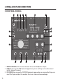
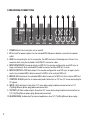
. FRONT PANEL CONTROLS
12
14
1119
9
8
10
7
13
15161718
654321
20
21
1. MASTER VOLUME sets the master volume for the L/R and Headphones outputs.
2. [AMP] key accesses the AMP parameter page where you can set things such as drive amount
and the volume of the preset.
3. [FILTER/EQ] key accesses the FILTER/EQ parameter pages where you, among other things, can
select filter types and adjust the equalizer. Press twice to access the second page.

11
4. [ENV] key accesses the ENV parameter pages where you adjust the settings for the envelope
generator/envelope follower. Press twice to access the second page.
5. [LFO] key accesses the LFO parameter pages where you set all things related to the Low
Frequency Oscillator. Press twice to access the second page.
6. LCD screen.
7. PRESET/DATA Used for preset management and data entry.
8. [YES] key is used for entering sub-menus, selecting and confirming.
9. [NO] key is used for exiting the current menu, backing to a higher level menu and negating.
10. DATA ENTRY knobs. Used to set parameter values. For more information, please see "5.11 PARAM-
ETER EDITING" on page 19.
11. LOW and HIGH adjusts the amount of low-end and high-end frequency content.
12. <FILTER TYPE> LEDs that indicate the current type of filter and also if the filter is on or not.
13. RESONANCE sets the resonance of the filter.
14. [FILTER TYPE] selects between the dierent filter types. Also, pressing both keys at the same time
toggles the filter on and o.
15. FREQUENCY sets the filter’s cuto frequency.
16. DRY/WET sets the balance between the unprocessed (dry) signal and the processed (wet) signal.
17. WET LEVEL sets the level of the processed (wet) signal.
18. DRIVE controls the amount of drive. This will increase the eect of the selected circuit type,
typically resulting in more distortion.
19. CIRCUIT SELECTOR chooses between the eight dierent types of eect circuits.
20. [SETTINGS] key accesses the SETTINGS menu. Both preset-specific settings and global settings
are found in this menu.
21. [ACTIVE] toggles the eect between active and bypassed.

12
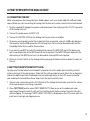
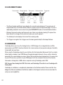
. REAR PANEL CONNECTIONS
1 2 3 4 5 6 7 8 9 10
1. POWER, Switch for turning the unit on and o.
2. DC In, Input for power supply. Use the included PSU-3b power adapter connected to a power
outlet.
3. USB, For connecting the unit to a computer. For MIDI control or Overbridge use. Connect to a
computer host using the included A to B USB 2.0 connector cable.
4. MIDI THRU/SYNC B, Forwards data from MIDI IN. Can also be configured to send DIN sync to
legacy instruments. Use standard MIDI cable to connect another MIDI unit in chain.
5. MIDI OUT/SYNC A, MIDI data output. Can also be configured to send DIN sync to legacy instru-
ments. Use standard MIDI cable to connect to MIDI In of an external MIDI unit.
6. MIDI IN, MIDI data input. Use standard MIDI cable to connect to MIDI Out of an external MIDI unit.
7. CONTROL IN A/B Inputs for an expression pedal, footswitch, or CV. Use 1/4” mono phone plug for
CV signals.
8. INPUT L/R, Audio inputs. Use either 1/4” mono phone plug (unbalanced connection) or 1/4”
(Tip/Ring/Sleeve) phone plug (balanced connection).
9. OUTPUT L/R, Main audio outputs. Use either 1/4” mono phone plug (unbalanced connection) or
1/4” (Tip/Ring/Sleeve) phone plug (balanced connection).
10. HEADPHONES, Audio output for stereo headphones. Use 1/4” (Tip/Ring/Sleeve) phone plug.

13
. FIRST STEPS WITH THE ANALOG HEAT
3. CONNECTING THE UNIT
Make sure you place the Analog Heat on a stable support, such as a sturdy table with sucient cable
space. Before you start connecting the Analog Heat to other units, make sure all units are switched o.
1. Plug the supplied DC adapter to a power outlet and connect the small plug to the 12 V DC connector
of the Analog Heat unit.
2. Connect the audio source to INPUT L/R.
3. Connect the OUTPUT L/R from the Analog Heat to your mixer or amplifier.
4. To process sound and/or control the Analog Heat from a computer, connect a USB cable between
the computer and the USB connector of the Analog Heat. You must also download and install the
Overbridge Suite that is used for these actions.
5. If you want to use MIDI to control the Analog Heat, connect the MIDI OUT port of the device you
wish to send data from to the MIDI IN port of the Analog Heat. The MIDI THRU port duplicates the
data arriving at the MIDI IN port, so it can be used for chaining MIDI units together.
6. Switch on all units. Switch on the Analog Heat by pressing the Power switch located at the back of
the unit.
. SETTING THE INPUT SENSITIVITY LEVEL
To make sure the Heat distorts as intended it is important to set the audio input sensitivity so that it
matches the level of the sound source. (Note that the settings made here only aects the analog input,
and not the digital input from Overbridge.) Use the audio input meter on the LCD screen to monitor
your audio input level and follow these steps to set the input sensitivity level:
1. Connect your sound source to the IN L/R inputs of the Analog Heat and make sure that the volume
of the sound source is as strong as possible.
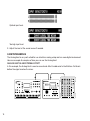
2. Press [SETTINGS] and the select INPUT SENSITIVITY. Keep an eye on the audio input meter
and change the input sensitivity until you find a setting where the bar reaches the vertical line but
without clipping. The message “INPUT LEVEL TOO HIGH” is displayed on the LCD screen when the
input level is too high, and clipping occurs.

14
Optimal input level.
Too high input level.
3. Adjust the level at the sound source if needed.
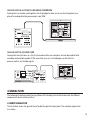
. SETUP EXAMPLES
The Analog Heat is very well suited for use in both an analog setup and in a more digital environment.
Here are a couple of examples of how you can use the Analog Heat.
ANALOG HEAT AS AN EXTERNAL EFFECT
In this example, the Analog Heat is used as an external eect to add color to the Elektron Octatrack
before the signal reaches the mixer.

15
ANALOG HEAT AS A VST/AU PLUGIN USING OVERBRIDGE
Analog Heat can also be used together with Overbridge to allow you to use the Analog Heat as a
plug-in for analog distortion processing in your DAW.
ANALOG HEAT AS A SOUND CARD
Analog Heat also functions as a 2 in/2 out sound card for your computer and can be used for both
recording and monitoring audio. At the same time you can, via Overbridge, use the eect to
process another set of audio signals.
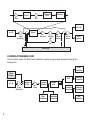
. SIGNAL FLOW
The following illustrations show the signal flows of the Analog Heat and illustrates how the dierent
components interact with each other.
. AUDIO SIGNAL FLOW
This illustration shows the general flow of audio through the Analog Heat. The complete signal chain
is in stereo.

16
In L/R
Input
Sensitivity
Eect
Wet level Dry/Wet
Mix
Preset
Volume
Master
Volume
Out L/R
Head-
phones
Circuit
DirtDrive
Multi-mode
Filter
Equalizer
Overbridge
Bypass
. MODULATION SIGNAL FLOW
This illustration shows the flow of how modulation signals are generated and routed through the
Analog Heat.
In L/R
Input
Sensitivity
Bandpass
Filter
Envelope
Follower
Gain
Filter
Modulation
Modulation
Destination
Compar-
ator
LFO
Modulation
Destination
Modulation
Destination
Trig
Filter
Modulation
Filter
Modulation
Envelope
Generator
Over-
bridge

17
. THE USER INTERFACE
. PRESETS
The Analog Heat has 128 preset slots where you can store your presets. Preset slot 000 is an INIT
preset with default values. Note that, when switching o the power to your Heat, any changes to the
currently active preset will be lost unless the preset is first saved. There is an indicator (next to the
preset number) on the LCD screen showing when changes have been made to the preset. For more
information, please see "5.12 LCD SCREEN TITLE BAR" on page 20.
LOADING A PRESET
1. Turn PRESET/DATA to select a preset.
2. Press PRESET/DATA or [YES] to load the preset.
SAVING A PRESET
1. Press and hold PRESET/DATA for two seconds. The selected preset now starts to blink to illus-
trate that you are about to overwrite the preset position.
2. Turn PRESET/DATA to select the preset slot to where you want to save your sound, and then
press [YES].
3. Turn PRESET/DATA to the character you wish to edit. Press and hold [SETTINGS] and then turn
PRESET/DATA to move the cursor to the desired character and select it by releasing [SET-
TINGS]. To delete a character, turn PRESET/DATA to move the cursor to highlight the character
after the one you wish to delete, then press and hold [SETTINGS] and press [NO] twice.
4. Press [YES] to save the preset.
. ACTIVE MODE
Active Mode is toggled on and o by pressing [ACTIVE]. If the Analog Heat is not in Active Mode,
the eect is bypassed. The <ACTIVE> LED indicates if the eect is active or not. You can also use a
Footswitch to toggle the Active Mode. You also have the option to set if you want the Analog Heat to
start in active mode or not when you turn it on.
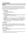
. EFFECT CIRCUITS
You can use the CIRCUIT SELECTOR to choose between 8 dierent types of eect circuits for a wide
variety of drive and distortion sounds.
• CLEAN BOOST
Makes the signal louder. When fully driven, it sounds similar to overdriving old mixers. Use for mini-
mal distortion or when you only want to use the filter and EQ.

18
• SATURATION
This circuit is reminiscent of classic tape saturation. Wooly and warm.
• ENHANCEMENT
Adding tube-like glow and sheen to a track or loop.
• MID DRIVE
Mid-range focused overdrive with a solid and distinct body.
• ROUGH CRUNCH
Gritty, worn and gnarly character. Full of flavor.
• CLASSIC DIST
Pleasantly distorts upper mid-range frequencies. Ideal for acid bass lines.
• ROUND FUZZ
Adds a lot of harmonics and alters the signal in interesting and often unpredictable ways.
• HIGH GAIN
Probably the most aggressive of all the circuits. Very maxed out!
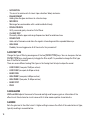
. FILTER TYPE
Change the type of filter by pressing one of the two [FILTER TYPE] keys. You can also press the two
[FILTER TYPE] keys simultaneously to toggle the filter on/o. It is possible to change the filter type
even if the filter is turned o.
There are seven dierent analog filter types in the Analog Heat to help to shape the sound.
• LOW PASS 2 (two-pole, 12 dB per octave)
• LOW PASS 1 (one-pole, 6 dB per octave)
• BAND PASS
• HIGH PASS 1 (one-pole, 6 dB per octave)
• HIGH PASS 2 (two-pole, 12 dB per octave)
• BAND STOP
• PEAK
. EQUALIZER
LOW and HIGH adjusts the amount of low-end and high-end frequency gain or attenuation of the
eect circuit. Each character circuit comes with its tailor-made equalizer characteristics.
. DRIVE
Sets the gain level in the eect circuit. A higher setting increases the eect of the selected circuit type,
typically resulting in more distortion.

19
. WET LEVEL
Sets the level of the signal coming from the eect. It is applied before the DRY/WET mix. It is used to
match the level of the dry signal for easy mixing of the two.
. DRY/WET
Sets the mix between the clean signal and the signal that is aected by the eect.
. SETTINGS MENU
Press [SETTINGS] to access the SETTINGS menu.
Scroll through the list of settings by using the PRESET/DATA knob. Open a highlighted menu by press-
ing the PRESET/DATA knob or [YES]. To change the settings in the menus, first press, and then turn
the PRESET/DATA knob.
. PARAMETER PAGES
Access the parameter pages by pressing the corresponding key [AMP], [FILTER/EQ], [ENV], and
[LFO]. There are two pages associated with each key (AMP has only one page). You can access the
secondary pages by pressing the [PARAMETER] key a second time.
. PARAMETER EDITING
The four DATA ENTRY knobs are used to change the parameter values that are shown on the LCD
screen. (Some parameters also have dedicated knobs on the panel.) The physical location of the
knobs on the front panel correspond to the layout of the parameters on the screen.
• The parameters will be adjusted in larger increments if you press down the DATA ENTRY knob
while turning it. This makes it much quicker to sweep through a whole parameter range.
• Press [SETTINGS] + turn DATA ENTRY knob to quantize the parameter value to integers.
• Press DATA ENTRY knob + [NO] to reset the parameter to the default value.
• Press [PARAMETER] key + [NO] to reset the selected parameter group to default values.
• Use the [NO] key to exit an active menu, back to a higher level menu and to negate.

20
. LCD SCREEN TITLE BAR
Preset number Preset nameChange indicator Audio input meter Trigger icon
• The Preset number and Preset name displays the currently selected preset. If you push one of
the parameter keys, the title bar briefly shows the name of the active parameter page. This text is
replaced by parameter names when turning the DATA ENTRY knobs or the dedicated controllers.
• Between the preset number and the preset name, there is an indicator showing if the preset has
been altered. (i.e. changes that may be lost unless you save the preset.)
• The Audio input meter displays the level of the incoming audio.
• The Trigger icon signals that a trigger event has been generated by the Envelope Follower.
. OVERBRIDGE
Overbridge allows you to use the Analog Heat as a VST/AU plug-in for analog distortion and filter
processing in your DAW. It also has a librarian for a clear overview of your presets and gives the ability
to load, edit, and save them.
When using the Overbridge setup, the user interface for the Analog Heat will present itself as a clearly
laid out plug-in window in your DAW. Browse through and organize presets. Access, edit or automate
parameters for sound shaping on screen. Always find your device preset parameters in the same state
as you left them when you return to your DAW project, with the convenient total recall functionality.
You need an Analog Heat, a USB cable, a computer running Overbridge, and a DAW.
N.B. You must have Analog Heat OS 1.02 or later, and Overbridge 1.15 or later to run Overbridge with
Analog Heat.
Overbridge is available as a complimentary download on the Elektron website. Please read the Over-
bridge User Manual (available on the Elektron website in the Support section) to learn more about its
setup, uses and capabilities.
Page is loading ...
Page is loading ...
Page is loading ...
Page is loading ...
-
 1
1
-
 2
2
-
 3
3
-
 4
4
-
 5
5
-
 6
6
-
 7
7
-
 8
8
-
 9
9
-
 10
10
-
 11
11
-
 12
12
-
 13
13
-
 14
14
-
 15
15
-
 16
16
-
 17
17
-
 18
18
-
 19
19
-
 20
20
-
 21
21
-
 22
22
-
 23
23
-
 24
24


Elektron Analog Heat MKI Quick start guide
- Category
- Musical Equipment
- Type
- Quick start guide
Ask a question and I''ll find the answer in the document
Finding information in a document is now easier with AI
Related papers
-
Elektron Analog Heat MKI User manual
-
-
-
-
-
-
-
-
-
Other documents
-
DigiTech Boneshaker Owner's manual
-
Spectrum Industries 96501B User manual
-
Erica Synths Acidbox III User manual
-
Electro-Harmonix Big Muff Ultimate Harmonic Distortionsustain Device User guide
-
-
DigiTech Meatbox Owner's manual
-
Intermetro LEC9800 Installation guide
-
Metro L01-492 Operating instructions
-
United Nursery 21191 User manual