
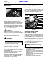
Cover photo may show optional equipment
not supplied with standard unit.
© Copyright 2008 Printed
Read the Operator’s manual entirely. When
you see this symbol, the subsequent
instructions and warnings are serious - follow
without exception. Your life and the lives of
others depend on it!
!
Table of Contents
ZT60 & ZT72 Zero Turning Radius Mowers
Riding Mowers Accu-Z®
26689
357-103M
Operator’s Manual
8/26/08

ZT60 & ZT72 Zero Turning Radius Mowers Riding Mowers Accu-Z® 357-103M 8/26/08
Land Pride
Table of Contents
©Copyright 2008 All rights Reserved
Land Pride provides this publication “as is” without warranty of any kind, either expressed or implied. While every precaution has been taken in the preparation of this manual, Land
Pride assumes no responsibility for errors or omissions. Neither is any liability assumed for damages resulting from the use of the information contained herein. Land Pride reserves
the right to revise and improve its products as it sees fit. This publicationdescribes the state of this product at the time of its publication, and may not reflect the product in the future.
Land Pride is a registered trademark.
All other brands and product names are trademarks or registered trademarks of their respective holders.
Printed in the United States of America.
Table of Contents
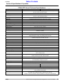
Important Safety Information . . . . . . . . . . . . . 1
Safety at All Times . . . . . . . . . . . . . . . . . . . . . . . . . . 1
Safety Labels . . . . . . . . . . . . . . . . . . . . . . . . . . . . . . 4
Introduction . . . . . . . . . . . . . . . . . . . . . . . . . . . 8
Application . . . . . . . . . . . . . . . . . . . . . . . . . . . . . . . 8
Using This Manual . . . . . . . . . . . . . . . . . . . . . . . . . 8
Terminology . . . . . . . . . . . . . . . . . . . . . . . . . . . . . 8
Definitions . . . . . . . . . . . . . . . . . . . . . . . . . . . . . . 8
Owner Assistance . . . . . . . . . . . . . . . . . . . . . . . . . 8
Serial Number Plate . . . . . . . . . . . . . . . . . . . . . . . 9
Further Assistance . . . . . . . . . . . . . . . . . . . . . . . . 9
Section 1: Assembly & Set-up . . . . . . . . . . . 10
Uncrating Instructions . . . . . . . . . . . . . . . . . . . . . 10
Control Lever Assembly . . . . . . . . . . . . . . . . . . . . 10
Seat Assembly . . . . . . . . . . . . . . . . . . . . . . . . . . . 10
Discharge Chute Assembly . . . . . . . . . . . . . . . . .11
Hitch Plate Assembly . . . . . . . . . . . . . . . . . . . . . . 11
Electrical Cable Connection . . . . . . . . . . . . . . . . . 11
Engine Preparations . . . . . . . . . . . . . . . . . . . . . . 12
Remove Mower From Crate Floor . . . . . . . . . . . .12
Section 2: Operating Procedures . . . . . . . . 13
Mower Features . . . . . . . . . . . . . . . . . . . . . . . . . . 13
Operating Check List . . . . . . . . . . . . . . . . . . . . . . 14
Instrumentation . . . . . . . . . . . . . . . . . . . . . . . . . . 14
Engine Oil Pressure Light . . . . . . . . . . . . . . . . . 14
Hour Meter . . . . . . . . . . . . . . . . . . . . . . . . . . . . . 14
Controls . . . . . . . . . . . . . . . . . . . . . . . . . . . . . . . . 14
Ignition Switch . . . . . . . . . . . . . . . . . . . . . . . . . . 14
Throttle . . . . . . . . . . . . . . . . . . . . . . . . . . . . . . . 14
Choke . . . . . . . . . . . . . . . . . . . . . . . . . . . . . . . . 15
Blade Engagement Switch . . . . . . . . . . . . . . . . . 15
Left/Right Fuel Tank Valve . . . . . . . . . . . . . . . . . 15
Control Levers . . . . . . . . . . . . . . . . . . . . . . . . . . 15
Deck Lift Pedal . . . . . . . . . . . . . . . . . . . . . . . . . . 16
Safety Start Interlock System . . . . . . . . . . . . . . . .16
Engine Starting . . . . . . . . . . . . . . . . . . . . . . . . . .16
Driving the Mower . . . . . . . . . . . . . . . . . . . . . . . . 17
Moving Mower with Stalled Engine . . . . . . . . . . . 18
Safe Operating Instructions . . . . . . . . . . . . . . . . . 19
Mower Deck Operation . . . . . . . . . . . . . . . . . . . . 21
General Operating Information . . . . . . . . . . . . . . 21
Section 3: Adjustments . . . . . . . . . . . . . . . . 23
Torque Values . . . . . . . . . . . . . . . . . . . . . . . . . . . 23
Neutral Creep Adjustment . . . . . . . . . . . . . . . . . .23
Control Lever Stops . . . . . . . . . . . . . . . . . . . . . . . 24
Steering Dampener Adjustment . . . . . . . . . . . . . . 25
Park Brake Adjustment . . . . . . . . . . . . . . . . . . . .25
Adjusting the Park Brake Lever Arm . . . . . . . . . 26
Seat Adjustment . . . . . . . . . . . . . . . . . . . . . . . . . 27
Upper Control Lever Adjustments . . . . . . . . . . . . 27
Forward Travel Adjustment . . . . . . . . . . . . . . . . 27
Ground Drive Belt Adjustment . . . . . . . . . . . . . . . 28
Deck Drive Belt Adjustment . . . . . . . . . . . . . . . . .28
Deck Leveling & Height Adjustment . . . . . . . . . . .29
Deck Level Adjustments . . . . . . . . . . . . . . . . . . .29
Deck Cutting Height Adjustment . . . . . . . . . . . . .30
Anti-Scalp Rollers . . . . . . . . . . . . . . . . . . . . . . . .31
Front Axle Pivot . . . . . . . . . . . . . . . . . . . . . . . . . .31
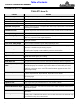
Section 4: Options & Accessories . . . . . . . . 32
Roll Over Protection System (ROPS) . . . . . . . . . .32
Folding Soft Top Canopy . . . . . . . . . . . . . . . . . . .32
Snow Plow . . . . . . . . . . . . . . . . . . . . . . . . . . . . . .32
Light Kit . . . . . . . . . . . . . . . . . . . . . . . . . . . . . . . .32
Screw Jack . . . . . . . . . . . . . . . . . . . . . . . . . . . . . .33
Mulching Kit . . . . . . . . . . . . . . . . . . . . . . . . . . . . .33
Grass Catcher . . . . . . . . . . . . . . . . . . . . . . . . . . .33
Section 5: Maintenance & Lubrication . . . . . 34
Maintenance . . . . . . . . . . . . . . . . . . . . . . . . . . . .34
Torque Values . . . . . . . . . . . . . . . . . . . . . . . . . . .34
Maintenance Schedule . . . . . . . . . . . . . . . . . . . . .35
Maintenance Locations . . . . . . . . . . . . . . . . . . . .36
Tires . . . . . . . . . . . . . . . . . . . . . . . . . . . . . . . . . . .38
Electrical System . . . . . . . . . . . . . . . . . . . . . . . . .38
Hydrostatic Drive System . . . . . . . . . . . . . . . . . . .39
Hydraulic Oil Level Check . . . . . . . . . . . . . . . . . .39
Hydraulic Oil and Filter Change . . . . . . . . . . . . . .39
Fuel System . . . . . . . . . . . . . . . . . . . . . . . . . . . . .41
Fuel Filter . . . . . . . . . . . . . . . . . . . . . . . . . . . . . . .41
Draining The Fuel Tank . . . . . . . . . . . . . . . . . . . .42
General Engine Maintenance . . . . . . . . . . . . . . . .42
Engine Oil and Oil Filter . . . . . . . . . . . . . . . . . . . .42
Oil Check . . . . . . . . . . . . . . . . . . . . . . . . . . . . . . .42
Engine Air Filter . . . . . . . . . . . . . . . . . . . . . . . . . .43
Engine Air Filter Handling . . . . . . . . . . . . . . . . . .44
Belt Replacement . . . . . . . . . . . . . . . . . . . . . . . . .45
Deck Belt Replacement Instructions . . . . . . . . . .45
Ground Belt Replacement Instructions . . . . . . . .46
Mower Blade Maintenance . . . . . . . . . . . . . . . . . .47
Storage . . . . . . . . . . . . . . . . . . . . . . . . . . . . . . . .48
Preparation of Engine for Storage . . . . . . . . . . . .48
New Season Preparation . . . . . . . . . . . . . . . . . . .49
Lubrication Points . . . . . . . . . . . . . . . . . . . . . . . .50
Deck Lift Pivot Points . . . . . . . . . . . . . . . . . . . . .50
Left Blade Spindle . . . . . . . . . . . . . . . . . . . . . . . .50
Right Blade Spindle . . . . . . . . . . . . . . . . . . . . . . .50
Center Blade Spindle . . . . . . . . . . . . . . . . . . . . .51
Front Axle Center Pivot . . . . . . . . . . . . . . . . . . . .51
Caster Wheel Bearing Zerk . . . . . . . . . . . . . . . . .51
Section 6: Specifications & Capacities . . . . . 52
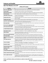
Section 7: Features and Benefits . . . . . . . . . 54
Section 8: Troubleshooting . . . . . . . . . . . . . . 56
Section 9: Appendix . . . . . . . . . . . . . . . . . . . 58
Torque Values Chart . . . . . . . . . . . . . . . . . . . . . .58
Warranty . . . . . . . . . . . . . . . . . . . . . . . . . . . . . . .59

1
Important Safety Information
8/26/08 ZT60 & ZT72 Zero Turning Radius Mowers Riding Mowers Accu-Z® 357-103M
Land Pride Table of Contents
Important Safety Information
▲
These are common practices that may or may not be applicable to the products described in
this manual.
Safety at All Times
Thoroughly read and understand
the instructions given in this
manual before operation. Refer to
the “Safety Label” section, read
all instructions noted on them.
Do not allow anyone to operate
this equipment who has not fully
read and comprehended this
manual and who has not been
properly trained in the safe
operation of the equipment.
▲Operator should be familiar with
all functions of the unit.
▲Operate implement from the
driver’s seat only.
▲Do not leave equipment
unattended with engine running.
▲Dismounting from a moving
mower could cause serious injury
or death.
▲Do not stand between the mower
and implement during hitching.
▲Keep hands, feet, and clothing
away from power-driven parts.
▲Wear snug fitting clothing to avoid
entanglement with moving parts.
▲Watch out for wires, trees, etc.,
when raising implement. Make
sure all persons are clear of
working area.
▲Turning mower too tight may
cause implement to ride up on
wheels. This could result in injury
or equipment damage.
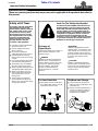
!Look For The Safety Alert Symbol
The SAFETY ALERT SYMBOL indicates there is a
potential hazard to personal safety involved and
extra safety precaution must be taken. When you
see this symbol, be alert and carefully read the
message that follows it. In addition to design and
configuration of equipment, hazard control and
accident prevention are dependent upon the
awareness, concern, prudence and proper training
of personnel involved in the operation, transport,
maintenance and storage of equipment.
Be Aware of
Signal Words
A Signal word designates a degree or
level of hazard seriousness. The
signal words are:
Indicates an imminently hazardous
situation which, if not avoided, will
result in death or serious injury. This
signal word is limited to the most
extreme situations, typically for
machine components that, for
functional purposes, cannot be
guarded.
!DANGER
Indicates a potentially hazardous
situation which, if not avoided, could
result in death or serious injury, and
includes hazards that are exposed
when guards are removed. It may also
be used to alert against unsafe
practices.
Indicates a potentially hazardous
situation which, if not avoided, may
result in minor or moderate injury. It
may also be used to alert against
unsafe practices.
!WARNING
!CAUTION
For Your Protection
▲Thoroughly read and understand
the “Safety Label” section, read all
instructions noted on them.
Shutdown and Storage
▲Lower machine to ground, put
mower in park, turn off engine, and
remove the key.
▲Detach and store implements in a
area where children normally do
not play. Secure implement by
using blocks and supports.
OFF
REMOVE

2
Important Safety Information
ZT60 & ZT72 Zero Turning Radius Mowers Riding Mowers Accu-Z® 357-103M 8/26/08
Land Pride
Table of Contents
These are common practices that may or may not be applicable to the products described in
this manual.
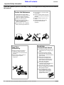
Practice Safe Maintenance
▲Understand procedure before
doing work. Use proper tools and
equipment, refer to Operator’s
Manual for additional information.
▲Work in a clean dry area.
▲Put mower in park, turn off
engine, and remove key before
performing maintenance.
▲Allow mower to cool completely
before performing maintenance.
▲Do not grease or oil mower while
in operation.
▲Inspect all parts. Make sure parts
are in good condition and installed
properly.
▲Remove buildup of grease, oil or
debris.
▲Remove all tools and unused
parts from mower before
operation.
Keep Riders
Off Machinery
▲Riders obstruct the operator’s
view, they could be struck by
foreign objects or thrown from the
machine.
▲Never allow children under 16
years of age to operate
equipment.
Avoid High
Pressure Fluids Hazard
▲Escapingfluid under pressurecan
penetratethe skincausing serious
injury.
▲Avoid the hazard by relieving
pressure before disconnecting
hydraulic lines or performing work
on the system.
▲Make sure all hydraulic fluid
connections are tight and all
hydraulic hoses and lines are in
good condition before applying
pressure to the system.
▲Use a piece of paper or
cardboard, NOT BODY PARTS, to
check for suspected leaks.
▲Wear protective gloves and safety
glasses or goggles when working
with hydraulic systems.
▲If an accident occurs, see a
doctor immediately. Any fluid
injected into the skin must be
treated within a few hours or
gangrene may result.

3
Important Safety Information
8/26/08 ZT60 & ZT72 Zero Turning Radius Mowers Riding Mowers Accu-Z® 357-103M
Land Pride Table of Contents
Prepare for Emergencies
▲Be prepared if a fire starts.
▲Keep a first aid kit and fire
extinguisher handy.
▲Keep emergency numbers for
doctor, ambulance, hospital and
fire department near phone.
911
Wear
Protective Equipment
▲Protectiveclothingand equipment
should be worn.
▲Wear clothing and equipment
appropriate for the job. Avoid
loose fitting clothing.
▲Prolonged exposure to loud noise
can cause hearing impairment or
hearing loss. Wear suitable
hearing protection such as
earmuffs or earplugs.
▲Operating equipment safely
requires the full attention of the
operator. Avoid wearing radio
headphones while operating
machinery.
These are common practices that may or may not be applicable to the products described in
this manual.

4
Important Safety Information
ZT60 & ZT72 Zero Turning Radius Mowers Riding Mowers Accu-Z® 357-103M 8/26/08
Land Pride
Table of Contents
Safety Labels
Your mower comes equipped with all safety labels in place.
They were designed to help you safely operate your implement.
Read and follow their directions.
1. Keep all safety labels clean and legible.
2. Replace all damaged or missing labels. To order new
labels go to your nearest Land Pride dealer.
3. Some new equipment installed during repair requires
safety labels to be affixed to the replaced component as
specified by Land Pride. When ordering new components
make sure the correct safety labels are included in the
request.
4. Refer to this section for proper label placement.
To install new labels:
a. Clean the area the label is to be placed.
b. Spray soapy water on the surface where the label is to
be placed.
c. Peel backing from label. Press firmly onto the surface.
d. Squeeze out air bubbles with the edge of a credit card.
838-829C
Caution: Do Not Power Wash
26700
838-303C
Danger: Battery
(In Engine Compartment Beneath The Seat Mount)
Seat platform and seat removed to show decal
23986


7
Important Safety Information
8/26/08 ZT60 & ZT72 Zero Turning Radius Mowers Riding Mowers Accu-Z® 357-103M
Land Pride Table of Contents
26693 838-444C
Danger: Muffler Hot
(Both Sides of Engine)
Floor platform has been removed to show decal
23985 818-543C
Danger: Guard Missing
3- Places
838-949C
Warning: Safe operating Instructions
23925

8
Introduction
ZT60 & ZT72 Zero Turning Radius Mowers Riding Mowers Accu-Z® 357-103M 8/26/08
Land Pride
Table of Contents
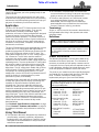
Introduction •The information contained within this manual was
current at the time of printing. Some parts may change
slightly to assure you of the best performance.
•To order a new Operator’s or Parts Manual contact
your authorized dealer. Manuals can also be
downloaded, free-of-charge from our website at
www.landpride.com or printed from the Land Pride
Service & Support Center by your dealer.
Terminology
“Right” or “Left” as used in this manual is determined by
facing forward while siting in the operator seat unless
otherwise stated.
Definitions
Owner Assistance
The Warranty Registration card should be filled out by
the dealer at the time of purchase. This information is
necessary to provide you with quality customer service.
If customer service or repair parts are required contact a
LandPridedealer.Adealerhastrainedpersonnel,repair
parts and equipment needed to service the mower.
The parts on your mower have been specially designed
and should only be replaced with genuine Land Pride
parts. Therefore, should your mower require
replacement parts go to your Land Pride Dealer.
NOTE: A special point of information that the
operator must be aware of before continuing.
IMPORTANT: A special point of information related
to its preceding topic. Land Pride’s intention is that
this information should be read and noted before
continuing.
For parts and service to your mower engine, contact
your nearest engine dealer or call Customer Service
Hotline provided below.
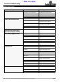
Owner’s Manual Part No.
Honda - 24 HP . . . . . . . . 31ZJ4621
Kaswaski - 25 HP. . . . . . 99920-2145-10
Kaswaski - 31 HP. . . . . . 99920-2232
Kohler - 27 & 30 HP . . . . 24 590 02
Service Manual Part No.
Honda - 24 HP . . . . . . . . 61ZJ410Z
Kaswaski - 25 HP. . . . . . 99924-2045-02
Kaswaski - 31 HP. . . . . . 99924-2089-01
Kohler - 27 & 30 HP . . . . TP-2450-C
Service Hotline Phone No.
Honda . . . . . . . . . . . . . . 1-770-497-6400
Kaswaski . . . . . . . . . . . . 1-800-433-5640
Kohler. . . . . . . . . . . . . . . 1-800-544-2444
Land Pride welcomes you to the growing family of new
product owners.
This mower has been designed with care and built by
skilledworkersusingqualitymaterials.Properassembly,
maintenance and safe operating practices will help you
get years of satisfactory use from the machine.
Application
The Accu-Z ZT60 and ZT72 Series Mowers from Land
Pride are commercial duty mowers. They are very
maneuverable, extremely comfortable, highly
productive, and come in cutting configurations designed
to meet the needs of even the most discriminating
owners and custom operators. This makes the Accu-Z
Series one of the premier choices of grass maintenance
machines for ranchers, farmers, large estate owners,
cemeteries, municipalities, campuses, and landscape
maintenance contractors.
TheAccu-ZSeriesMowerscomeequippedwithachoice
of either 60" or 72" cutting decks with high blade tip
speedsthatrangefrom18,768feetperminute on the 60"
deck to 18,574 feet per minute on the 72" deck. The
cutting decks adjust from 1/2" to 4 1/2" cutting height in
1/4" increments. The 60" deck meet the needs of
customers who need to mow in tighter areas around
obstacles or want to maintain a lower cutting height over
undulating terrain. The more productive 72" cutting deck
will meet the needs of customers with more level and
open areas to cut and just want to get the mowing job
done faster. The 60" cutting deck models offer a choice
of 24 hp Honda, 25 and 31 hp Kawasaki, and 27 and
30 hp Kohler air-cooled engines while the 72" deck
models offer a choice of 25 and 31 hp Kawasaki and 27
and 30 hp Kohler air cooled engines for proven
performance, power, and reliability.
Customers living in areas with hills or warmer and wetter
climates will typically want to employ the floating axle
capability for enhanced traction capability and a
smoother ride. Twin-lever hydrostatic steering will
enable 60" models to turn with-in their overall length.
Couple this outstanding maneuverability with a 10 mph
mowing speed and low center of gravity and you’ve got
mowing capability that’s fast, safe, comfortable, and
easytotransport. Topallof this offwith Land Pride’snew
electrically released automotive drum style braking
system.TheAccu-ZZT60andZT72Series Mowers from
Land Pride will meet the commercial duty needs
described above.
See “Section 6: Specifications & Capacities” on page
52 and “Section 7: Features and Benefits” on page 54
for additional information and performance enhancing
options.
Using This Manual
•This Operator’s Manual is designed to help familiarize
you with safety, assembly, operation, adjustments,
troubleshooting, and maintenance. Read this manual
and follow the recommendations to help ensure safe
and efficient operation.

9
Introduction
8/26/08 ZT60 & ZT72 Zero Turning Radius Mowers Riding Mowers Accu-Z® 357-103M
Land Pride Table of Contents
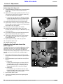
Serial Number Plate
For prompt service always use the serial number and
modelnumber whenordering parts fromyour LandPride
dealer.Besuretoincludeyourserialand modelnumbers
incorrespondencealso.Refer to Figure 1forthelocation
of your serial number plate.
Serial Number Plate Location
Figure 1
26689
Further Assistance
Your dealer wants you to be satisfied with your new
mower. If for any reason you do not understand any part
of this manual or are not satisfied with the service
received, the following actions are suggested:
1. Discuss the matter with your dealership service
manager making sure he is aware of any problems
you may have and that he has had the opportunity to
assist you.
2. If you are still not satisfied, seek out the owner or
general manager of the dealership, explain the
problem and request assistance.
3. For further assistance write to:
Land Pride Service Department
1525 East North Street
P.O. Box 5060
Salina, Ks. 67402-5060
E-mail address
lpser[email protected]

10
Section 1: Assembly & Set-up
ZT60 & ZT72 Zero Turning Radius Mowers Riding Mowers Accu-Z® 357-103M 8/26/08
Land Pride
Table of Contents
Section 1: Assembly & Set-up
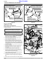
Uncrating Instructions
The shipping crate is assembled together at the corners
with nails and the Accu-Z is secured to the crate floor
with metal bands.
1. First pry the top panel free with a pry bar. Then
remove the side panels in the same way.
2. Cut metal bands securing front and rear wheels to
the crate floor. Discard bands.
3. Complete assembly instructions and engine
preparations below before driving mower off the
crate floor.
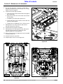
Control Lever & Seat Assembly (Standard Seat Shown)
Figure 1-1
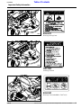
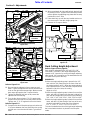
Control Lever Assembly
Refer to Figure 1-1:
Control levers (#1) are factory shipped rotated down and
secured with bolts in control levers.
1. Loosen bolt (#3A) on upper right control lever (#1).
2. Remove bolt (#3B) from lower right control lever (#8).
3. Rotatecontrol leverupuntil slotinuppercontrollever
aligns with hole in lower control lever.
4. Reinstall3/8"-16 1 1/2" GR5 hexhead bolt (#3B), flat
washer (#5) and 3/8" nylon lock nut (#4).
5. Repeat steps 1 to 4 for the left control lever.
6. Align control lever handles with each other and
tighten bolts (#3A & #3B) to the correct torque.
NOTE: For correct torque values, refer to
“Torque Values Chart” on page 58.
23940
Platform
Tabs
Seat Assembly
Refer to Figure 1-1:
The seat (#6) is shipped factory mounted to the hinged
seatplatform(#2)andattached to theshippingcratewith
four lag bolts.
1. Remove four lag bolts securing seat platform (#2) to
the shipping crate.
2. Spread control levers (#1) fully apart before
attaching the seat platform to the mower frame.
3. Pivot arm rest on the Deluxe Seat up.
4. Pivot back side of seat platform (#2) up about 45
degrees and Insert platform tabs through slots in the
mower platform and onto pins just below the slots.
5. Connect mower switch wires to the seat switch
located under the seat.
Refer to Figure 1-2:
6. Hinge seat platform down. The platform will latch
automatically. The following must be done if the seat
platform does not fit over the pilot pin (#2).
a. Loosen 3/8"-16 hex socket head cap screw (#1).
b. Adjust pilot pin (#2) to be centered in the seat
platform pin hole.
c. Tighten 3/8"-16 hex socket head cap screw (#1).
7. Being careful not to cut seat material, remove
protective packing around seat.
8. See "Seat Adjustment" on page 27 for positioning
this seat forward and rearward.
Seat latch Adjustment
Figure 1-2
NOTE: To make final control lever adjustments,
see "Upper Control Lever Adjustments" on page 27.
IMPORTANT: Be careful not to cut seat material
when removing protective packing around the seat.
Cutting seat material will void its warranty.
1
2
Pilot Pin (#2) (must be centered
in seat platform pin hole. 24828

11
Section 1: Assembly & Set-up
8/26/08 ZT60 & ZT72 Zero Turning Radius Mowers Riding Mowers Accu-Z® 357-103M
Land Pride Table of Contents
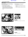
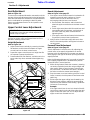
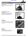
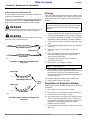
Discharge Chute Assembly
Refer to Figure 1-3:
Model ZT72 riding mower discharge chute is shipped
loose. ZT60 discharge chute is shipped attached.
1. Attach discharge chute (#1) to the deck by inserting
3/8"-16 x 1" GR5 round head square neck bolts (#2)
up through the deck bottom as shown.
2. Secure with 3/8" flanged locknuts (#3). Tighten nuts
to correct torque. See Torque Chart on page 58.
Discharge Chute Assembly
Figure 1-3
Hitch Plate Assembly
Refer to Figure 1-4:
A hitch plate (#1) is supplied with the mower and is
shipped turned around backwards and mounted to the
rear bumper.
1. Remove two 5/16"-18 x 5/8" GR5 hex flange
screws (#2) and hitch plate (#1) from under the
bumper.
2. Rotate and reinstall hitch plate (#1) as shown with
existing5/16"-18 x 5/8" GR5 hexhead flange screws.
3. Tighten 5/16" hex head flange screws (#2) to
17 ft. lbs. of torque.
Hitch Plate Assembly
Figure 1-4
24650
23990
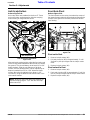
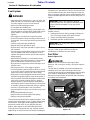
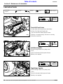
Electrical Cable Connection
Refer to Figure 1-5:
!WARNING
Incorrect battery cable connections can damage the mower’s
electrical system and cause battery cables to spark. Sparks
around a battery can result in a battery gas explosion and
personal injury.
• Always disconnect negative (black) battery cable before
disconnecting positive (red) cable.
• Always reconnect positive (red) battery cable to the
positive(+)postbeforereconnectingnegative(black)cable
to the negative (-) post.
!WARNING
Keep battery terminals from touching any metal mower parts
when removing or installing the battery. Do not allow metal
tools to short between the battery terminals and metal mower
parts. Shorts caused by battery terminals or metal tools
touching metal mower components can cause sparks. Sparks
can cause a battery gas explosion which will result in personal
injury.
Connect the black negative battery cable to the battery’s
negative post with 1/4"-20 x 3/4" GR5 hex head serrated
screw, flat washer, lock washer and nut before starting
the mower. Tighten hex nut to 8 ft. lbs. of torque.
Connecting the Negative Cable
Figure 1-5
IMPORTANT: Do not pull a trailer or implement
exceeding 300 pounds towing capacity and 50
pounds tongue weight. Loss of control may result.
Do not make turns that will cause a trailer or
implement being towed with the hitch to come in
contact with the mower or damage may result.
Negative Post
BlackNegative
Battery Cable
Positive Post
Located Under
Red Cover
Red Positive
Battery Cable
24576
IMPORTANT: The negative battery cable is
disconnected before leaving the factory and is to be
disconnected after initial dealer set-up to prevent
battery discharge while setting on the dealer lot.

12
Section 1: Assembly & Set-up
ZT60 & ZT72 Zero Turning Radius Mowers Riding Mowers Accu-Z® 357-103M 8/26/08
Land Pride
Table of Contents
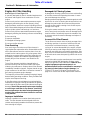
Engine Preparations
1. Check engine oil level at the dipstick. Add oil if oil is
below the full mark on the dipstick. Do not overfill.
Refertoengine manualforoil recommendation. Also
see"Engine Oil andOil Filter" instructions onpage 42.
2. Add gasoline with a fuel stabilizer to perform initial
starting operations. See "Fuel System" instructions
on page 41 before adding fuel.
Remove Mower From Crate Floor
1. Make a ramp in front and level with the crate floor to
be used for driving the mower off.
2. Checkunderthemowertomakesureitisnot banded
to the crate floor. Remove any bands that are still
present.
3. Following all precautions and operating information
provided in "Section 2: Operating Procedures"
before starting and driving the mower off.
4. Raise the deck fully up.
5. Start the engine and drive the mower forward off the
crate floor.
6. Make necessary adjustments to the mower as
outlined in "Section 3: Adjustments" beginning on
page 23.
NOTE:Mowersareshippedfromthefactorywiththe
fuel tanks empty.
IMPORTANT: Thoroughly read and understand
"Section 2: Operating Procedures", pages 13 to 21
before starting and moving the mower.

13
Section 2: Operating Procedures
8/26/08 ZT60 & ZT72 Zero Turning Radius Mowers Riding Mowers Accu-Z® 357-103M
Land Pride Table of Contents
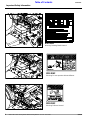
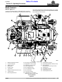
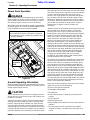
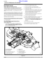
Mower Features
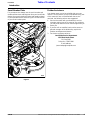
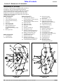
Refer to Figure 2-1:
Your Accu-Z riding mower is designed with innovative
and state-of-the -art features. Knowing the location and
how these features work will make handling your mower
morecomfortable. Below isalistofmajorfeatureswewill
be reviewing in this section.
Section 2: Operating Procedures
Accu-Z Features
Figure 2-1
12
11
14
13
10 26697
234
5
9
19
20
17
21
21
15
23
7
24
25
17
1
18
6
13
14
16
13
8
22
8
1. Blade Engagement Switch
2. Oil Pressure Light
3. Ignition Switch
4. Hour Meter
5. Throttle Lever
6. Choke Knob
7. Battery (Located under the seat)
8. Control Levers
9. Deck Height Indicator
10. Discharge Chute (Guard)
11. Right Deck Cover (Guard)
12. Left Deck Cover (Guard)
13. Anti-Scalp Wheels
14. Deck Adjusting Rod
15. Floor Platform (Guard)
16. Deck Lift Pedal
17. Fuel Caps & Tanks
18. Left/Right Fuel Tank Valve
(May be located on either side)
19. Seat Platform (Guard)
20. Rear Bumper/Muffler Shield (Guard)
21. Brake Release
(Located at rear under gas tanks)
22. Floating Axle
23. Front Axle Lock Pins
24. Seat Release Latch
25. Seat Adjustment Latch

14
Section 2: Operating Procedures
ZT60 & ZT72 Zero Turning Radius Mowers Riding Mowers Accu-Z® 357-103M 8/26/08
Land Pride
Table of Contents
Operating Check List
Hazard control and accident prevention are dependent
upon awareness, concern, prudence and proper training
involved in operation, transport, maintenance and
storage of the riding mower. Therefore, it is absolutely
essential that no one operates the mower without first
havingread, fully understoodand becometotally familiar
with the Operator’s Manual. Make sure the operator has
paid particular attention to:
•Important Safety Information, pgs. 1 to 7
•Section 1: Assembly & Set-up, pg. 10
•Section 2: Operating Procedures, pgs. 13 to 21
•Section 3: Adjustments, pgs. 23 to 31
•Section 5: Maintenance & Lubrication, pgs.34to 51
The following Operating Checklist should be performed
before operating your mower:
Instrumentation
Engine Oil Pressure Light
Refer to to Figure 2-2:
This light comes on when ignition switch is placed in
RUN position and stays lit until the engine is running with
a safe oil pressure. Shut engine off immediately if light
comes on during operation. Locate and correct the
problem.
Hour Meter
Refer to Figure 2-2:
Registers 1/10 hour increments up to 9,999.9 total hours.
The meter is connected to the ignition switch and records
accumulative time only while the engine is running. See
“Maintenance Schedule” on page 35.
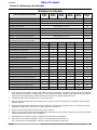
Operating Checklist
✔Check Reference
Read “Important Safety Information” Page 1
Read “Operating Procedures” Page 13
Lubricate mower as needed. Refer to Lubrication. Page 50
Check mower safety start interlock system daily
prior to operation. Page 16
Check mower initially and periodically for loose
bolts & pins, Torque Values Chart.Page 58
Make sure all guards and shields are in place. Page 13
Check blade for nicks and sharpness. Page 47
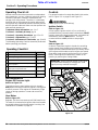
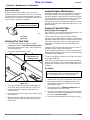
Controls
For general location of controls described in this section,
refer to Figure 2-1: on page 13 and Figure 2-2.
!WARNING
Do not operate mower while smoking!
Ignition Switch
Refer to Figure 2-2:
A three position ignition switch: off, run, and start is
provided.With keyinserted,rotateitclockwisetoSTART
position; release key when engine starts, and switch will
automatically return to RUN position. Turn key
counterclockwise to OFF position to stop engine.
Throttle
Refer to Figure 2-2:
A cable is linked from engine to throttle for controlling
engine speed. Move throttle lever forward to increase
enginerpm and rearwardto decreaserpm. Always travel
and cut grass with throttle set at full engine rpm speed.
Slow down travel speed by pulling back on the control
levers. Slow engine rpm speed only if mower is not
traveling or powering the cutting blades.
Control Panel
Figure 2-2
IMPORTANT: Always operate throttle at full engine
rpm speed while traveling or cutting grass. Slow
engine rpm may overheat the engine.
23686
Engine Oil
Pressure Light
Ignition Switch
Hour Meter
Throttle
Blade
Engagement
Switch
Choke

15
Section 2: Operating Procedures
8/26/08 ZT60 & ZT72 Zero Turning Radius Mowers Riding Mowers Accu-Z® 357-103M
Land Pride Table of Contents
Choke
Refer to Figure 2-2 on page 14:
A cable is linked from engine to choke knob to choke the
engine during starting. When choke control knob is
down, the choke is off (engine running position). When
controlknob ispulledup, thechoke is on(engine starting
position). Shut choke off soon after engine has started.
Blade Engagement Switch
Refer to Figure 2-2 on page 14:
The blade engagement switch engages the deck blades.
Pullswitch up toengage blades andpush switch downto
disengage blades.
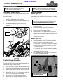
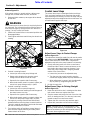
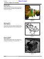
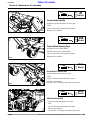
Left/Right Fuel Tank Valve
Refer to Figure 2-3:
Located in front and below the seat is the Left/Right Fuel
Tank Valve for controlling which fuel tank is in use. The
valve lever must be over one of the two arrows to supply
fuel to the engine. Arrows point to the fuel tank being
used. Switch valve from one tank to the other when tank
in use is about out of fuel. The mower does not have to
be turned off to make the switch. See “Fuel System” on
page 41 for more information.
Left/Right Fuel Tank Valve
Figure 2-3
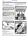
Control Levers
Refer to Figure 2-4 & Figure 2-5:
The control levers are used to steer, accelerate, brake
and change direction.
Always set both control levers in park position before
getting off the mower and always leave control levers in
park until seated and ready to start traveling.
IMPORTANT: DO NOT operate mower with the
choke pulled up or on. (engine starting position).
IMPORTANT: Never engage blades with engine
running at high rpm or when the deck is under load.
Clutch, belts or deck could be damaged.
26698
Left/Right Fuel Tank Valve
Center Position “O” as Shown is OFF
Pullcontrol levers together atthehandlestoreleasepark
brakes. Move control levers either forward or rearward
from neutral position to start moving.
Move the control levers to neutral to stop and to park to
set park brakes.
See “Driving the Mower” on page 17 for a detailed
description of operating the control levers.
.
Control Levers (Set in Park Position)
Figure 2-4
Control Levers (Set In Neutral Position)
Figure 2-5
IMPORTANT: Both control lever must be spread
fully apart before park brakes are applied.
23924
Both Control Lever Must Be Spread Fully
Apart Before Park Brakes Are Set.
23930
Control Levers Placed In
Neutral Operating Position
Neutral Slot

16
Section 2: Operating Procedures
ZT60 & ZT72 Zero Turning Radius Mowers Riding Mowers Accu-Z® 357-103M 8/26/08
Land Pride
Table of Contents
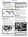
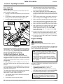
Deck Lift Pedal
Refer to Figure 2-6:
The deck lift pedal is used to raise and lower the deck
and to set deck cutting height.
1. Pushing on the deck lift pedal with your foot will raise
the deck.
2. Using the deck height indicator, place deck height
locking pin into the desired cutting height hole.
3. Lower deck gently against locking pin.
.
Deck Lift Pedal
Figure 2-6
When going over obstructions, push the deck liftpedal to
raise the deck. Go around the obstruction if the deck will
not raise high enough. Never mow over obstructions
you are not certain the deck will clear.
Safety Start Interlock System
The mower is equipped with a safety start interlock
system consisting of park switch, seat switch and blade
engagement switch. This system is an important mower
safetyfeaturedesigned to prevent runawayoraccidental
entanglement.
If blade engagement switch is ON or if a control arm is
out of park and the operator gets off the seat, the engine
will stop.
IfbladeengagementswitchisOFFandbothcontrolarms
are in park and the operator gets off the seat, the mower
engine will continue to run.
Thesafetystartinterlocksystemshouldbecheckeddaily
prior to operation and repaired immediately if it
malfunctions. Inspect system as follows:
1. The operator must be on the seat when testing the
seat safety switch.
2. Spread both control levers fully apart.
24518
Deck Lift
Pedal
DeckHeight
Indicator
DeckHeight
Locking Pin
3. Start mower engine per instructions outlined in
section on Engine Starting below. Allow engine to
warm up to operating temperature.
4. With blade engagement switch down (OFF), and
controlleversspreadfullyapart(setinparkposition),
slowly raise off the seat. The engine should continue
to run.
5. Pull the right control lever in and slowly raise off the
seat. The engine should stop within five seconds.
6. With control levers spread fully apart,restart engine.
7. Pull the left control lever in and slowly raise off the
seat. The engine should stop within five seconds.
8. With control levers spread fully apart,restart engine.
9. With control levers set in park position (fully apart)
and engine running at a slow idle, pull up on the
blade engagement switch to turn blades (ON).
Slowly raise off the seat. The engine should stop
within five seconds.
10. Replace seat safety switch if switch failed to operate
properly in any of the above steps and if no other
cause such as damaged wiring can be determined.
11. Contact your local Land Pride Dealer if the problem
cannot be located.
Engine Starting
!WARNING
Never leave the machine unattended with key in ignition
switch.
TheAccu-Z safetystartinterlocksystemisalsodesigned
to protect the operator and others from accidental injury
due to unintentional engine starting.
The following steps are correct procedures for starting
the engine. If difficulty is encountered, contact your local
Land Pride Dealer.
1. Perform daily pre-operation checks. (See
“Operating Check List” on page 14.)
2. Make sure both control levers are in park position,
and blade engagement switch is disengaged (OFF).
3. Set throttle at approximately 1/2 open position.
NOTE: The starting motor will not engage until both
control levers are spread full apart (Set in park
position) and blade engagement switch is in down
position (OFF).
The engine will stop if for any reason the operator
should become unseated when one or more control
levers are not in park position or if blade engagement
switch is (ON).
NOTE: Use choke when engine is cold or if warm
engine fails to start within 5 seconds of cranking.
Avoid flooding. Operate engine without choking as
soon as possible.

17
Section 2: Operating Procedures
8/26/08 ZT60 & ZT72 Zero Turning Radius Mowers Riding Mowers Accu-Z® 357-103M
Land Pride Table of Contents
4. Insert key in ignition switch and rotate clockwise to
engage starting motor. Release key when engine
starts.
5. Perform test to make sure safety start interlock
system is operating properly. Refer to “Safety Start
Interlock System” on Page 16.
6. As soon as engine begins to run, check to make
certain the oil warning light is off. If not, stop engine
immediately and check for the cause. Refer to
“Troubleshooting” on page 56.
7. Allow engine to idle a few minutes before advancing
throttle and/or engaging blades.
8. Before stopping the engine:
•Disengage blade engagement switch.
•Place both control levers in park position.
•Throttle back to low idle for one minute to allow
accumulated raw fuel to escape muffler during
engine slow down.
•Rotate ignition key counter-clockwise to (OFF)
position.
•Remove key from switch before leaving the seat.
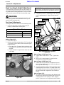
Driving the Mower
!DANGER
Never make sudden stops or sudden reversing of travel
direction, especially when going down a slope. The steering is
designed for sensitive response. Rapid movement of control
levers in either direction could result in a reaction that can
cause serious injury.
!DANGER
Never make sudden speed changes from reverse to forward.
Always push control levers forward gently to avoid sudden
change in speed. Any sudden forward speed change can cause
the front wheels to raise off the ground resulting in loss of
control, mower damage and/or personal injury.
To Start and Increase Speed
Refer to Figure 2-7 on page 18:
After starting the engine, engage control levers by
moving the handles towards each other. This moves the
levers from park position to neutral position and makes
them ready for steering while traveling.
Moving control levers an equal distance away from
neutral will increase travel speed.
•Start forward travel by gently pushing on the control
levers. The further forward the control levers are
pushed the faster the travel speed.
NOTE: Theengine starter shouldnot beoperatedfor
periods longer then 30 seconds at a time. An interval
of at least two minutes should be allowed between
such cranking periods to protect the starter from
overheating and burn-out.
•Startbacking upby gentlypulling on the control levers.
Thefurther back thecontrol levers arepulled the faster
the travel speed.
To Decrease Speed and Stop
!WARNING
In the event of a system shutdown while mowing, move control
levers to neutral and spread them fully apart to aid in slowing
and stopping the mower. See Figure 2-4 on Page 15. Also
turning the ignition switch to off will set the rear park brakes
without positioning of the control levers in park.
Refer to Figure 2-7 on page 18:
Moving control levers an equal distance towards neutral
will decrease travel speed.
•When moving forward, pull back gently on control
levers to decrease speed. The further back the control
levers are pulled the slower the travel speed until
neutral is reached.
•When backing up, push forward gently on control
levers to decrease speed. The further forward the
control levers are pushed the slower the travel speed
until neutral is reached.
•Move control levers to neutral to stop.
•Spreadbothcontrollevers fully aparttoapplyrearpark
brakes.
To Steer
Refer to Figure 2-7 on page 18:
•To Steer Straight While Traveling Forward:
Push control levers forward an equal distance.
•To Steer Straight While Backing Up:
Pull control levers rearward an equal distance.
•To Turn Left While Traveling Forward:
Moveright controllever fartherforward fromneutral
than the left control lever.
•To Turn Left While Backing Up:
Move right control lever farther back from neutral
than the left control lever.
•To Turn Right While Traveling Forward:
Move left control lever farther forward from neutral
than the right control lever.
•To Turn Right While Backing Up:
Move left control lever farther back from neutral
than the right control lever.
•To Make A Pivot Turn:
Move one control lever forward and the other
control lever back of neutral, this will allow the drive
wheels to counter-rotate.
IMPORTANT: Parks brakes will automatically apply
when ignition switch is turned off. This allows the
operator to set park brakes quickly without returning
control levers to park.

18
Section 2: Operating Procedures
ZT60 & ZT72 Zero Turning Radius Mowers Riding Mowers Accu-Z® 357-103M 8/26/08
Land Pride
Table of Contents
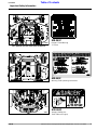
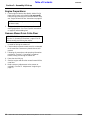
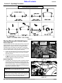
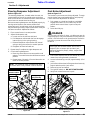
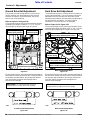
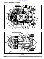
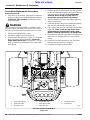
Moving Mower with Stalled Engine
Refer to Figure 2-8:
Located under the seat are two hydro-drives. One on the
right side and one on the left side. Each hydro-drive is
equipped with a bypass valve for moving the mower
manually when the engine is inoperable. The bypass
valve is located to the inside near the top and is identified
as a hex stud. Before moving mower manually:
1. Loosenhexjamnutswith17mmwrenchand turnboth
bypass valves with 8mm wrench counter clockwise
one-half of a turn.
2. Ifthe mowerhas electricalpower,turnignitionswitch
to (ON) andposition bothcontrol leversin neutral with
handles together to release park brakes.
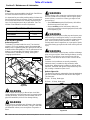
Refer to Figure 2-9:
3. If mower has lost electrical power, manually release
park brakes with release levers located at the rear
under the gas tanks. Raise levers and position them
into the notched slots. A pry bar leveraged over the
tires may be required to overcome the spring forces
required to set the park brakes.
.
IMPORTANT: Do not tow the machine. Move it by
hand or use a winch and load it on a trailer.
IMPORTANT: Following repairs and before
operating the mower, always make certain the two
bypass valves and two park brake release levers are
returned to their normal operating positions.
Bypass Valve (Left Side Shown)
Figure 2-8
Park Brake Release Lever (Right Side Shown)
Figure 2-9
23993
Bypass Valve
Hex Jam Nut
(17mm Wrench)
Hydro-Drive
Bypass Valve
(8mm Wrench)
23932
Figure 2-7
Front of Mower Faces This Direction
23923
Page is loading ...
Page is loading ...
Page is loading ...
Page is loading ...
Page is loading ...
Page is loading ...
Page is loading ...
Page is loading ...
Page is loading ...
Page is loading ...
Page is loading ...
Page is loading ...
Page is loading ...
Page is loading ...
Page is loading ...
Page is loading ...
Page is loading ...
Page is loading ...
Page is loading ...
Page is loading ...
Page is loading ...
Page is loading ...
Page is loading ...
Page is loading ...
Page is loading ...
Page is loading ...
Page is loading ...
Page is loading ...
Page is loading ...
Page is loading ...
Page is loading ...
Page is loading ...
Page is loading ...
Page is loading ...
Page is loading ...
Page is loading ...
Page is loading ...
Page is loading ...
Page is loading ...
Page is loading ...
Page is loading ...
Page is loading ...
-
 1
1
-
 2
2
-
 3
3
-
 4
4
-
 5
5
-
 6
6
-
 7
7
-
 8
8
-
 9
9
-
 10
10
-
 11
11
-
 12
12
-
 13
13
-
 14
14
-
 15
15
-
 16
16
-
 17
17
-
 18
18
-
 19
19
-
 20
20
-
 21
21
-
 22
22
-
 23
23
-
 24
24
-
 25
25
-
 26
26
-
 27
27
-
 28
28
-
 29
29
-
 30
30
-
 31
31
-
 32
32
-
 33
33
-
 34
34
-
 35
35
-
 36
36
-
 37
37
-
 38
38
-
 39
39
-
 40
40
-
 41
41
-
 42
42
-
 43
43
-
 44
44
-
 45
45
-
 46
46
-
 47
47
-
 48
48
-
 49
49
-
 50
50
-
 51
51
-
 52
52
-
 53
53
-
 54
54
-
 55
55
-
 56
56
-
 57
57
-
 58
58
-
 59
59
-
 60
60
-
 61
61
-
 62
62


Ask a question and I''ll find the answer in the document
Finding information in a document is now easier with AI
Related papers
-
 Land Pride 357-131A ZT72 User manual
-
Land Pride Z User manual
-
 Land Pride zst40 User manual
-
Zero ZSR Razor Series User manual
-
 Land Pride Z44 User manual
-
 Land Pride ZT60 Series User manual
-
 Land Pride Z52 Accu-Z Razor User manual
-
 Land Pride 357-187M User manual
-
Land Pride Lawn Mower & ZSR60 User manual
-
Land Pride ZT3 User manual


Other documents
-
Honda H3013H Owner's manual
-
Ridetech 11369570 Operating instructions
-
-
-
peak design M-MM-AA-BK-WEB-1 Operating instructions
-
peak design M-MM-AD-BK-WEB-1 Mobile Motorcycle Mount 1 Inch Ball Adapter Operating instructions
-
-
-
-
Toro 23in Dual Wheel Kit, Maxi Sneaker 370 Vibratory Plow Installation guide