Page is loading ...

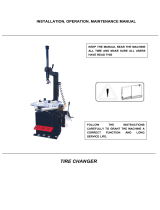
READ these instructions before placing unit in
service. KEEP these and other materials delivered
with the unit in a binder near the machine for ease
of reference by supervisors and operators.
Safety Instructions
Set-up Instructions
Operation Instructions
Maintenance Instructions
See
RIM Safety page 1
Operating
Instructions
on page 4.
1601 J. P. Hennessy Drive, LaVergne, TN USA 37086 615/641-7533 800/688/6359 www.coatsgarage.com Manual Part No.: 85613157 00
The COATS Company LLC. Manufacturer of COATS® Automotive Service Equipment and Tools. Revision: 3/23
* MAXX-80 Shown with Optional Cage
70/80/90
MAXX-Series
Rim Clamp® Tire Changers
For servicing single piece automotive
and most tubeless light truck tire/wheel
assemblies.
Any other type, including tube type agricultrual, require
special handling. Tires identied as truck tires need to
adhere to OSHA standard 1910.177.

ii • Important: Always read and follow operating instructions.
Read entire manual before assembling,
installing, operating, or servicing this
equipment.
NOTICE
Table of Contents
Tire Specifications Diagram ..................................... ii
Safety Instructions .................................................. iii
Owner’s Responsibility ............................................ iii
Operator Protective Equipment ...............................iii
Definitions of H azard Levels .................................... iii
Safety Notices and Decals ......................................iv
Remember R.I.M. .................................................... iv
Principle Operating Parts .................................... 2 - 3
Know Your Unit ................................................... 2 - 3
Operating Instructions ........................................ 4 - 9
Tire Bead Loosening and Demounting ............... 4 - 7
Tire Mounting ..................................................... 8 - 9
Inflation ............................................................ 10 - 13
Bead Sealing ........................................................... 11
Bead Seating ......................................................... 12
Inflation.................................................................. 13
Stages of Inflation on a Conventional Tire
and Rim ................................................................... 14
Mismatched Tires and Wheels ............................... 15
Performance, Custom, and Aluminum
Wheels .............................................................. 16 - 19
Performance Tires and Wheels • Demounting ...... 16
Aluminum and Custom Wheels ....................... 17 - 18
Performance Tires and Wheels • Mounting ........... 19
Leverless Bead Lifter Operation ............................ 20
Tire Demounting.................................................... 20
Tire Mounting ........................................................ 21
Custom and Special Wheels .................................. 22
Tube Type Tires ........................................................ 22
Maintenance Instructions ...................................... 23
Maintenance (Mount/Demount Tool) Cleaning ...... 23
Maintenance (Mount/Demount Tool)
Adjustment ............................................................ 24
Robotic Arm Maintenance ..................................... 24
Oil Injector Maintenance (if equipped) .................. 24
Pressure Limiter Maintenance .............................. 25
Setup Instructions .................................................. 26
Location ................................................................. 26
Air Source .............................................................. 26
Electrical Source .................................................... 26
Critical Safety Instructions ...................... Back Cover

Important: Always read and follow operating instructions. • iii
Tire Specification
T
I
R
E
N
A
M
E
P
2
1
5
/
6
5
R
1
5
9
5
H
M
+
S
M
A
N
U
F
A
C
T
U
R
E
R
T
R
E
A
D
W
E
A
R
2
2
0
T
R
A
C
T
I
O
N
A
T
E
M
P
E
R
A
T
U
R
E
A
Load index &
speed symbol
Rim diameter
code
Radial
Ratio of height to
width (aspect ratio)
Nominal width of
tire in millimeters
Passenger
car tire
U.S. DOT tire
identification number
Severe snow
conditions
Tire ply
composition
and materials
used
Max. load rating
Treadwear, traction
and temperature grades
Max.
permissible
inflation
pressure
R
A
D
I
A
L
T
U
B
E
L
E
S
S
D
O
T
M
A
L
9
A
B
C
0
3
6
T
R
E
A
D
4
P
L
I
E
S
2
X
X
X
X
X
C
O
R
D
S
I
D
E
W
A
L
L
2
P
L
I
E
S
2
X
X
X
X
X
C
O
R
D
M
A
X
.
L
O
A
D
1
3
0
0
L
B
S
M
A
X
.
P
R
E
S
S
.
3
5
P
S
I
Tire Specications Diagram

iv • Important: Always read and follow operating instructions.
Safety Instructions
Owner’s Responsibility
To maintain machine and user safety, the responsibility
of the owner is to read and follow these instructions:
• Follow all installation instructions.
• Make sure installation conforms to all applicable
Local, State, and Federal Codes, Rules, and Regula-
tions; such as State, Federal OSHA Regulations
and Electrical Codes.
• Carefully check the unit for correct initial function.
• Read and follow the safety instructions. Keep them
readily available for machine operators.
• Make certain all operators are properly trained,
know how to safely and correctly operate the unit,
and are properly supervised.
• Allow unit operation only with all parts in place and
operating safely.
• Carefully inspect the unit on a regular basis and
perform all maintenance as required.
• Service and maintain the unit only with authorized
or approved replacement parts.
• Keep all instructions permanently with the unit
and all decals/labels/notices on the unit clean and
visible.
• Do not override or bypass safety features.
Operator Protective Equipment
Personal protective equipment helps make tire ser-
vicing safer. However, equipment does not take the
place of safe operating practices. Always wear durable
work clothing during tire service activity. Loose fitting
clothing should be avoided. Tight fitting leather gloves
are recommended to protect operator’s hands when
handling worn tires and wheels. Sturdy leather work
shoes with steel toes and oil resistant soles should be
used by tire service personnel to help prevent injury
in typical shop activities. Eye protection is essential
during tire service activity. Safety glasses with side
shields, goggles, or face shields are acceptable. Back
belts provide support during lifting activities and are also
helpful in providing operator protection. Consideration
should also be given to the use of hearing protection if
tire service activity is performed in an enclosed area, or
if noise levels are high.
Definitions of Hazard Levels
Identify the hazard levels used in this manual with the
following definitions and signal words:
DANGER
Watch for this symbol:
It Means: Immediate hazards, which will result in
severe personal injury or death.
WARNING
Watch for this symbol:
It Means: Hazards or unsafe practices, which could
result in severe personal injury or death.
CAUTION
Watch for this symbol:
CAUTION
It Means: Hazards or unsafe practices, which may
result in minor personal injury or product or property
damage.
Watch for this symbol! It means BE ALERT! Your
safety, or the safety of others, is involved!

Important: Always read and follow operating instructions. • 1
Safety Notices and Decals
Failure to follow danger, warning, and caution
instructions may lead to serious personal
injury or death to operator or bystander or
damage to property. Do not operate this
machine until you read and understand all
the dangers, warnings and cautions in this
manual. For additional copies of either, or
further information, contact:
COATS Company, Inc.
1601 JP Hennessy Drive
LaVergne, TN 37086
(615) 641-7533 or (800) 688-6359
www.coatsgarage.com
For additional information contact:
USTIRE Manufacturers Association
1400 K Street N. W., Suite 900
Washington, DC 20005
(202) 682-4800
www.ustires.org
TGP Solutions, Inc.
The Tire Information Center
1101-6 South Rogers Circle
Boca Raton, FL 33487-2795
(561) 997-9229
www.tgp-solutions.com
Remember R.I.M.
Three Simple Steps To Help Keep Shops Safe
R.I.M. is a training program developed by Hennessy
Industries to help keep tire technicians safe. By follow-
ing the basic principles of R.I.M., technicians can avoid
situations that can cause catastrophic accidents like tire
explosions.
R.I.M. stands for read, inspect, and mount:
Read the tire size on a new tire before mounting to
make sure it is the proper size for the wheel.
Inspect the wheel for cracks, rust, and or other dam-
age that could cause an unsafe situation.
Mount the tire safely, making sure not to put any part
of your body over the tire during inflation.
The most serious of possible accidents is a tire explo-
sion. This is often caused by a tire/rim mismatch.
If a tire explodes on a tire changer, pressure causes it
to fly straight up at tremendous speed. If a technician
is standing over the tire, he can be seriously injured or
killed.
Hennessy’s R.I.M. program allows the technician to
avoid situations that can cause tire explosions and other
accidents. The full program, including training videos,
brochures, posters, and other materials, is available
from Coats distributors nationwide.
For more details, contact your Coats distributor or e-mail us.
READ INSPECT MOUNT

2 • Important: Always read and follow operating instructions.
Principal Operating Parts
Do It Now!
Now is a good time to contact product service
(800-688-6359) to start warranty, otherwise
warranty starts at time of shipment.
Know Your Unit
Compare this illustration with the unit before
placing it into service. Maximum performance
and safety will be obtained only when all per-
sons using the unit are fully trained in its parts
and operation. Each user should learn the func-
tion and location, of all controls.
Prevent accidents and injuries by ensuring
the unit is properly installed, operated and
maintained.
11
12
13
14
15
16
17
18
19 20
21
22
23
24
9
Dual Nozzles
1
2
3
4
5
6
7
8
10

Important: Always read and follow operating instructions. • 3
CAUTION
Replace any damaged or missing safety
decals. They are available from COATS, (800)
688-6359.
1 Pressure Safety Valve — The high pressure safety
valve is set to exhaust at line pressures above 200 PSI.
2 Release Valve — Allows the manual release of air
pressure from tire when clip-on chuck is attached to
tire valve.
3 Air Inflation Gauge — Registers tire pressure when
clip-on chuck is attached to tire valve stem and inflation
pedal is released.
4 Swing Arm Adjustment Knob — Adjusts swing
arm/vertical slide assembly for proper horizontal posi-
tioning of mount/demount tool.
5 Lube Bucket Bracket — Dispenser for rubber lubri-
cant.(Lube not Shown)
6 Inflation Pedal — Three-position pedal that allows
inflation of tires through air hose and clip-on chuck.
7 Robo-Roller™ — Provides extra leverage for runflat
and low profile tires.
8 DuckHead® (Combination Mount/Demount Tool)
— Mounts and demounts tire from wheel.
9 Swing Arm Lock Handle — Slides to lock and
unlock swing arm position. Available on units equipped
with a factory installed Leverless Bead Lifter.
10 Robo-Arm Control Valve — Controls vertical
movement of robo arm cylinder.
11 Robo-Arm™ — Provides extra leverage for runflat
and low profile tires.
12 Clamps — Holds wheel to table top for tire chang-
ing. Position outward to allow outside clamping of
wheels.
13 Bead Sealing Nozzles — Expands tire sidewall
to bead seat area of rim to seal tire to rim and allow
inflation.
14 Table Top — Rotating chuck for tire changing.
15 Clamp Control Pedal — Three-position pedal that
opens, holds or closes rim clamps.
16 Bead Loosener Control Pedal — Controls opera-
tion of bead loosener shoe.
17 Table Top Pedal — Four-position pedal that controls
rotation of table top (forward-fast, forward-slow, off,
reverse).
18 Bead Lifting Tool — Used to lift and position tire
bead correctly on DuckHead mount/demount tool.
19 Tire Bumper Guards — Provides protective sur-
face when bead loosening tires.
20 Bead Loosener Shoe — Pivoting shoe for loosen-
ing tire beads.
21 Bead Loosener Handle — Controls operation of
bead loosener shoe. Pull handle up or down on some
models.
22 Important Safety Decal — Important safety infor-
mation for the operator. DO NOT obstruct with tire
stickers or other materials.
23 Tower — Support for horizontal and vertical slides,
also air storage tank.
24 Vertical Slide Locking Handle — Locks and
unlocks vertical slide and sets correct vertical position
to maintain head/wheel clearance.

4 • Important: Always read and follow operating instructions.
Operating Instructions
This unit must be properly operated and properly
maintained to help avoid accidents that could injure
the operator or bystanders, or damage the unit. This
section of the Operating Instructions manual review
basic operations and use of controls. These instructions
should be reviewed with all employees before they are
allowed to work with the machine. Keep these instruc-
tions near the machine for easy reference.
Tire Bead Loosening and Demounting
CAUTION
This machine may operate differently from
machines you have previously operated.
Practice with a regular steel wheel and tire
combination to familiarize yourself with the
machine’s operation and function.
NOTE: Remember to remove all weights from
both sides of the wheel. Weights left on backside
of wheel may cause the wheel to be clamped
unleveled. This may result in the combination mount/
demount tool contacting the rim causing scratches.
On alloy wheels, always rotate the wheel one turn
after setting the Duckhead mount/demount tool to
insure proper wheel clamping.
NOTE: Always review with the owner any nicks and
scratches on expensive wheel and tire combina-
tions prior to servicing.
NOTE: Review the performance wheel section of
this manual prior to servicing performance tire/
wheel combinations.
CAUTION
Loosening the beads on a partially or fully
inflated tire is unsafe and causes excess
movement and friction against the bumper
pads and excessive wear on pivots. Deflate
the tire completely to prolong the life of
your machine.
1. Deflate the tire completely by removing the valve
core from the valve stem (figure 1). Be cautious and
do not smoke as a flammable gas could have been
introduced into the tire at some time.
Figure 1 - Remove Valve Core to Deflate Tire
CAUTION
Tires are always installed and removed from
the rim’s narrow side.
NOTE: Always loosen the bead on the narrow side
of the wheel’s drop center first (tire removed in
figure 2 for clarity).
Figure 2 - Determine Narrow Side of Wheel
NOTE: The clamps on the table top may extend
beyond the table top itself. To avoid damaging the
clamps, move them to their full inward position
before positioning a tire for bead loosening.
NOTE: Use extra care in positioning the bead
loosener shoe on larger wheels/tires, and on alloy
wheels. Make sure the shoe rests next to but not
on the rim, and not on the tire sidewall.
2. Actuate valve (or pull) to position the bead loosener
shoe away from the machine and roll wheel into posi-
tion. The valve stem should be in the 2 o’clock position
to accommodate a possible asymmetric safety hump
type rim. Position the bead loosener shoe against
the tire next to, but not on, the rim. Actuate the bead
loosener handle/button to position the shoe or press the
bead loosener pedal to position the shoe and loosen
the bead. It may be necessary to loosen the bead in
multiple locations around the tire (figure 3).
Narrow Side
Drop Center
Long Side

Important: Always read and follow operating instructions. • 5
Figure 3 - Position Tire and Bead Loosener Shoe with Valve
Stem in 2 o’clock Position.
3. Turn the wheel around and repeat loosening pro-
cedure on the other side of the wheel (figure 4). This
should be the long side of the drop center (figure 2).
Figure 4 - Position Tire and Bead Loosener Shoe With Wheel
Turned Around and Valve Stem in 2 o’clock Position.
NOTE: It will be easier to outside clamp the wheel
to the table top if the long side of the rim is loos-
ened last.
4. Apply tire manufacturer’s approved rubber lubricant
liberally to entire circumference of both tire beads after
loosening (figure 5).
Figure 5 - Apply Rubber Lubricant to Tire Beads
5. Determine the mounting side of the wheel. The
mounting side is the narrow side of the drop center. See
figure 2 for more information on the drop center.
NOTE: The wheel clamps can be positioned in one of
two different ranges: Use the inner holes for 6-22-inch
diameter wheels and the outer holes for 8-24-inch
wheels.
6. Place tire/wheel assembly on table top with mount-
ing side up (figure 6).
Figure 6 - Place Tire/Wheel Assembly on Table top
CAUTION
Clamp control pedal must be in the full up
or full down position (detent position) to
maintain clamping force on wheel.
7. Use Robo Arm to apply pressure to aid in clamping
rim (figure 7). Use the clamp control pedal to move the
clamps inward (push pedal down) or outward (lift pedal
up). Engage the detent position (pedal in full up or full
down position) to maintain clamped or unclamped
pedal position.
Clamp steel wheels from the inside (clamps push out-
ward against wheel). Clamp mag and custom wheels
from the outside (clamps push inward against the
outside rim edge). Refer to the Performance Tires and
Wheels section.
Figure 7 - Robo Arm Aids Clamping
Valve Stem at
2 o’clock Position
Narrow Side
Mounting Side Up
Protective Pad
or Cloth
Valve Stem at
2 o’clock Position

6 • Important: Always read and follow operating instructions.
8. Move the swing arm into position. Pull the locking
handle forward to release the slide. Push down on the
top of the vertical slide
to move the demount
tool into contact with
the rim edge. Push the
locking handle back and
lock the slide into place.
As the slide is locked,
the mount / demount
tool will move upward
approximately 1/8-inch
from rim edge (figure 8).
Figure 8 - Position Mount/Demount Tool
9. The mount/demount tool should be in contact with
the rim edge. Turn the swing arm adjusting knob to
move the mount/demount tool away from the rim 1/8
to 1/4 inch (figure 9).
Figure 9 - Adjust Swing Arm to Position Tool
10. Check metal tool positioning. Mount/demount
metal tool should be positioned with 1/8 to 3/16 inch
clearance between the top of the rim edge and the
bottom of the tool, and 1/8 to 1/4 inch clearance
between the rim edge and the tool roller. This clearance
will be maintained as long as the locking handle and
adjustment knob are not changed. The operator may
swing the arm out of the way and back into place again
without needing to reposition the tool (when changing
a like set of wheels) (figure 10).
Figure 10 - Proper (Metal) Mount/Demount Tool Position
11. Check plastic tool positioning. Mount/demount
plastic tool should be positioned with 1/16 to 1/8 inch
clearance between the top of the rim edge and the
bottom of the tool, and 1/16 to 1/8 inch clearance
between the rim edge and
the inside surface of the
tool. This clearance will
be maintained as long as
the locking handle and
adjustment knob are not
changed. The operator
may swing the arm out
of the way and back into
place again without need-
ing to reposition the tool
(when changing a like set
of wheels) (figure 11).
Figure 11 - Proper (Plastic) Mount/Demount Tool Position
NOTE: The tool clearance may change with machine
use and should be inspected often. Failure to main-
tain the proper clearance may result in damage to
the wheel rim and/or tire.
NOTE: Normal table top rotation for demounting
is clockwise. Depress the table top pedal to rotate
this direction. To rotate the table top counterclock-
wise, lift the pedal up with your toe.
NOTE: Table top rotation can be stopped at any
time by removing your foot from the rotation pedal.
CAUTION
At times during the mounting and demount-
ing procedure, the bead lifting tool may
encounter resistance and can be thrown.
Keep one hand firmly on the tool to avoid
possible tool disconnect. Use the reversing
feature to back out of jam-ups. A thrown
tool can cause injury.
12. Insert the smooth curved end of the bead lifting
tool over the forward end of the demount tool and
below the top bead of the tire (figures 12 & 13). Lift
the bead up and over the knob on the demount tool
(figure 12 & 13). Also, note the valve stem position to
the demount tool. Use the Robo-Arm® to push down
on the tire opposite the demount tool to allow the bead
to utilize the drop center area of the rim, this position
reduces stresses in the bead and allows an easier bead
lift.
3/16" to 1/8"
1/8" to 1/4"
1/16" to 1/8"
1/16" to 1/8"

Important: Always read and follow operating instructions. • 7
Figure 12 - Insert Bead Lifting Tool
13. Push the bead lifting tool down towards the
wheel to lift the tire bead up and over the knob portion
of the demount tool. Hold the tool and bead in this
position (figure 13).
Figure 13 - Lift Bead Over Demount Tool
14. Depress the table top pedal to rotate the wheel.
The Duckhead mount/demount tool will guide the tire
bead up and over the edge of the wheel. Continue rota-
tion until the upper bead is demounted.
NOTE: Push down on the tire across from the
demount tool during table top rotation to utilize
the drop center area of the wheel. This reduces
the tensional force on the top or first bead during
demount (figure 12).
Figure 14 - Demounting Lower Bead
15. Lift and hold the tire at an angle so that the lower
bead is resting in the drop center directly across from
the demount tool, and is loose below the demount tool
(figure 14). Insert the smooth curved end of the bead
lifting tool down over the forward end of the mount/
demount tool and below the lower bead. Lift the bead
up and over the knob on the demount tool (figure 15).
Figure 15 - Guide Lower Bead Over Knob On Demount Tool
16. Depress the table top pedal to rotate the wheel.
The demount tool will guide the bead up and over the
edge of the wheel. Continue rotation until lower bead
is demounted.
Valve Stem
Push down

8 • Important: Always read and follow operating instructions.
Tire Mounting
This information must be read and followed carefully
to prevent accidents and injuries during mounting.
Mounting a mismatched tire and wheel will
cause an explosion before it bead seats
during inflation. Attempts to force a bead
seat, by increasing air pressure, on mis-
matched tires and wheels will cause the
tire to violently explode, causing serious
personal injury or death to operator and/or
bystanders if standing over tire and wheel.
Check tire and wheel carefully before mount-
ing. Make sure the tire bead diameter and
wheel diameter match exactly. Consult the
tire manufacturer’s recommendations, Tire
Guide and/or Rubber Manufacturer's Asso-
ciation for approved rim widths for tire sizes.
Never mount a damaged tire. Never mount a
tire on a rusty or damaged wheel. Used tires
may have bead and/or tread damage. Used
rims may have flange damage where the
tire/rim was run down the road on a flat tire.
Run-flat tires are not meant to be reused!
Damaged tires and/or wheels may explode.
CAUTION
When in doubt do not mount. Never mount
a tire and wheel handed to you by anyone
without checking both tire and wheel for
damage and to be certain the sizes match.
Used tires may have road hazard damage or
mount/demount damage, inspect carefully.
Do not let untrained persons operate tire
changer and keep bystanders out of service
area.
CAUTION
Forcing the tire onto the rim can cause bead
damage. If you damage the tire bead during
mounting, STOP!, remove tire and mark it
as damaged. Do not mount a damaged tire.
1. Before any mounting, inspect tire for damage and
verify size match between tire and wheel (figure 16).
Figure 16 - Verify Size Match Between Tire and Wheel
2. Inspect wheel closely for damage. Clean the wheel
and remove any light corrosion or rubber residue (figure
17). Do not attempt to service a heavily corroded wheel,
damaged wheel, or bent wheel.
Figure 17 - Inspect and Clean the Wheel
3. Inspect valve stem and replace if necessary. Next
lubricate tire beads liberally with tire manufacturer’s
approved rubber lubricant (figure 18).
Figure 18 - Lubricate Tire Beads Liberally

Important: Always read and follow operating instructions. • 9
4. Place tire over wheel and move swing arm into
position making sure the valve stem is at the 9 o’clock
position in front of bead lock. Position tire so that lower
bead is above the rear extension of the mount/demount
tool and below the front knob (figure 19).
Figure 19 - Position Tire Against Mount/Demount Tool
5. Depress table top pedal and rotate wheel to mount
lower bead. Use drop center of wheel by pushing down
on tire just ahead of the mounting tool, and follow as
tire rotates (figure 20). Rotate table top until lower bead
is mounted.
Figure 20 - Mounting Lower Bead
6. For top bead installation, rotate table top until
the valve stem on wheel is 180 degrees ahead of the
mount tool (3 o’clock position). Pull ring on locking pin
and attach Duckhead roller to the Duckhead mount tool;
using Robo Arm to assist (figure 21).If equipped
Figure 21 - Position Valve Stem 180º Ahead of Mount Tool
Release locking pin making sure the Duckhead roller
mount is fully engaged on the arm bracket; with no gap
(figure 22). If equipped
Figure 22 - Duckhead Roller Properly Mounted On Bracket
7. Use Robo Arm™ to push down on tire 90 degrees
clockwise from mount/demount tool to allow bead to
utilize drop center area of rim.
Fig 23 - Use Robo Arm To Hold Tire In Rim Drop Center
8. Depress table top pedal and rotate tire until bead
is mounted. Be careful to ensure bead stays in the rim
drop center in the area ahead of Duckhead mount tool.
Figure 24 - Mounting Top Bead
NOTE: If table top rotation stalls, reverse the table
top momentarily until the tire bead is again loose
on the wheel. Add more lubricant to assure the tire
bead slides into the drop center. Reposition tire on
Duckhead mount/demount tool and make sure the
tire bead is correctly positioned in drop center of
the wheel; then attempt mounting again.
180º
Valve Stem

10 • Important: Always read and follow operating instructions.
Ination
Tire inflation is performed in three steps: BEAD SEAL,
BEAD SEAT, and INFLATION. These steps are explained
in detail on page 14. Read the explanation of each step
and understand them thoroughly before proceeding.
Tire failure under pressure is hazardous.
This tire changer Will Not Restrain Explod-
ing Tires, rims or other related equipment.
Inspect tire and wheel carefully for match,
wear, damage, or defects before mounting.
Always use approved tire bead lubricant
during mounting and inflation.
CAUTION
The clip-on chuck allows the operator to
keep hands and entire body back from inflat-
ing tire. The chuck must be an open/free
flow style with all parts in proper working
order.
CAUTION
Check for proper inflation gauge operation.
Accurate pressure readings are important
to safe tire inflation. Refer to the Operat-
ing Maintenance section of this manual for
instructions.
CAUTION
If the rim has been clamped from the outside
for tire mounting, release the clamps, lift the
tire, and move the clamps to the center of
the table top.
CAUTION
If the wheel/tire has a diameter larger than
14-inches and is difficult to bead seal, the
clamps should be moved to the center of the
table top for the bead seal operation.
The inflation pedal, located at the rear of the left side
of the machine, controls the flow of air through the
inflation hose, and has three positions.
Note: The clip-on chuck on the end of the hose is a
safety item that must always be an open/free flow style
with all parts in proper working order.
Position 1 - Tire Pressure – With the inflation hose
attached to the tire valve and the pedal in this position,
the air gauge will register the air pressure in the tire.
Whenever your foot is removed from the pedal, it will
return to this position.
Position 2 - Tire Inflation – This is the first activated
position. With the inflation hose attached (using the
clip-on chuck) to the tire valve and the pedal in this
position, line pressure is allowed to flow through the
valve system and into the tire for inflation. Correct tire
pressure is not indicated on the gauge in this position.
Position 3 - Bead Sealing – This is the second and
last activated position. With the inflation hose attached
to the tire valve and the pedal in this position, line pres-
sure is allowed to flow through the valve and to the
air-flate bead seal jets for bead sealing.
Note: If the rim has been clamped from the outside
or inside for holding during the bead sealing process.
once the bead is seal achieved release the clamps and
lift the tire, and move the clamps to the center of the
table top.
Note the Inflation Pedal Positions (See Diagram)
Tire Pressure Tire Inflation Bead Sealing
Inflation Pedal Positions

Important: Always read and follow operating instructions. • 11
CAUTION
Use of bead sealing jets without a tire in
place can cause dirt and debris to be blown
into the air with enough force to injure
operator and/or bystander. Do not use the
bead sealing control position to inflate a tire.
NOTE: This unit is equipped with a pressure limiter
to assist the operator with proper tire inflation.
When the inflation pedal is held in position 2,
the pressure limiter cycles the system between
position 2 (inflation) and position 1 (at rest, no
airflow to tire). This cycling helps to prevent over
inflation of the tire. Tires can still be over inflated
and explode, when using this pressure limiter, if all
of the instructions in this manual are not followed
completely. The pressure limiter will keep most car
and light truck tires from inflating beyond 60 PSI
(smaller tires may reach higher pressures). It is the
operator's responsibility to follow all instructions
and to control inflation pressure as specified in
these instructions. Check the function of the pres-
sure limiter regularly and maintain it according to
the instructions provided in this manual for safe and
proper operation. Do not tamper with or attempt to
adjust the pressure limiter. Tires requiring inflation
beyond 60 PSI should be inflated in a safety cage.
Adjustable Bead Sealer
NOTE: To adjust the bead sealing nozzles to the
optimal angle. Loosen the handles on both sides
and lift the nozzles up for larger diameter wheels
or lower them for smaller diameter wheels. Then
retighten the handles before starting the bead seal-
ing process.
Bead Sealing
1. Remove the valve core from the valve stem to
allow more air flow into the tire to assist with bead seal.
2. Position valve stem in front of operator and con-
nect the inflation hose with the clip-on chuck. Hold
tire up against upper edge of the wheel whith wheel
clamped. Be sure tire’s top bead does not cover the
bottom of the valve stem (figure 25).
Figure 25 - Lift Tire Upwards for Bead Sealing
3. Depress inflation pedal to position 2 and hold
about one second to begin air flow through tire valve,
then depress pedal to position 3 and hold briefly — less
than one full second. The blast of air from the jet(s) will
expand tire and seal the beads.
4. Release the inflation pedal and allow it to return to
position 1. Verify that both beads are completely sealed
to the wheel. Repeat these steps if beads have not
sealed. It may be necessary to wait a few seconds for
the air storage tank pressure to recover before attempt-
ing again.
5. After bead seal is achieved, un clamp the wheel.
Then remove the clip-on chuck and reinstall the valve
core. Reattach the clip-on chuck after core is installed.
Handle

12 • Important: Always read and follow operating instructions.
Bead Seating
NEVER exceed 40 PSI to seat beads while
using this tire changer. If more than 40 PSI
is permitted by tire manufacturer, ALWAYS
use safety cage and clip-on chuck. NEVER
exceed recommended pressure after seating
beads. ALWAYS keep hands and entire body
back from inflating tire.
An exploding tire, wheel, or bead sealing
equipment may propel upward and outward
with sufficient force to cause serious injury
or death to operator or bystander.
Check tire pressure frequently. If operator is
unable to obtain Bead Seat, something is
wrong. Deflate tire completely, inspect tire
and wheel, correct any problems found, relu-
bricate both tire beads, and reattempt Bead
Seal and Seat procedures. Follow all safety
instructions in this manual and on machine.
1. Once tire pressure is indicated on the air gauge
(inflation pedal in position 1; foot removed from pedal),
continue to inject air into the tire (inflation pedal posi-
tion 2) in short intervals. Check the pressure frequently.
Stand back during bead seat. Keep hands, arms, and
entire body away from tire during this procedure (figure
26).
Tire beads should move outward and “pop” into their
bead seat position as pressure inside the tire increases.
If this does not happen, a problem exists. Investigate
carefully.
Important: Do not continue to add air pressure to
force bead seat.
Figure 26 - Stand Back during Bead Seat

Important: Always read and follow operating instructions. • 13
Inflation
NEVER exceed tire manufacturer's recom-
mended air pressure. Tires can explode,
especially if inflated beyond these limits.
Use clip-on air chuck, keep hands, arms
and entire body back from inflating tire.
Avoid distraction during inflation. Check
tire pressure frequently to avoid over infla-
tion. Excessive pressure can cause tires to
explode, causing serious injury or death to
operator or bystander.
If you change tires defined as truck tires,
they must be inflated per OSHA instructions.
1. Make sure both beads are seated. When both
beads are seated, the tire is ready for inflation.
2. Replace the valve core if it was removed.
3. Depress the inflation pedal to position 2 to inflate
the tire. The pressure limiter will cycle the air flow as
described earlier. On most tires, the pressure limiter
will cease air flow at approximately 60 PSI. On smaller
volume tires the pressure may be higher.
4. Release air pressure from tire by pressing the
manual release valve button (inflation hose must be
attached to the valve stem, Figure 27). Never add or
adjust tire pressure using an air hose without a clip-on
air chuck and in-line valve. Do not use a hand-held style
chuck (figure 28).
5. Important: When inflating tires that require more
than 60 PSI, always use a safety cage and air hose with
a clip-on air chuck and in-line valve. The air hose must
have enough length between the chuck and the opera-
tion/in-line valve to allow the operator to stand outside
the trajectory.
Figure 27 - Location of Manual Release Valve
Figure 28 - Do Not Use a Hand-held Style Air Chuck
Manual Release Valve
Explosion Hazard
Never exceed 40 PSI while
seating beads. If you use
more than 40 PSI always
use safety cage.
Remember R.I.M.
(see page iv and back cover)
Explosion Hazard
Never inate tire
above
manufacturer’s
recommended
pressure after
bead is seated.

14 • Important: Always read and follow operating instructions.
Stages of Ination on a
Conventional Tire and Rim
Review these descriptions and diagrams carefully. Refer to them as
necessary during bead sealing, bead seating, and inflation to verify that
you are proceeding properly and safely.
Bead Sealing
Bead sealing is the process of capturing air pressure between the
tire and the rim. The tire will usually contain about 1/2 to 2 PSI at initial
bead seal.
Bead Seating
Bead seating usually occurs on the long tapered side of the wheel
first and the shorter side last. Bead seating will usually require at least
7 PSI in the tire. 40 PSI is the maximum safe pressure at this stage
regardless of tire operating pressure. For tires requiring more than 40
PSI to bead seat use safety cage.
Most European import cars and many aftermarket alloy wheels are
very tight and can be difficult to bead seat. Also note that asymmetrical
hump and run-flat tires are extremely difficult to bead seat. Follow tire
manufacturer’s recommended procedure for bead seating.
Inflation
After the beads are seated, the tire is ready to be inflated. Do not
inflate the tire above the manufacturer’s recommended pressure as
stamped on the tire sidewall. The typical inflation pressure for auto-
mobile tires is between 24 and 45 PSI. Light truck inflation pressure
typically covers a wider range.

Important: Always read and follow operating instructions. • 15
Mismatched Tires and Wheels
Never mount and inflate mis-matched tires and
wheels.
Mismatched tire and wheel combinations will explode,
if you attempt to force a bead seat, causing personal
injury or death to operator and/or bystanders.

16 • Important: Always read and follow operating instructions.
Performance, Custom and
Aluminum Wheels
CAUTION
Only tire technicians with experience and
training on custom wheels should attempt
to service expensive custom alloy or alu-
minum wheels and high-performance low-
profile tires.
Pre-Operation Notes:
• Ensure all weights have been removed.
• Clamp wheel from the outside.
• Use ample lubricant for mount and demounting.
• Always review wheel nicks and/or scratches with
the owner before servicing.
Performance Tires and Wheels • Demounting
Follow these instructions for performance type tires
and wheels, including run-flat tires and their associated
wheels, and asymmetrical hump wheels.
1. Remove valve core and completely deflate tire.
2. Pull the bead loosener shoe away from the machine
and roll the tire into position against the bumper pads.
Position the tire with the valve stem in the 2 o’clock
position (in direct line with the bead loosener shoe).
Always loosen the bead on the narrow/mounting side
of the wheel first (figures 2 and 29).
Figure 29 - Position Tire for Bead Loosening
NOTE: Wheels with an asymmetrical hump have a
larger “ledge” type hump around the wheel except
at the valve hole making them more difficult to
mount and demount (figure 30). Always loosen the
beads near the valve stem on both sides of rim.
Figure 30 - Asymmetrical Hump Wheel
NOTE: Some wheels/tires have a low pressure
sensor/transmitter strapped to the wheel (figure
31). This is especially true on run-flat tire/wheel
systems. The sensor is positioned directly opposite
from the valve stem. Other low pressure warning
systems have the sensor as part of the valve. To
avoid damaging the sensor, always loosen the top
bead with the valve stem at the 2 o’clock position
first, then loosen the bottom bead with the valve
stem at the 2 o’clock position, and then continue to
loosen the remaining circumference of the beads as
necessary. Avoid loosening at 180 deg. (opposite)
the valve.
Figure 31 - Wheel with Low Pressure Sensor/Transmitter
3. Loosen bottom bead, starting with valve stem at
2 o‘clock position next to the loosener shoe (figure 32).
Figure 32 - Loosen Bottom Bead
Valve Stem
Smooth
Hump
At Valve
Hole
Ledge
Hump -
Rest of
Wheel
Valve Stem
Sensor
/