Page is loading ...

ProX™ 500
3D Production Printer
User Guide
Original Instructions

3D Systems, Inc.
2
CONTENTS
1
INTRODUCTION .......................................................................................6
About This Guide ....................................................................................6
What’s Inside? ......................................................................................6
Other Documents ....................................................................................6
Material Guides .....................................................................................6
ProX 500 Facility Guide ...............................................................................6
2
INTRODUCTION TO THE PROX™ 500 .....................................................................7
Auxiliary SLS Equipment .............................................................................11
Nitrogen Generator .................................................................................11
Bead Blaster (Optional) ..............................................................................11
ProX 500 System Components ........................................................................12
ProX 500 User Interface .............................................................................12
Part Transfer Cart Assembly ..........................................................................15
ProX 500 Stack Lights ...............................................................................15
MQC System Components ............................................................................16
MQC System User Interface ..........................................................................16
Sifter Switch .......................................................................................17
Fresh Material Input. . . . . . . . . . . . . . . . . . . . . . . . . . . . . . . . . . . . . . . . . . . . . . . . . . . . . . . . . . . . . . . . . . . . . . . . . . . . . . . . . 17
SAFETY GUIDELINES AND INSTRUCTIONS ................................................................18
General Guidelines ..................................................................................18
Training and Instructions .............................................................................18
Machine Handling ...................................................................................18
Material Handling ...................................................................................18
Laser. . . . . . . . . . . . . . . . . . . . . . . . . . . . . . . . . . . . . . . . . . . . . . . . . . . . . . . . . . . . . . . . . . . . . . . . . . . . . . . . . . . . . . . . . . . . . . 18
Alarms and Warnings ................................................................................18
Safety Symbols and Definitions .......................................................................19
First Aid Section – What to do .........................................................................20
Burns ............................................................................................20
Reporting Laser Radiation Exposure. . . . . . . . . . . . . . . . . . . . . . . . . . . . . . . . . . . . . . . . . . . . . . . . . . . . . . . . . . . . . . . . . . . . 20
Electrocution ......................................................................................20
SLS Equipment Safety Features .......................................................................21
Safety Interlocks ...................................................................................21
SLS System Response if an Interlock Fails. . . . . . . . . . . . . . . . . . . . . . . . . . . . . . . . . . . . . . . . . . . . . . . . . . . . . . . . . . . . . . . 21
Limited Access and Barrier Shielding ...................................................................21
Other Active Safety Features. . . . . . . . . . . . . . . . . . . . . . . . . . . . . . . . . . . . . . . . . . . . . . . . . . . . . . . . . . . . . . . . . . . . . . . . . . 22
Electrical Safety ....................................................................................22
Emissions ........................................................................................22
Material Disposal ...................................................................................22
Laser Safety ........................................................................................23
Laser Safety Classifications ..........................................................................23
Laser Safety Labels on the SLS system .................................................................23
Laser Radiation Hazard Label Locations. . . . . . . . . . . . . . . . . . . . . . . . . . . . . . . . . . . . . . . . . . . . . . . . . . . . . . . . . . . . . . . . . 24
Interlocked Protective Housing Laser Label Locations ......................................................24
Laser Certification (And Machine Identification) Label Location ...............................................25
3

3D Systems, Inc.
3
Material Safety ......................................................................................26
Material Ignition Information ..........................................................................26
Finding Material Safety Information .....................................................................26
Material Safety Information
...........................................................................27
Material Handling Precautions. . . . . . . . . . . . . . . . . . . . . . . . . . . . . . . . . . . . . . . . . . . . . . . . . . . . . . . . . . . . . . . . . . . . . . . . . 27
Safe Material Handling Guidelines
.....................................................................27
Nitrogen/Oxygen Safety ..............................................................................28
Oxygen Deprivation Effects and Symptoms ..............................................................28
Mechanical Motion, Electrical Hazards, and Hot Surfaces
..................................................29
Hot Surfaces in the Print Chamber .....................................................................30
PRINTING PARTS WITH THE PROX™ 500
..................................................................31
Cleaning and Checking
..............................................................................31
Load Fresh Material from Material Container .............................................................31
Set the MQC System to Full Cycle Mode ................................................................32
ProX 500 Start-Up Sequence
..........................................................................33
Setting Up a Build Packet .............................................................................34
Add STL Files to the Build Packet
......................................................................34
Reposition Parts in the Workspace (Build Volume) .........................................................35
Set Parameter Values in the Build Packet
................................................................35
Save and Verify Build Packet
.........................................................................35
Run Sinter Application
...............................................................................36
Preparing the Print Chamber
..........................................................................36
Running the Build ..................................................................................36
Breaking Out Parts
..................................................................................36
PROX™ 500 SYSTEM OPERATIONS
......................................................................37
ProX 500 Start-Up Sequence
..........................................................................37
Build Setup and Sinter Applications
....................................................................37
Messages in the Sinter Application
.....................................................................37
About the Message List Window .......................................................................37
Restarting a Terminated Build
.........................................................................38
Viewing a Build In Progress
...........................................................................38
Viewing Options on the Toolbar
........................................................................38
Options on the Viewer Menu
..........................................................................38
Pausing a Build ....................................................................................39
Modifying a Build in Progress .........................................................................39
Modifying Part and Build Profiles
. . . . . . . . . . . . . . . . . . . . . . . . . . . . . . . . . . . . . . . . . . . . . . . . . . . . . . . . . . . . . . . . . . . . . . . 39
Adding and Deleting Parts and Other Changes ...........................................................40
Running a Prime Cycle
..............................................................................40
Manual Operations ..................................................................................41
Homing the Part Piston and Roller .....................................................................41
To Home the Part Piston
.............................................................................41
To Home the Roller .................................................................................41
Adding and Leveling Powder
..........................................................................41
To Add and Level Powder ............................................................................41
To Use the Add Powder Layer Dialog Box. . . . . . . . . . . . . . . . . . . . . . . . . . . . . . . . . . . . . . . . . . . . . . . . . . . . . . . . . . . . . . . . 41
Change the settings for each parameter in the Add Powder Layer dialog box to the settings you want, then click the Add
4
5

3D Systems, Inc.
4
Layer button. ......................................................................................41
The following parameters are available to set in the Add Powder Layer dialog:
...................................42
Add Powder Layer Parameters ........................................................................42
Calibrating the IR Sensor
............................................................................42
To Perform Manual IR Calibration ......................................................................42
MQC SYSTEM OPERATIONS .............................................................................43
How the MQC System Works
..........................................................................43
Receiving and Storing Material ........................................................................43
Blending and Sending Material
........................................................................43
Basic Operations. . . . . . . . . . . . . . . . . . . . . . . . . . . . . . . . . . . . . . . . . . . . . . . . . . . . . . . . . . . . . . . . . . . . . . . . . . . . . . . . . . . . 43
Turning on the MQC System: .........................................................................43
Shutting Down the MQC System Completely
.............................................................44
Cleaning the MQC System Before Breakout ..............................................................44
Verifying Material Quantity
. . . . . . . . . . . . . . . . . . . . . . . . . . . . . . . . . . . . . . . . . . . . . . . . . . . . . . . . . . . . . . . . . . . . . . . . . . . . 44
Removing the Print Cake from the Print Chamber ........................................................44
Where to Cool Down the Print Cake ....................................................................44
Unloading the Print Cake After a Print
...................................................................45
Breaking Out Parts
..................................................................................47
Part Finishing After Breakout
..........................................................................47
MQC System User Interface Settings
...................................................................48
MQC System Main Control Screen .....................................................................48
Operational Mode Screen
............................................................................48
System Setup/Service Screen
.........................................................................48
MQC System User Interface Settings
...................................................................49
Display Legend
....................................................................................49
MQC System Main Status Screen ......................................................................49
MQC Main Control Screen
...........................................................................50
Operational Mode Screen
............................................................................51
To Load Fresh Powder
..............................................................................51
3. Quickly press and release knob to display the following screen: ............................................52
Diagnostics Screen .................................................................................54
Setup Screen
......................................................................................54
Material Tracking Screen
.............................................................................54
Used-Bin Diag Screen ...............................................................................55
Blend-Bin Diag Screen ..............................................................................55
Sifter Diag Screen ..................................................................................56
Generic I/O Diag Screen
.............................................................................56
MAINTENANCE PROCEDURES ...........................................................................57
Maintenance Procedure Precautions
...................................................................57
Maintenance Kit .....................................................................................57
Print Chamber Maintenance ...........................................................................57
Replacing Light Bulbs in the Process Chamber
...........................................................57
Cleaning the Print Chamber ..........................................................................57
To Clean the Print Chamber
..........................................................................58
Tools and Supplies .................................................................................59
Cleaning the Laser Window. . . . . . . . . . . . . . . . . . . . . . . . . . . . . . . . . . . . . . . . . . . . . . . . . . . . . . . . . . . . . . . . . . . . . . . . . . . 59
6
7

3D Systems, Inc.
5
Replacing the Laser Window ..........................................................................62
Cleaning the IR Sensor ..............................................................................62
Cleaning the Black Body .............................................................................62
Cleaning and Replacing Filters
........................................................................63
ProX 500 Filters
....................................................................................63
MQC System Filters ................................................................................63
Exhaust Processing Module Filters .....................................................................63
Electrical Enclosure Filter ............................................................................64
Replacing Electrical Enclosure Filter
....................................................................64
2-Stage Powder Filter (“Sock” Filter and Hepa Filter)
.......................................................64
Cleaning or Replacing the 2-Stage Powder Filter ..........................................................64
Cleaning or Replacing Hepa Filter. . . . . . . . . . . . . . . . . . . . . . . . . . . . . . . . . . . . . . . . . . . . . . . . . . . . . . . . . . . . . . . . . . . . . . 64
Chiller Maintenance .................................................................................65
Chiller Fluid Replacement
............................................................................65
Cleaning the Chiller Air Vent and Changing the Air Vent Filter
................................................65
Drain Filter Replacement .............................................................................65

3D Systems, Inc.
6
1
INTRODUCTION
Thank you for purchasing the 3D Systems
ProX™ 500 SLS (Selective Laser Sintering) 3D Production Printer, auxiliary SLS equipment,
and 3D Systems materials! Before you start printing parts with your process facility, please read this guide carefully to enjoy optimum
process performance and longer equipment service life.
ABOUT THIS GUIDE
This guide describes how to operate and maintain your ProX 500 3D Printer, ProX Material Quality Control (MQC) System, and auxiliary
equipment used for the SLS process. For part printing instructions, refer to the Material Guide for your specic material.
What’s Inside?
This guide includes the sections summarized below:
Introduction to the ProX 500
This section describes basic components and concepts of your SLS system.
Safety Guidelines and Instructions
The Safety section tells you what you need to know to avoid injury or equipment damage. Read this section before you switch on power
to any SLS equipment or handle any material.
Printing Parts with the ProX 500
This section gives you an outline of the entire part printing process.
ProX 500 System Operations
This section describes the printer and provides operating instructions for manual control of the machine.
MQC System Operations
This section details the operation of the MQC System including part breakout.
Maintenance Procedures
The maintenance section details preventive and common maintenance procedures which can be performed by the user. All other
procedures are to be performed by Certied 3D Systems Filed Engineers.
OTHER DOCUMENTS
Refer to the following manuals for additional information:
Material Guides
Each material used with the ProX 500 SLS system has its own manual which details the part printing and processing procedures
specic to that material.
ProX 500 Facility Guide
Details the necessary requirements to install your ProX 500 SLS 3D Printer, ProX Material Quality Control (MQC) System, and auxiliary
equipment.

3D Systems, Inc.
7
2
INTRODUCTION TO THE PROX 500
The ProX™ 500, the new cutting-edge Selective Laser Sintering
(SLS) production 3D printer from 3D Systems, takes SLS toughness,
part quality and manufacturing economics to the next level.
Designed for smooth integration with your manufacturing workow,
the ProX 500 produces parts for a variety of end-use and functional
prototyping applications in aerospace, medical, industrial design and
more. Use the ProX 500 and DuraForm
®
plastic materials to produce
parts with superior mechanical properties, resolution, surface nish
and edge denition compared to other processes.
Ensure repeatable, consistent, tool-free manufacturing and produce
durable functional parts faster with this mid-size production 3D
printer. Additionally, the ProX 500 is equipped with mature production
automation, mobile production control and material recycling
functions, so it pays you back faster.
F
B
A
D
E
C
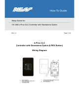
Stacklight: Indicates the state of the system.
Print Chamber Area: There are two doors in
front of the Print Chamber—the outer locking
door, and the inner print chamber door. The
parts are printed inside the Print Chamber.
E-Stop: The Emergency Stop button is a
safety mechanism used to shut off the
machine in an emergency situation in which it
cannot be shut down in the usual manner.
User Interface (UI): The user controls the
system using a touchscreen located on the
front panel.
LED Interface Lights and Controls: There
are three LED lights which give the user visual
feedback regarding the system. The two
buttons allow the user to control the chamber
lights and enable the system. There are two
standard USB ports beneath them.
User and Service Access Panels: There are
two types of panels on the sides and back of
the machine—user access and service
access. The user access panels are hinged
doors. The service access panels are lift-off
panels.
A
B
C
D
E
F

3D Systems, Inc.
8
ProX MATERIAL QUALITY CONTROL (MQC) SYSTEM
The MQC System is designed to be used as the material handling unit for the ProX 500 SLS line of printers. It is responsible for
delivering material to the printer, storing and mixing fresh and used material, and breaking out the SLS parts from the print cake which
is produced by the printer. One MQC System can handle material for up to two printers.
Blended Material Bin: Material which is a combination of used material and fresh material is stored for production use in
this hopper. The system handles this automatically.
Recyled Material Bin: Material which has gone through the system is stored here for production use. The used material
is reclaimed through the sifter. See letter ‘F’ below.
Fresh Material Input:
Fresh material is loaded at this location. The user must scan the material tag on the container
across the Reader (See letter ‘I’ below) to open the doors.
Breakout Controls: This wheel switch allows the user to turn the sifter on and off.
Reject Chute: Spent material (as determined by the user) is loaded into the reject chute.
Sifter: The user removes the parts from the print cake in the breakout area and places the material for reuse into the
sifter. After sifting, the material will be transported to the used material hopper.
Breakout Area: The print cake is brought here using the Part Transfer Cart Assembly.
Thermocouples: Two temperature gauges for the print cake used to determine whether or not the print cake has cooled
sufciently to break out the parts.
Nitrogen Cooling Lid: This lid is placed on top of a lled print cake extraction cylinder to control the cooldown of the print
cake when using nitrogen for cooling.
A
B
C
D
E
F
G
H
I
J
I
G
H
FED
BA
C
KL
MQC System – Front View

3D Systems, Inc.
9
Stowaway Area: Underneath the breakout area, there is a shelf which can be used to store part extraction cylinders when
they are not in use.
Tag Reader: The tag reader is used to scan the tag on the lid of the material container. This ensures that the system
keeps track of material quantity and fresh-to-new material ratios. The tag must be scanned to unlock the Fresh Material
Input doors and add the material to the system.
MQC System Operator Controls: User interface for operation of the MQC System.
J
K
L

3D Systems, Inc.
10
I
J
RJ45 Ethernet Connectors (3x): Network
connections to service up to 2 printers and a laptop
(for service personnel only).
3D Systems Nitrogen Generator Connection: If
you have purchased a Nitrogen Generator from 3D
Systems, it is connected here.
Oxygen Monitor Connection: A room oxygen
monitor is connected here.
Compressed Air (CDA) Inlet: Input for
compressed air coming into the MQC System.
Nitrogen Inlet: Input for nitrogen supply.
Material Output A: Material transfer connection for
Printer A.
A
B
C
D
E
F
MQC System – Rear View
A
B
C
D
E
F
G
H
Material Output B: Material transfer connection for
Printer B.
AC Inlet: Power connection for MQC System.
Dust Collector Port: Connection for the dust
collector.
2-Stage Hepa/Sock Filter: The material lter for the
MQC System.
G
H
I
J

3D Systems, Inc.
11
AUXILIARY SLS EQUIPMENT
There are several auxiliary components which can accompany the ProX 500 system. The Nitrogen Generator and Bead Blaster
(optional) are shown below.
Nitrogen Generator
3D Systems manufactures a High-Performance Nitrogen Generator
— Part Number 104011-02. The generator is ideal for SLS
applications.
Bead Blaster (Optional)
If you plan to use DuraForm SLS material, 3D Systems
recommends you install a pneumatic abrasive blast
cabinet (“bead blaster”) in the part nishing area separate
from the ProX 500 SLS 3D Printer process station room.
3D Systems
Nitrogen
Compressed
O
2
exhaust
N
2
outlet
O
2
exit

3D Systems, Inc.
12
ProX 500 SYSTEM COMPONENTS
Emergency Stop: This switch, located above the touchscreen, immediately disables all hazardous machine functions or
renders them safe. However, some surfaces may remain hot and care should be taken when handling them. After being
pressed, it remains in the closed state until it is manually returned to the open state.
User Interface: The user controls the system using a touchscreen located on the front panel.
Buttons, Indicators, USB Ports:
Chamber Lights: This button turns the chamber lighting on or off
LED Indicators:
The LED indicators under the touchscreen indicate the system’s power and safety status. Each indicator
operates as follows:
• “Laser” Blue LED
A
B
C
ProX 500 User Interface
The User Interface, located on the front panel of the printer, consists of a touchscreen and the system status LED indicators. An E-Stop
is located above the touchscreen.
B
C
A

3D Systems, Inc.
13
- ON, Solid
» Laser is enabled.
- OFF
» Laser is not enabled.
• “Control” Green LED
- ON, Solid
» System is on and its controller has initialized.
» The system is in RUN mode.
- OFF
» System is OFF or its controller is still initializing.
• “System” Amber LED
- ON, Solid
» All E-stop buttons are reset, and system power is enabled.
- OFF
» An E-stop button is pressed or system power is not enabled.
System Enable: This button re-enables the system following an emergency stop, which occurs after the emergency stop
switch returns to the open state.
USB: A standard auxiliary USB port connected to the control PC is located under the LED Indicators.

3D Systems, Inc.
14
Electrical Cabinet
Computer: A computer which handles
much of the functionality of the
touchscreen and printer is located
inside the electrical cabinet. It is
part of a wider system of electronic
components (Field-Programmable
Gate Arrays, Digital Signal Processors,
etc.) which control the hardware of the
system.
Main Power
Disconnect
Power Supply
Drop
Computer
Reset Button
ProX 500 Rear View
Power Supply:
This module distributes all the AC power that the system needs.
Circuits for the various subsystems are located in this module.
Main Power Disconnect: The main power
disconnect, located on the left side of the system,
enables you to turn on and off all power to the
system. Do NOT position the equipment so that it is
difcult to operate this device. There is a computer
reset button on the left side of the machine, that
the user may need to access in order to reboot the
software if it should become inoperable.
ProX 500 Computer

3D Systems, Inc.
15
ProX 500 Stack Lights
The stack lights let the user know from a distance what state the system is in. There is a stack light for both the
main system and the MQC System.
ProX 500 SLS System Stack Light Conditions
Light Color Solid Flashing Off
Red E-Stop condition System fault active Normal
Yellow System is in service mode
System warning active and/or
message present on touchscreen
E-Stop condition or
normal
Green Print job active
System Active, not printing, manual
operations possible
E-Stop condition or
normal
Part Transfer Cart Assembly
The print cake Extraction Cylinder, Part Transfer Tray and Part
Transfer Cart, are used to remove the print cake from the ProX 500 print
chamber and transport it to the MQC System. The system ships with the
cylinder and tray. The transfer cart is optional.
Part Transfer Cart
Part Transfer Tray Extraction Cylinder

3D Systems, Inc.
16
Power Switch: This switch enables and disables power to the MQC System.
LED Display: The display is operated using the Control Dial (see below). It gives the user access to all functionality of the
machine.
Emergency Stop Button: Depress the E-Stop button to cut off all power to the machine. This function is usually reserved for
situations where the machine cannot be stopped normally.
Control Dial: The user selects functions on the LED Display using this dial control.
A
B
C
D
MQC System User Interface
The User Interface, located on the front panel of the MQC System, consists of a dial-operated menu screen that allows the user to
access the functionality of the system. An E-Stop control is located to the right of the screen and the system power switch is located to
the left. For detailed information on the interface screens, refer to the section, “MQC System User Interface Settings” on page 48.
B C
D
A
MQC SYSTEM COMPONENTS
MQC System Stack Light Conditions
Light Color Solid Flashing Off
Red E-Stop condition System fault active Normal
Yellow System is in service mode
System warning active and/or
message present on user interface
E-Stop condition or
normal
Green
System is active. Printer
transports are enabled
System is active. Printer transports
are disabled
E-Stop condition or
normal

3D Systems, Inc.
17
Sifter Switch
The Sifter Switch is located next to the sifter. The user moves the switch to the up position to enable vibration of the sifter during
breakout. Move the switch to the bottom position to stop the sifter.
Fresh Material Input
The material input hatch takes fresh material from the user and feeds it to the MQC System. To unlock the hatch, the user must rst
swipe the tag of the material container across the tag reader.
Sifter
Tag Reader
Breakout
Area
Material Hatch
Thermocouple

3D Systems, Inc.
18
3
SAFETY GUIDELINES & INSTRUCTIONS
GENERAL GUIDELINES
Before using your SLS equipment, your company should have a safety program in place. The safety program should:
• Point out hazardous equipment, materials, and procedures.
• Explain what to do in case of an emergency.
• Provide information about the hazards of the equipment and materials in the form of Safety Data Sheets (SDS). The Safety Data
Sheets are provided with all materials supplied by 3D Systems.
All SLS equipment is designed with safety in mind. However, improper use, malfunctions, and excessive exposure could cause injury.
TRAINING AND INSTRUCTIONS
Follow these general safety guidelines when operating any SLS equipment:
• Do not operate any SLS equipment before receiving proper training.
• Read and follow all operating instructions.
• Follow all safety rules in this section and heed all hazard warnings in this guide.
• Do not try to perform any equipment maintenance procedures you were not trained to do.
• Operators are trained to operate the system and perform all the necessary tasks to print a part.
• Certied service personnel are those who have completed the 3D Systems service training package and are certied to
perform service tasks. Certication may occur at various levels, and servicers should only perform tasks they are authorized
and certied to complete.
MACHINE HANDLING
• Do not try to access, service, or adjust any components inside any SLS equipment enclosure.
• Do not try to open any panel or door while a machine is running.
• Do not access any area of the machine near the print chamber during printing.
• Use special caution when handling a heated print cake and when dealing with the heated, inert environment inside the SLS sys-
tem’s print chamber. Take note of all thermal hazard warning labels on the machines.
• Secure electrical cables and coolant hoses to prevent tripping.
MATERIAL HANDLING
• Do not use any material without rst reviewing its Safety Data Sheet (SDS).
• To prevent injury and equipment damage, be sure to follow all handling guidelines detailed in the appropriate Material Guide.
LASER
• Do not try to access, service, or adjust the laser system in any way.
• Do not enter any area displaying posted warning signs during open beam operations. Open beam operations refer to the laser,
and they only occur during service procedures.
ALARMS AND WARNINGS
• If you see an error, alarm, or warning message on any SLS equipment display, note the state of that machine’s stack light. Clear
the alarm, error, or warning message before resuming operation.
• Displayed error, alarm, or warning messages can result from unsafe practices, such as opening an enclosure door or panel when
equipment is powered up and running.

3D Systems, Inc.
19
SAFETY SYMBOLS AND DEFINITIONS
The following safety labels are posted at various points on the machine to indicate potentially hazardous conditions:
HOT SURFACES HAZARD: There are surfaces and materials in the vicinity that may be hot and could cause severe
burns.
LASER RADIATION HAZARD: Invisible laser radiation is accessible in the vicinity of this sign or behind the access
panel. Direct and scattered radiation can cause severe burns and blindness. Access panels are for service only and
should be opened only by certied service personnel.
ELECTRIC SHOCK HAZARD: High voltage electricity is accessible in the vicinity of this sign or behind the access
panel. High voltage can cause severe burns or death. Access panels are for service only and should be opened only
by certied service personnel or trained maintenance personnel.
CAUTION: Indicates something may happen that could cause loss of data, damage to equipment, or personal injury.
CRUSH HAZARD: Injury or death from crushing weight.
NOTCHED BELT ENTANGLEMENT: Injury or death from entanglement in notched pulley drive belt.

3D Systems, Inc.
20
FIRST AID SECTION – WHAT TO DO
In the case of an accident while using any SLS equipment, seek medical attention immediately. Use the following
guidelines for specic safety instances.
Burns
This equipment contains high temperatures and burning laser radiation which could cause 2
nd
degree burns. Do not attempt to remove
any protective panels. There are no user serviceable parts inside.
If a burn occurs, seek rst aid and immediate medical attention. Pushing the E-stop button will de-energize the equipment and diffuse
the hazardous situation.
Reporting Laser Radiation Exposure
If the injury was determined to be the result of laser radiation overexposure, please send a report to:
Attention: Laser Safety Ofcer
3D Systems, Inc.
333 Three D Systems Circle
Rock Hill, South Carolina, 29730
USA
Include the following information in your report:
• Nature of the accident and circumstances surrounding it
• Where the accident occurred
• Model and serial number of the machine
• Number of people involved
• Any other pertinent information
Please send this information to 3D Systems within a day of the accident.
Electrocution
The SLS system contains equipment energized at 208 volts, 3-phase delta. Do not attempt to remove protective panels. There are no
user serviceable parts inside.
If electrocution occurs, seek rst aid and medical attention immediately. Pushing the E-stop button will de-energize the equipment and
diffuse the hazardous situation.
Material Inhalation
The part cleaning process may create a choking or air restriction hazard. If someone has difculty breathing or a “loss of breath”
sensation, transport the person to a well-ventilated room or outside of the facility. If the condition persists, seek immediate medical
attention.
/