Legrand ezDALI Relay Module Installation guide
- Type
- Installation guide
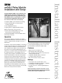
Legrand ezDALI Relay Module is a digital control device for non-DALI loads. It supports dual voltage operation (120/277 VAC), can handle up to 20 A of load, and draws only 7 mA from the DALI bus. The module is compatible with DALI ballast commands and features a zero-crossing circuitry that increases the relay's life by reducing inrush current. It is UL listed for plenum operation and may also be wired as a Class 2 device.
Legrand ezDALI Relay Module is a digital control device for non-DALI loads. It supports dual voltage operation (120/277 VAC), can handle up to 20 A of load, and draws only 7 mA from the DALI bus. The module is compatible with DALI ballast commands and features a zero-crossing circuitry that increases the relay's life by reducing inrush current. It is UL listed for plenum operation and may also be wired as a Class 2 device.


-
 1
1
-
 2
2


Legrand ezDALI Relay Module Installation guide
- Type
- Installation guide
Legrand ezDALI Relay Module is a digital control device for non-DALI loads. It supports dual voltage operation (120/277 VAC), can handle up to 20 A of load, and draws only 7 mA from the DALI bus. The module is compatible with DALI ballast commands and features a zero-crossing circuitry that increases the relay's life by reducing inrush current. It is UL listed for plenum operation and may also be wired as a Class 2 device.
Ask a question and I''ll find the answer in the document
Finding information in a document is now easier with AI
Related papers
-
Legrand WS-Install-DLCSS4_061004 (PDF) Installation guide
-
Legrand ezDALI Power Supply Installation guide
-
-
Legrand WS-Install-DSS4_061004 (PDF) Installation guide
-
-
-
-
-
-
Other documents
-
Dali CONNECT Stand M-600 Owner's manual
-
-
 AUTLED LC-004-944 User manual
-
Sunricher SR-2422K8-DIM-G1-S4 User manual
-
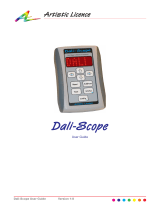 Artistic License Dali-Scope User manual
-
Acclaim Lighting PHAROS VLC Installation guide
-
 Artistric Licence Rail-DALI-DMX Quick start guide
-
ABB i-bus DALI-Gateway DG/S 8.1 User manual
-
Lutron Electronics EcoSystem T8 Digital Ballast Technical Manual
-


