Legrand Pass and Seymour C118WGAC Installation guide

Type
Installation guide
Auto/Clamp
®
Eliminates separate cable clamps as well as the tools
usually needed for installation. To install the cable, insert
stripped or non-stripped nonmetallic wire into the
Auto/Clamp
®
opening and pull through to the desired length.
The cable is automatically secured and the installation is
complete. There are no other operations for the electrician
to perform. Contractors can look forward to saving time
and money with every Auto/Clamp
®
plastic box installation.
(One cable per Auto Clamp)
Quick/Entry
®
Speeds installation by eliminating needs for tools.
Another time-saving idea is Quick/Entry
®
, a method that
allows you to push stripped or unstripped nonmetallic cable
into a single plastic box without removing knock-outs.
Jagged edges usually formed in other boxes are
eliminated.
(Multiple cables per Quick-Entry)
Quick/Click
®
Fast, easy and secure installations. The unique, labor
saving Quick/Click
®
design secures the wiring device quickly
and easily. Simply push in the mounting screws with a
screwdriver and turn the screw one or two turns.
With Quick/Click
®
mounting, you cannot cross-thread or
strip a device mounting screw.
Stabilizer
In a 2 x 4 application, the stablizer leg rests against the interi-
or surface of the opposing wall virtually eliminating inward
movement of the box.
Metal
Remove the rear stabilizing bar from its shipping position and
insert the long end into the slot located underneath the dry-
wall stop. For applications with wood studs, break off small
section of stabilizing bar where marked before insertion.
Integral
P122B is optimally sized for Steel studs only. All others may
be used with both steel and wood with little or no deflection.
PLASTIC BOXES
INSTALLATION INSTRUCTIONS
Auto/Clamp
®
clamping action
Just push cable
in and pull to
proper length.
Proper mounting
position of
stabilizing bar.
Wood and Steel Stud
Metal Bracket
1. A CT-1 Crimping Tool, is recommended for the installation
of these boxes to steel studs.
Place box flush against side of steel stud, at the required
height, as shown in Figure 1.
Note: If box is to be mounted to a wood stud, use two
holes in the bracket to mount the box with common nails.
2. Place CT-1 tool over flange of stud and box bracket as
shown in Figure 2. Set point of crimping tool spindle in
hole provided between crimping teeth of the bracket.
3. Press handles of crimping tool firmly until teeth on bracket
penetrate steel stud and curl to secure box firmly to the
stud.
4. Repeat steps 2 and 3 to secure the second set of teeth on
the bracket to the steel stud.
5. Multi-gang boxes are provided with a mounting bracket on
each side of the box so that one side can be nailed to a
wood stud or crimped to a steel stud. A phantom stud
(wood or steal) can then be mounted to the remaining
bracket on the box.
This phantom stud is nothing more than a short stud,
which once installed is pressed between the walls,
providing additional support for the box, as shown in
Figure 3.
Integral Plastic Bracket
Mount the box to the stud using two (2) screws (not included). Using the recommended type
of screw in conjunction with the countersunk mounting holes on the box allows for a truer
flush mount.
Recommended Screws: 1/2" minimum #6 flat head wood, drywall, or sheet metal screw.
Range and Dryer
For use with 30A - 60A flush mount receptacles. Factory installed internal cord clamp
accommodates 10 through 6 gauge wires.
Box Extender
Per NEC, “In walls or ceilings with a surface of concrete, tile, gypsum, plaster, or other non-
combustible material, boxes shall be installed so that the front edge of the box will not be set
back of the finished surface more than 6mm (1/4"). In walls and ceilings constructed of wood or
other combustible surface material, boxes shall be flush with the finished surface or project
therefrom.”
Pass & Seymour extension rings (available in 1 and 2 gang) are 1/4" thick and are stackable to
any desired thickness in 1/4" increments. A longer (#6-32) mounting screw may be required in
some applications.
Figure 3
Figure 2
Figure 1
Ceiling Box
1. Nail-On or J-Bracket types, just nail the ceiling box
accurately to the stud.
Note: The stud should rest on the built-in step (see
diagram) of the ceiling box to allow for flush mounting with
either 3/8" or 1/2" wallboard.
Bar-Hanger type, loosen both screws on bracket used to
secure box to hanger. Adjust bar hanger for either 16" or
24" joist spacing by aligning tab lock with proper slot. Fully
close tab lock with pliers until flush with bar surface. Nail
hanger to studs. Slide box to position desired and tighten
screws to secure box to hanger.
2. Auto/Clamps – Push nonmetallic cable (stripped or
unstripped) through the Auto/Clamp cable entry. Pull cable
to proper length.
3. When ceiling is finished, proceed to mount the lighting
fixture to the ceiling box, using the mounting strap supplied
with the fixture. Align the holes in the strap with the ceiling
box mounting holes.
4. Secure the lighting fixture to the mounting strap.
3-3/4" Round Ceiling and Wall Boxes
1. Cut a 3-3/4" round hole in the ceiling or wall using a hole saw.
2. Insert nonmetallic cable (stripped or unstripped) into the Auto/Clamp
®
cable entry.
3. Pull cable through to desired length. The cable is automatically secured without the need to
install separate clamps.
4. Insert the box into the hole and fasten using 3 - #6 screws that fully penetrate 3/8" trade size
or thicker plywood, or 7/16 trade size or thicker Oriented Strand Board (OSB), or 1/2" or
thicker solid wood.
Rating: 8 lbs. max. fixture rating when installed with 3 - #6 screws that fully penetrate 3/8"
trade size or thicker plywood, or 7/16 trade size or thicker Oriented Strand Board
(OSB), or 1/2" or thicker solid wood, for use on ceiling or walls. Not for fan support.
Low-Voltage Boxes and Divider
If you are installing video, telephone, or network wiring, you must use a low-voltage box or a
low-voltage divider to separate the low-voltage wiring from high-voltage electrical wiring.
Nail-On
J-Bracket
Bar-Hanger
See chart for
offset spacing.
Dia. Volume Offset Spacing
3-1/4 18 1-7/8 inch
4 20 1 inch
(continued on back)
P.O. Box 4822, Syracuse, NY 13221-4822 www.passandseymour.com (800-223-4185) Printed in USA
Old Work
Ceiling Boxes
1. Cut a 3-3/4" round hole in the ceiling using either a hole saw
or a hand saw (you may also place the back of the box against
the ceiling and draw a pencil line around it).
2. Insert nonmetallic cable (stripped or unstripped) into the
Auto/Clamp
®
cable entry.
3. Pull cable through to desired length. The cable is automatically
secured without the need to install separate clamps.
4. Insert the box into the ceiling with swing bracket flat to the
box. Turn screw clockwise with screwdriver, which will turn
the swing bracket to upright position, and tighten until snug
against the ceiling. (Swing out brackets permit installation of
box in ceilings 1-1/4" down to 1/8" thick).
Wall Boxes
1. See back of box for cut out dimensions (you may place back of
box against the wall and draw pencil line around it for template).
2. Insert nonmetallic cable (stripped or unstripped) into Auto/Clamp
®
cable entry.
3. Pull cable through to the desired length. The cable is
automatically secured – without having to install a separate clamp.
4. Insert box into the wall with swing bracket flat to the box. Turn
screw clockwise with screwdriver which will turn swing bracket
to upright position, and tighten till snug against wall. (Swing out
brackets permit installation of box in wall 1-1/4" thick down to
1/8" thick paneling).
P/N 340702 Rev. C
Low-Voltage Boxes and Divider (con’t.)
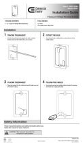
Old Work Style Directions:
1. Disconnect power to circuit by removing fuse or turn
circuit breakers OFF before removing cover plate.
2. Remove wall plate on existing device if you want
to line up new low voltage device next to it.
3. Line up edge with mounting screw on existing device.
4. Mark the areas shown.
5. Connect your marks using the inside edge of
the low voltage bracket as a straight edge.
(Cut out dimensions also listed on the front
of low voltage bracket.)
6. Cut a hole in the wall.
7. Insert low voltage bracket into the wall with
swing bracket flat to the box. Turn screw clockwise with screwdriver, which will turn
the swing bracket to upright position, and tighten till snug against wall. (Swing out brackets
permits installation of box in wall 1-1/4" thick down to 1/8" thick paneling.)
Warning – To prevent severe shock or electrocution, always turn power OFF at the service panel
before installing this unit, working on the circuit, or changing a lamp.
  • Page 1 1
  • Page 2 2
  • Page 3 3
  • Page 4 4

Legrand Pass and Seymour C118WGAC Installation guide

Type
Installation guide

Ask a question and I''ll find the answer in the document

Finding information in a document is now easier with AI