Page is loading ...

INSTALLATION INSTRUCTIONS: REV-A-MOTION
®
KIT FOR TOP MOUNT WASTE CONTAINERS
12400 Earl Jones Way
Louisville, KY 40299
rev-a-shelf.com
Customer Service: 800-626-1126
Faceframe Install pg. 2
Frameless Install pg. 5
REV-A-MOTION
®
KIT FOR TOP MOUNT WASTE CONTAINERS
TOOLS REQUIRED:
60 MIN
ESTIMATED ASSEMBLY TIME:
CARE AND MAINTENANCE:
INSTALLATION
Clean with a damp cloth and
wipe parts dry.
I-4WCTM-RM-0319
#2
Parts List
No. Description Qty
A Waste Container 1 or 2*
B Top Mount Wood Frame* 1
C Wood Bin** 1
D Adjustable Foot 1
E Rear Slide Assembly Strap for 18” and 21” Base 1
F Left & Right Side Mounting Brackets 2
G #8 x 5/8” Pan Head Deep Thread Screws 6
H #6 X 5/8” Flat Head Screws 6
I #8-32 X 1/2” Phillips Machine Screw 2
J #8-32 Washer 2
K M5 X 14mm Pan Head Machine Screw 8
L M5 Flat Washers 16
M M5 Nylock Nut 8
Mending Plate Hardware
No. Description Qty
N Mending Plate 2
O M5 x 16mm Phillips Machine Screws 8
P M5 Flat Washers 16
Q M5 Nylock Nut 8
R M6.3 x 14mm Euro Washer Head Screws 6
Door Mount Hardware
No. Description Qty
S #6 x 1/2”Flat Head Screws 6
T Double Sided Tape 2
#2
PH
8
mm
* Appearance may vary depending on model purchased
** Single units only
18” Base
21” Base
D. E.
A.
B.
F.C.
G.
H.
I.
Q.
K.
N.
J.
R.
L.
O.
S. T.
M.
P.

Customer Service: 800-626-1126 | rev-a-shelf.com
2
Remove the gas spring from the
unit by placing a at head screw
driver between the metal clip and
plastic hub. Gently pry to relieve
pressure by popping the clip out,
taking care to keep it intact
(See Figure 1).
PREPARING UNIT
FOR INSTALLATION
STEP 1
ATTACHING THE REAR
MOUNTING STRAP
STEP 3
NOTE: If rear cabinet wall is
less than 1/2” thick, the use of
a furring strip may be necessary
(See Figure 3.1).
Position the rear strap assembly
as shown in Figure 3.2. Be sure
it’s centered on the back wall and
elevated so the center slot of each
rear socket is positioned 17-15/16”
(50 qt. version) or 12-7/8” (35 qt.
version) from the cabinet oor
(See Figure 3.3).
Fasten the rear strap assembly
to the rear cabinet wall using the
(4) #8 x 5/8” pan head screws
provided. We recommend starting
with (2) screws in the center slots
in case adjustments are necessary
(See Figure 3.4).
NOTE: Make sure to adjust
the rear bracket dimensions
accordingly if you are using
system holes.
FIGURE 1
FIGURE 3.3
FIGURE 3.4
FIGURE 3.2FIGURE 3.1
FIGURE 2.2FIGURE 2.1
PUSH TO RELEASE
SLIDE OUT
EXTEND
SLIDE TO
REVEAL
TRIGGER
CENTER
Release the slides from the frame
by extending the slide as shown in
Figure 2.1, revealing the trigger.
Push the trigger as shown in
Figure 2.2 to release the slides.
STEP 2
FACE FRAME CABINET APPLICATION
#2
800-626-1126 | rev-a-shelf.com
2
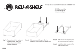
Pull slides away from wood
frame until they stop. Press the
black lever in the middle of the
slide to the opposite side and
pull slide to disconnect. (It may
take a little force to pull apart.)
See Fig. B
STEP 1
Install rear brackets to the
outer member of the slides
that you just removed. Make
sure the bend is facing the
inside of the slide as shown.
See Fig. C
STEP 2
FIG. C
Measure the distance from the
inside wall of your cabinet to
the opening and record. ((A) in
Fig. D)) You will need this num-
ber for step 6.
STEP 3
FIG. B
I-WCTMBBSC150-0315
INSTALLATION
INSTRUCTIONS
Top Mount Pull-Out Waste Containers
For models: 4WCTM-12BBSCDM1, 4WCTM-15BBSCDM2,
4WCTM-18BBSCDM2, 4WCTM-1550BBSCDM-1
and 4WCTM-2150BBSCDM-2
TOOLS REQUIRED:
ESTIMATED ASSEMBLY
TIME:
45 MIN
CARE AND MAINTENANCE:
CLEAN WITH A DAMP CLOTH
AND WIPE PARTS DRY.
WOVEN BASKET INSTALLATION INSTRUCTIONS
ESTIMATED ASSEMBLY TIME:
20 MIN
CARE AND MAINTENANCE:
Clean basket and wood frame with a damp cloth and wipe parts
dry. Machine wash liner in cold water with like colors.
2409 Plantside Dr., Jeersontown, KY 40299
800.626.1126
www.rev-a-shelf.com
1) Measure the inside cabinet width (ICW) at desired height for wood rails.
2) Measure the width of basket wood frame (BW).
3) Subtract BW from ICW. Divide answer by 2. Subtract 1/16” from answer.
This will give you the dimension needed from bottom of groove to back of wood
rail (ICW-BW) ÷ 2 - 1/16”.
4) Cut wood rails per steps 1-3.
5) Place rst cut rail in cabinet with front of rail against back of face frame (for
frameless cabinets, ush with front of cabinet.) at desired height. Secure the front
hole with proper size screw. (Screws not included due to variant in cabinet wall
thicknesses) (Make sure screw does not go through outside wall of cabinet).
Part list:
NOTE: SCREWS NOT INCLUDED DUETO VARIANT SIZES IN CABINETS
(ICW-BW) ÷ 2 - 1/16”
Desired Height
of Rail
Inside
Cabinet
Width
(ICW)
Basket
Width
(BW)
Bottom of groove
Back of wood rail
8) Install second rail on opposite side of cabinet per steps 5-6 at height
location from step 7.
7) Measure from oor of cabinet to bottom of installed rail.
6) Make sure rail is level, then secure to cabinet with screws at
remaining hole locations.
9) Slide in basket.
I-4WV-TRI-1013
Bottom of
rail to oor of
cabinet
Repeat steps for additional baskets.
Visit our YouTube Channel for an installation video of this product
Youtube.com/REVASHELF nd “Wood Top Mount”
1/16”
12400 Earl Jones Way, Louisville, KY 40299
(800) 626-1126 • www.rev-a-shelf.com
Step1: Install rear bracket to rear of slide.
19” 19”
INSTALLATION INSTRUCTIONS
for Top Mount Pull-Out Waste Containers
INSTRUCCIONES DE INSTALACIÓN
para cestos de basura deslizantes con montaje superior
NOTICE D’INSTALLATION
de la poubelle montée sur glissières supérieures
For models, Para los modelos, Pour les modèles:
4WCTM-12BBSCDM1, 4WCTM-15BBSCDM2,
4WCTM-18BBSCDM2, 4WCTM-1550BBSCDM-1
and 4WCTM-2150BBSCDM-2
Step 2:
Paso 2: Instale la parte delantera de la deslizadera en el bastidor
Étape 2: Monter l’avant de la glissière sur le cadre frontal. Le trou doit se
Step 5: Mount Rear Bracket. Extend the slide rear mounting bracket until it
cabinet wall at rear of slide as it is up front.
tighten. Tighten screw in front
bracket.
Paso 5: Monte el soporte trasero. Extienda el soporte trasero de la
deslizadera hasta que toque atrás (el listón trasero). La parte inferior de
distancia entre la parte posterior de la pared del
soporte de montaje trasero debe ser similar a la
frente. Introduzca el tornillo de montaje en la
el centro del soporte de montaje trasero y
soporte delantero.
Étape 5: Monter le support arrière. Étendre le support de montage arrière
de la glissière jusqu’à ce qu’il touche l’arrière (le tasseau). Le dessous de la
séparant le
support de montage arrière
Placer une vis de montage dans la fente
horizontale du centre du support
de montage arrière et la serrer. Serrer la vis du support avant.
Step 6: Install wood unit (with slides attached) into cabinet, engaging
product member slides into cabinet member slides push unit until it locks
in place.
Paso 6: Instale la pieza de madera (con las deslizaderas instaladas) en
el armario de forma que las deslizaderas en el producto se entren en las
deslizaderas que están en el
armario y empuje hasta que cierren.
Étape 6: Installer l’ensemble en bois (avec les glissières
montées) dans l’armoire en engageant les glissières du produit dans celles
de l’armoire. Pousser sur l’ensemble jusqu’à ce qu’il s’enclenche.
Step 1: Install rear bracket to rear of slide.
Paso 1: Instale el soporte trasero en la parte posterior de la deslizadera.
Étape 1: Attacher le support arrière à l’arrière de la glissière.
STEP 4:
Measure from inside
cabinet wall to inside
face frame (A) distance
should be measured
the same at rear of
cabinet (B).
STEP 6:
Install wood unit (with slides attached) into cabinet,
engaging product member slides into cabinet member
slides, push
unit until it
locks in place.
Now you are
ready to
mount the
door.
STEP 7:
See door mounting instructions on inside.
STEP 5:
Position the slide with front
bracket on the face frame
opening and move it forward
until the self register stop hits the
inside of the face frame opening.
Bottom of slide should be 13 1/2"
from cabinet floor. Install screw in
slotted mounting hole, do not
tighten. Extend the slide rear mounting bracket until it
contacts the rear Furring strip. Bottom of slide should be
13 1/2" from cabinet floor. Rear mounting bracket should
be the same distance from the side cabinet wall at rear of
slide as it is up front. Drive mounting screw in center
horizontal slot of rear mounting bracket, tighten.
Tighten screw in front bracket.
Face Frame
Cabinet Member
Slides
Furring Strips
Product Member Cabinet Member
Self
Register
Stop
Front View
(B)
Step 3: If rear of cabinet is thinner than ½”, install a ½” x 3” wide furring
Paso 3: Si el grosor de la parte trasera del armario es inferior a
13 mm (½ pulg.), instale un listón de
13 x 76 mm (½ x 3 pulg.) de ancho
centrada en la parte trasera y a 36cm
(14 ¼
pulg. - 35 y 27Qt. / 20 ⁄ - 50Qt.) del
Étape 3: Si l’arrière de l’armoire est
moins épais que 13 mm (½ po),
attacher un tasseau de
13mm x 76mm (½ x 3 po) à l’arrière de l’armoire,
centré à 36 cm (14-¼
po. - 33 et 25(L) / 20- ⁄ po. - 47(L)) du fond de l’armoire.
Step 4: Measure from inside cabinet wall to inside face frame (A) distance
should be measured the same at rear of cabinet (B).
Paso 4: La medida de la pared interior del
STEP 1:
Install front bracket to
front side of slide.
STEP 2:
Install rear bracket to
rear of slide.
STEP 3:
Mount slide to cabinet
if rear of cabinet is
thinner then 1/2" install
a 1/2" x 3" wide furring
strip to the back of the
cabinet centered
14 1/4" from floor of
cabinet.
STEP 4:
Measure from inside
cabinet wall to inside
face frame (A) distance
should be measured
the same at rear of
cabinet (B).
STEP 6:
Install wood unit (with slides attached) into cabinet,
engaging product member slides into cabinet member
slides, push
unit until it
locks in place.
Now you are
ready to
mount the
door.
STEP 7:
See door mounting instructions on inside.
14
1
/4"
13
1
/2"
STEP 5:
Position the slide with front
bracket on the face frame
opening and move it forward
until the self register stop hits the
inside of the face frame opening.
Bottom of slide should be 13 1/2"
from cabinet floor. Install screw in
slotted mounting hole, do not
tighten. Extend the slide rear mounting bracket until it
contacts the rear Furring strip. Bottom of slide should be
13 1/2" from cabinet floor. Rear mounting bracket should
be the same distance from the side cabinet wall at rear of
slide as it is up front. Drive mounting screw in center
horizontal slot of rear mounting bracket, tighten.
Tighten screw in front bracket.
Face Frame
Cabinet Member
Slides
Furring Strips
Furring
Strips
Product Member Cabinet Member
Self
Register
Stop
14
1
/4"
13
1
/2" 13
1
/2"
Front View
Top View
(A)
(B)
armario a la parte
interior del bastidor delantero
(A) debe ser similar en la parte
posterior del armario (B).
Étape 4: Mesurer à partir
de la paroi intérieure de
l’armoire jusqu’à l’intérieur du
cadre frontal (A). Mesurer la
même distance à l’arrière de
l’armoire (B).
14¼”
Face Frame
12¾”
14¼”
- 35Qt. & 27Qt. / 19” - 50Qt.
-
35 y 27Qt. / 19” -
50Qt.
- 35 y 27Qt./ 19”-50Qt.)
e
e
(
- 35Qt. & 27Qt. / 20 ⁄ - 50Qt.
(
13 ⁄ ” - 35 & 27Qt.
-
19” - 50Qt. g
Drive mounting screw in center
horizontal slot of rear mounting bracket,
ce
de la paroi latérale de l’armoire doit être identique à l’arrière et à l’avant.
c
d
g
Step 7: Mount Door...See separate instructions sheet included.
Paso 7: Monte la puerta de acuerdo a las instrucciones que están en el
instructivo separado adjunto.
Étape 7: Montage de la porte : voir la notice de montage séparée.
I-WCTMBBSC150-0115
27Qt./
35Qt.
50Qt.
piso del armario.
armario a la deslizadera del
que tiene con respecto al
ranura horizontal que está en
apriételo. Apriete el tornillo en el
. - 33 et 25(L) / 19” po. - 47(L))
. - 3 3 et 25 (L) / 19 po.-
47(L))
(
(
(
(
(
f
12400 Earl Jones Way, Louisville, KY 40299
(800) 626-1126 • www.rev-a-shelf.com
19” 19”
INSTALLATION INSTRUCTIONS
for Top Mount Pull-Out Waste Containers
INSTRUCCIONES DE INSTALACIÓN
para cestos de basura deslizantes con montaje superior
NOTICE D’INSTALLATION
de la poubelle montée sur glissières supérieures
For models, Para los modelos, Pour les modèles:
4WCTM-12BBSCDM1, 4WCTM-15BBSCDM2,
4WCTM-18BBSCDM2, 4WCTM-1550BBSCDM-1
and 4WCTM-2150BBSCDM-2
Step 2:
Paso 2: Instale la parte delantera de la deslizadera en el bastidor
Étape 2: Monter l’avant de la glissière sur le cadre frontal. Le trou doit se
Step 5:
Mount Rear Bracket. Extend the slide rear mounting bracket until it
cabinet wall at rear of slide as it is up front.
tighten. Tighten screw in front
bracket.
Paso 5: Monte el soporte trasero. Extienda el soporte trasero de la
deslizadera hasta que toque atrás (el listón trasero). La parte inferior de
distancia entre la parte posterior de la pared del
soporte de montaje trasero debe ser similar a la
frente. Introduzca el tornillo de montaje en la
el centro del soporte de montaje trasero y
soporte delantero.
Étape 5: Monter le support arrière. Étendre le support de montage arrière
de la glissière jusqu’à ce qu’il touche l’arrière (le tasseau). Le dessous de la
séparant le
support de montage arrière
Placer une vis de montage dans la fente
horizontale du centre du support
de montage arrière et la serrer. Serrer la vis du support avant.
Step 6: Install wood unit (with slides attached) into cabinet, engaging
product member slides into cabinet member slides push unit until it locks
in place.
Paso 6: Instale la pieza de madera (con las deslizaderas instaladas) en
el armario de forma que las deslizaderas en el producto se entren en las
deslizaderas que están en el
armario y empuje hasta que cierren.
Étape 6: Installer l’ensemble en bois (avec les glissières
montées) dans l’armoire en engageant les glissières du produit dans celles
de l’armoire. Pousser sur l’ensemble jusqu’à ce qu’il s’enclenche.
Step 1: Install rear bracket to rear of slide.
Paso 1: Instale el soporte trasero en la parte posterior de la deslizadera.
Étape 1: Attacher le support arrière à l’arrière de la glissière.
STEP 4:
Measure from inside
cabinet wall to inside
face frame (A) distance
should be measured
the same at rear of
cabinet (B).
STEP 6:
Install wood unit (with slides attached) into cabinet,
engaging product member slides into cabinet member
slides, push
unit until it
locks in place.
Now you are
ready to
mount the
door.
STEP 7:
See door mounting instructions on inside.
STEP 5:
Position the slide with front
bracket on the face frame
opening and move it forward
until the self register stop hits the
inside of the face frame opening.
Bottom of slide should be 13 1/2"
from cabinet floor. Install screw in
slotted mounting hole, do not
tighten. Extend the slide rear mounting bracket until it
contacts the rear Furring strip. Bottom of slide should be
13 1/2" from cabinet floor. Rear mounting bracket should
be the same distance from the side cabinet wall at rear of
slide as it is up front. Drive mounting screw in center
horizontal slot of rear mounting bracket, tighten.
Tighten screw in front bracket.
Face Frame
Cabinet Member
Slides
Furring Strips
Product Member Cabinet Member
Self
Register
Stop
Front View
(B)
Step 3: If rear of cabinet is thinner than ½”, install a ½” x 3” wide furring
Paso 3: Si el grosor de la parte trasera del armario es inferior a
13 mm (½ pulg.), instale un listón de
13 x 76 mm (½ x 3 pulg.) de ancho
centrada en la parte trasera y a 36cm
(14 ¼
pulg. - 35 y 27Qt. / 20 ⁄ - 50Qt.) del
Étape 3: Si l’arrière de l’armoire est
moins épais que 13 mm (½ po),
attacher un tasseau de
13mm x 76mm (½ x 3 po) à l’arrière de l’armoire,
centré à 36 cm (14-¼
po. - 33 et 25(L) / 20- ⁄ po. - 47(L)) du fond de l’armoire.
Step 4: Measure from inside cabinet wall to inside face frame (A) distance
should be measured the same at rear of cabinet (B).
Paso 4: La medida de la pared interior del
STEP 1:
Install front bracket to
front side of slide.
STEP 2:
Install rear bracket to
rear of slide.
STEP 3:
Mount slide to cabinet
if rear of cabinet is
thinner then 1/2" install
a 1/2" x 3" wide furring
strip to the back of the
cabinet centered
14 1/4" from floor of
cabinet.
STEP 4:
Measure from inside
cabinet wall to inside
face frame (A) distance
should be measured
the same at rear of
cabinet (B).
STEP 6:
Install wood unit (with slides attached) into cabinet,
engaging product member slides into cabinet member
slides, push
unit until it
locks in place.
Now you are
ready to
mount the
door.
STEP 7:
See door mounting instructions on inside.
14
1
/4"
13
1
/2"
STEP 5:
Position the slide with front
bracket on the face frame
opening and move it forward
until the self register stop hits the
inside of the face frame opening.
Bottom of slide should be 13 1/2"
from cabinet floor. Install screw in
slotted mounting hole, do not
tighten. Extend the slide rear mounting bracket until it
contacts the rear Furring strip. Bottom of slide should be
13 1/2" from cabinet floor. Rear mounting bracket should
be the same distance from the side cabinet wall at rear of
slide as it is up front. Drive mounting screw in center
horizontal slot of rear mounting bracket, tighten.
Tighten screw in front bracket.
Face Frame
Cabinet Member
Slides
Furring Strips
Furring
Strips
Product Member Cabinet Member
Self
Register
Stop
14
1
/4"
13
1
/2" 13
1
/2"
Front View
Top View
(A)
(B)
armario a la parte
interior del bastidor delantero
(A) debe ser similar en la parte
posterior del armario (B).
Étape 4: Mesurer à partir
de la paroi intérieure de
l’armoire jusqu’à l’intérieur du
cadre frontal (A). Mesurer la
même distance à l’arrière de
l’armoire (B).
14¼”
Face Frame
12¾”
14¼”
- 35Qt. & 27Qt. / 19” - 50Qt.
-
35 y 27Qt. / 19” -
50Qt.
- 35 y 27Qt./ 19”-50Qt.)
e
e
(
- 35Qt. & 27Qt. / 20 ⁄ - 50Qt.
(
13 ⁄ ” - 35 & 27Qt.
-
19” - 50Qt. g
Drive mounting screw in center
horizontal slot of rear mounting bracket,
ce
de la paroi latérale de l’armoire doit être identique à l’arrière et à l’avant.
c
d
g
Step 7: Mount Door...See separate instructions sheet included.
Paso 7: Monte la puerta de acuerdo a las instrucciones que están en el
instructivo separado adjunto.
Étape 7: Montage de la porte : voir la notice de montage séparée.
I-WCTMBBSC150-0115
27Qt./
35Qt.
50Qt.
piso del armario.
armario a la deslizadera del
que tiene con respecto al
ranura horizontal que está en
apriételo. Apriete el tornillo en el
. - 33 et 25(L) / 19” po. - 47(L))
. - 3 3 et 25 (L) / 19 po.-
47(L))
(
(
(
(
(
f
12400 Earl Jones Way, Louisville, KY 40299
(800) 626-1126 • www.rev-a-shelf.com
19” 19”
INSTALLATION INSTRUCTIONS
for Top Mount Pull-Out Waste Containers
INSTRUCCIONES DE INSTALACIÓN
para cestos de basura deslizantes con montaje superior
NOTICE D’INSTALLATION
de la poubelle montée sur glissières supérieures
For models, Para los modelos, Pour les modèles:
4WCTM-12BBSCDM1, 4WCTM-15BBSCDM2,
4WCTM-18BBSCDM2, 4WCTM-1550BBSCDM-1
and 4WCTM-2150BBSCDM-2
Step 2:
Paso 2: Instale la parte delantera de la deslizadera en el bastidor
Étape 2: Monter l’avant de la glissière sur le cadre frontal. Le trou doit se
Step 5: Mount Rear Bracket. Extend the slide rear mounting bracket until it
cabinet wall at rear of slide as it is up front.
tighten. Tighten screw in front
bracket.
Paso 5: Monte el soporte trasero. Extienda el soporte trasero de la
deslizadera hasta que toque atrás (el listón trasero). La parte inferior de
distancia entre la parte posterior de la pared del
soporte de montaje trasero debe ser similar a la
frente. Introduzca el tornillo de montaje en la
el centro del soporte de montaje trasero y
soporte delantero.
Étape 5: Monter le support arrière. Étendre le support de montage arrière
de la glissière jusqu’à ce qu’il touche l’arrière (le tasseau). Le dessous de la
séparant le
support de montage arrière
Placer une vis de montage dans la fente
horizontale du centre du support
de montage arrière et la serrer. Serrer la vis du support avant.
Step 6: Install wood unit (with slides attached) into cabinet, engaging
product member slides into cabinet member slides push unit until it locks
in place.
Paso 6: Instale la pieza de madera (con las deslizaderas instaladas) en
el armario de forma que las deslizaderas en el producto se entren en las
deslizaderas que están en el
armario y empuje hasta que cierren.
Étape 6: Installer l’ensemble en bois (avec les glissières
montées) dans l’armoire en engageant les glissières du produit dans celles
de l’armoire. Pousser sur l’ensemble jusqu’à ce qu’il s’enclenche.
Step 1: Install rear bracket to rear of slide.
Paso 1: Instale el soporte trasero en la parte posterior de la deslizadera.
Étape 1: Attacher le support arrière à l’arrière de la glissière.
STEP 4:
Measure from inside
cabinet wall to inside
face frame (A) distance
should be measured
the same at rear of
cabinet (B).
STEP 6:
Install wood unit (with slides attached) into cabinet,
engaging product member slides into cabinet member
slides, push
unit until it
locks in place.
Now you are
ready to
mount the
door.
STEP 7:
See door mounting instructions on inside.
STEP 5:
Position the slide with front
bracket on the face frame
opening and move it forward
until the self register stop hits the
inside of the face frame opening.
Bottom of slide should be 13 1/2"
from cabinet floor. Install screw in
slotted mounting hole, do not
tighten. Extend the slide rear mounting bracket until it
contacts the rear Furring strip. Bottom of slide should be
13 1/2" from cabinet floor. Rear mounting bracket should
be the same distance from the side cabinet wall at rear of
slide as it is up front. Drive mounting screw in center
horizontal slot of rear mounting bracket, tighten.
Tighten screw in front bracket.
Face Frame
Cabinet Member
Slides
Furring Strips
Product Member Cabinet Member
Self
Register
Stop
Front View
(B)
Step 3: If rear of cabinet is thinner than ½”, install a ½” x 3” wide furring
Paso 3: Si el grosor de la parte trasera del armario es inferior a
13 mm (½ pulg.), instale un listón de
13 x 76 mm (½ x 3 pulg.) de ancho
centrada en la parte trasera y a 36cm
(14 ¼
pulg. - 35 y 27Qt. / 20 ⁄ - 50Qt.) del
Étape 3: Si l’arrière de l’armoire est
moins épais que 13 mm (½ po),
attacher un tasseau de
13mm x 76mm (½ x 3 po) à l’arrière de l’armoire,
centré à 36 cm (14-¼
po. - 33 et 25(L) / 20- ⁄ po. - 47(L)) du fond de l’armoire.
Step 4: Measure from inside cabinet wall to inside face frame (A) distance
should be measured the same at rear of cabinet (B).
Paso 4: La medida de la pared interior del
STEP 1:
Install front bracket to
front side of slide.
STEP 2:
Install rear bracket to
rear of slide.
STEP 3:
Mount slide to cabinet
if rear of cabinet is
thinner then 1/2" install
a 1/2" x 3" wide furring
strip to the back of the
cabinet centered
14 1/4" from floor of
cabinet.
STEP 4:
Measure from inside
cabinet wall to inside
face frame (A) distance
should be measured
the same at rear of
cabinet (B).
STEP 6:
Install wood unit (with slides attached) into cabinet,
engaging product member slides into cabinet member
slides, push
unit until it
locks in place.
Now you are
ready to
mount the
door.
STEP 7:
See door mounting instructions on inside.
14
1
/4"
13
1
/2"
STEP 5:
Position the slide with front
bracket on the face frame
opening and move it forward
until the self register stop hits the
inside of the face frame opening.
Bottom of slide should be 13 1/2"
from cabinet floor. Install screw in
slotted mounting hole, do not
tighten. Extend the slide rear mounting bracket until it
contacts the rear Furring strip. Bottom of slide should be
13 1/2" from cabinet floor. Rear mounting bracket should
be the same distance from the side cabinet wall at rear of
slide as it is up front. Drive mounting screw in center
horizontal slot of rear mounting bracket, tighten.
Tighten screw in front bracket.
Face Frame
Cabinet Member
Slides
Furring Strips
Furring
Strips
Product Member Cabinet Member
Self
Register
Stop
14
1
/4"
13
1
/2" 13
1
/2"
Front View
Top View
(A)
(B)
armario a la parte
interior del bastidor delantero
(A) debe ser similar en la parte
posterior del armario (B).
Étape 4: Mesurer à partir
de la paroi intérieure de
l’armoire jusqu’à l’intérieur du
cadre frontal (A). Mesurer la
même distance à l’arrière de
l’armoire (B).
14¼”
Face Frame
12¾”
14¼”
- 35Qt. & 27Qt. / 19” - 50Qt.
-
35 y 27Qt. / 19” -
50Qt.
- 35 y 27Qt./ 19”-50Qt.)
e
e
(
- 35Qt. & 27Qt. / 20 ⁄ - 50Qt.
(
13 ⁄ ” - 35 & 27Qt.
-
19” - 50Qt. g
Drive mounting screw in center
horizontal slot of rear mounting bracket,
ce
de la paroi latérale de l’armoire doit être identique à l’arrière et à l’avant.
c
d
g
Step 7: Mount Door...See separate instructions sheet included.
Paso 7: Monte la puerta de acuerdo a las instrucciones que están en el
instructivo separado adjunto.
Étape 7: Montage de la porte : voir la notice de montage séparée.
I-WCTMBBSC150-0115
27Qt./
35Qt.
50Qt.
piso del armario.
armario a la deslizadera del
que tiene con respecto al
ranura horizontal que está en
apriételo. Apriete el tornillo en el
. - 33 et 25(L) / 19” po. - 47(L))
. - 3 3 et 25 (L) / 19 po.-
47(L))
(
(
(
(
(
f
12400 Earl Jones Way, Louisville, KY 40299
(800) 626-1126 • www.rev-a-shelf.com
Download and Tips & Tricks Sheet at: Rev-a-shelf.com/TIPS_WCTMBBSC.pdf
Step7: Mount Door, see next page
For more information visit out YouTube channel or download
our “Tips and Tricks” sheet.
FIG. D
1
4
1
8
1
16
3
8
3
32
7
64
#2 #1
5
16
5
8
1
2
3
8
2” 1”
90˚
CABINET FRONT
CABINET BACK
DIM A
17-15/16” (50 QT.)
12-7/8” (35 QT.)
APPLY FURRING
STRIP IF
NECESSARY
#2
PH

INSTALLATION INSTRUCTIONS: REV-A-MOTION
®
KIT FOR TOP MOUNT WASTE CONTAINERS
3
NOTE: For Face Frame
applications, the product
member bracket and the side
mounting bracket are needed.
The mending plate is only needed
for Frameless applications
(See Figure 4.1).
Please refer to Figure 4.2 and
the table in Figure 4.3 for proper
order placement of the M5 Nylock
nuts, M5 x 14mm screws, and M5
washers.
FIGURE 4.1
FIGURE 4.3
SIDE MOUNTING BRACKET
PRODUCT
MEMBER
BRACKET
ASSEMBLING SIDE
MOUNTING BRACKETS
STEP 4
17-15/16” (50 qt.)
12-7/8” (35 qt.)
Face Frame Cabinet Installation
Step 1A Preparing the Unit for installation
Remove the Gas Spring from the unit.
This is done by removing the two retainer clips from each of the ball sockets and then
popping the spring ends from the ball studs. (SEE FIGURE 1A)
Disengage the cabinet members from the unit by pressing the release levers on the 2
slides and pulling them away from the product members. (SEE FIGURE 1A)
Step 2A Attaching Rear Mounting Strap
Fasten the rear strap assembly to the rear cabinet wall using the (4) #8 x 5/8” pan head
screws provided. The CENTER slot of each rear socket should be positioned 17-15/16”
(for 50 qt. frames) or 12-7/8” (for 35 qt. frames) from the floor of the cabinet as shown
in FIGURE 2A. It is best to start with two screws in the center slots in case adjustments
are necessary. Make sure to center the strap assembly left to right according to the
opening of the face frame. (SEE FIG 2A)
Note: If rear of cabinet is thinner than ½”, a furring strip should be used between the
back wall and the mounting strap to ensure the rear mounting strap is properly attached.
Keep in mind the minimum depth required is 21-3/4” and is measured from the back
of the door.
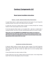
Step 3A Assembling Side Mounting Brackets
For face frame applications, only the product member bracket and the side
mounting bracket are necessary. (SEE FIGURE 3A)
Please refer to Table A for the proper hole alignment. If the table does not
apply to the cabinet in use, the outer slots will provide a fully adjustable
option to fit virtually any opening. Fasten the brackets according to table A
using the M5 nuts, bolts, and washers provided.
Step 4A Attaching Slides to Cabinet
While supporting the front of the side mounting bracket engage the back of the slide
with the rear strap assembly by sliding it into the outer socket of the assembly. The
product member should be pushed into the rear strap assembly until the front of each
product member and each side-mounting bracket is flush with the front of the face
frame. This is a press fit and there will be resistance. (SEE FIGURE 4A)
Continue to support the front of the slide. Do not let it fall as it may damage the rear
strap assembly.
Locate the bottom of the side-mounting bracket 15 ¾” (for 50 qt. frames) or 10-11/16”
(for 35 qt. frames) from the floor of the cabinet. Attach each bracket to the inside of
the face frame using the (3) #6 x 5/8” flat head screws provided. (SEE FIGURE 5A)
Note: it is recommended to pre-drill using a 3/32” drill bit
PROCEED TO STEP 6
FIGURE 2A
FIGURE 5A
CABINET MEMBER
HOLE LOCATION
PRODUCT MEMBER
HOLE LOCATION
MENDING PLATE
HOLE LOCATION
CABINET MEMBER
HOLE LOCATION
PRODUCT MEMBER
HOLE LOCATION
MENDING PLATE
HOLE LOCATION
1.5" Face Frame
C
C
N/A
1.625" Face Frame
B
B
N/A
1.75" Face Frame
A
A
N/A
Frameless with .75" Wall
B
A
2 & 5
Frameless with .708" Wall
B
D
1 & 8
Frameless with .625" Wall
B
B
3 & 6
Shimmed Inset Door 1.5" FF
C
C
N/A
Shimmed Inset Door 1.625" FF
B
B
N/A
Shimmed Inset Door 1.75" FF
A
A
N/A
FIGURE 1A
FIGURE 4A
1-1/2” Face Frame Example
-Product Member Top
-Side Mount Brkt Bottom
INSTALLATION INSTRUCTIONS
For Full Height Top Mount Waste Containers
With Rev-A-Motion
For face frame style cabinets see steps 1A-4A
For frameless style cabinets see steps 1B-5B
For cabinets with inset doors see steps 1C-4C
SIDE MOUNTING BRACKET
HOLE LOCATION
PRODUCT MEMBER
HOLE LOCATION
1-1/2” FACE FRAME C C
1-5/8” FACE FRAME B B
1-3/4” FACE FRAME A A
FIGURE 5.1 FIGURE 5.2
FIGURE 4.2
ATTACHING THE SLIDES
TO THE CABINET
STEP 5
Locate the bottom of the side
mounting bracket and place at
15-3/4” (50 qt. version) or
10-11/16” (35 qt. version) from
bottom of the face frame
(See Figure 5.1 & 5.2).
NOTE: Pre-drilling is
recommended when drilling into
the cabinet face frame to prevent
potential wood damages.
15-3/4” (50 QT.)
10-11/16” (35 QT.)
SCAB BOARD
15-3/4” (50 QT.)
10-11/16” (35 QT.)
FOR OVERLAY DOORS
THE FRONT EDGE OF THE SIDE
MOUNTING BRACKET SHOULD BE
FLUSH WITH THE FACE FRAME OF
THE CABINET.
FOR INSET DOORS
USING A SCAB BOARD (MINIMUM DEPTH 6”), FLUSH
THE CABINET SIDE WALLS WITH THE BACK OF THE
FACE FRAME. THE BACK OF YOUR FACE FRAME IS
NOW THE FRONT OF YOUR CABINET (SEE FIG 5.2).
! !
FIGURE 6
While supporting the front of the
side mounting bracket, engage
the back of the slide with the rear
strap assembly by sliding it into the
outer socket of the assembly. The
product member should be pushed
into the rear strap assembly until
the front of each product member
and each side mounting bracket
is ush with the front of the face
frame. This is a press t and there
will be resistance (See Fig 6).
Continue to support the front of
the slide.
NOTE: Do not let it fall as it may
damage the rear strap assembly.
STEP 6
OVERLAY DOORS INSET DOORS
8
mm

Customer Service: 800-626-1126 | rev-a-shelf.com
4
FIGURE 9
Retainer Clip
RE-ENGAGE UNIT
Re-engage the unit into each of
the cabinet members, ensuring the
slides are aligned properly
(See Fig 8). Once engaged, fully
cycle the unit a few times to ensure
proper slide operation.
STEP 8
Attach each side mounting bracket
to the inside of the face frame
using the (6) provided #6 x 5/8”
at head screws (See Fig 7).
STEP 7
Re-install the gas spring while
making sure that the gas reservoir
is attached to the top stud as
shown in Fig 9. Make sure to install
both of the retainer clips into each
of the stud caps.
STEP 9
At this time, proceed to page 8
and continue your installation.
STEP 10
FIGURE 7
FIGURE 8
#2

INSTALLATION INSTRUCTIONS: REV-A-MOTION
®
KIT FOR TOP MOUNT WASTE CONTAINERS
5
FRAMELESS CABINET APPLICATION
ATTACHING THE REAR
MOUNTING STRAP
STEP 3
NOTE: If rear cabinet wall is less than
1/2” thick, the use of a furring strip
may be necessary (See Fig 3.1).
Position the rear strap assembly as
shown in Fig 3.2. Be sure it’s centered
on the back wall and elevated so
the center slot of each rear socket is
positioned 17-15/16” (50 qt. version) or
12-7/8” (35 qt. version) from the cabinet
oor (See Fig 3.3).
Fasten the rear strap assembly to the
rear cabinet wall using the (4) #8 x
5/8” pan head screws provided. We
recommend starting with (2) screws in
the center slots in case adjustments are
necessary.
NOTE: Make sure to adjust the rear
bracket dimensions accordingly if you
are using system holes.
#2
PH
FIGURE 3.2
FIGURE 3.3 FIGURE 3.4
FIGURE 3.1
CENTER
APPLY FURRING
STRIP IF
NECESSARY
17-15/16” (50 QT.)
12-7/8” (35 QT.)
FIGURE 2.2
FIGURE 2.1
FIGURE 1
PUSH TO RELEASE
SLIDE OUT
EXTEND
SLIDE TO
REVEAL
TRIGGER
800-626-1126 | rev-a-shelf.com
2
Pull slides away from wood
frame until they stop. Press the
black lever in the middle of the
slide to the opposite side and
pull slide to disconnect. (It may
take a little force to pull apart.)
See Fig. B
STEP 1
Install rear brackets to the
outer member of the slides
that you just removed. Make
sure the bend is facing the
inside of the slide as shown.
See Fig. C
STEP 2
FIG. C
Measure the distance from the
inside wall of your cabinet to
the opening and record. ((A) in
Fig. D)) You will need this num-
ber for step 6.
STEP 3
FIG. B
I-WCTMBBSC150-0315
INSTALLATION
INSTRUCTIONS
Top Mount Pull-Out Waste Containers
For models: 4WCTM-12BBSCDM1, 4WCTM-15BBSCDM2,
4WCTM-18BBSCDM2, 4WCTM-1550BBSCDM-1
and 4WCTM-2150BBSCDM-2
TOOLS REQUIRED:
ESTIMATED ASSEMBLY
TIME:
45 MIN
CARE AND MAINTENANCE:
CLEAN WITH A DAMP CLOTH
AND WIPE PARTS DRY.
WOVEN BASKET INSTALLATION INSTRUCTIONS
ESTIMATED ASSEMBLY TIME:
20 MIN
CARE AND MAINTENANCE:
Clean basket and wood frame with a damp cloth and wipe parts
dry. Machine wash liner in cold water with like colors.
2409 Plantside Dr., Jeersontown, KY 40299
800.626.1126
www.rev-a-shelf.com
1) Measure the inside cabinet width (ICW) at desired height for wood rails.
2) Measure the width of basket wood frame (BW).
3) Subtract BW from ICW. Divide answer by 2. Subtract 1/16” from answer.
This will give you the dimension needed from bottom of groove to back of wood
rail (ICW-BW) ÷ 2 - 1/16”.
4) Cut wood rails per steps 1-3.
5) Place rst cut rail in cabinet with front of rail against back of face frame (for
frameless cabinets, ush with front of cabinet.) at desired height. Secure the front
hole with proper size screw. (Screws not included due to variant in cabinet wall
thicknesses) (Make sure screw does not go through outside wall of cabinet).
Part list:
NOTE: SCREWS NOT INCLUDED DUETO VARIANT SIZES IN CABINETS
(ICW-BW) ÷ 2 - 1/16”
Desired Height
of Rail
Inside
Cabinet
Width
(ICW)
Basket
Width
(BW)
Bottom of groove
Back of wood rail
8) Install second rail on opposite side of cabinet per steps 5-6 at height
location from step 7.
7) Measure from oor of cabinet to bottom of installed rail.
6) Make sure rail is level, then secure to cabinet with screws at
remaining hole locations.
9) Slide in basket.
I-4WV-TRI-1013
Bottom of
rail to oor of
cabinet
Repeat steps for additional baskets.
Visit our YouTube Channel for an installation video of this product
Youtube.com/REVASHELF nd “Wood Top Mount”
1/16”
12400 Earl Jones Way, Louisville, KY 40299
(800) 626-1126 • www.rev-a-shelf.com
Step1: Install rear bracket to rear of slide.
19” 19”
INSTALLATION INSTRUCTIONS
for Top Mount Pull-Out Waste Containers
INSTRUCCIONES DE INSTALACIÓN
para cestos de basura deslizantes con montaje superior
NOTICE D’INSTALLATION
de la poubelle montée sur glissières supérieures
For models, Para los modelos, Pour les modèles:
4WCTM-12BBSCDM1, 4WCTM-15BBSCDM2,
4WCTM-18BBSCDM2, 4WCTM-1550BBSCDM-1
and 4WCTM-2150BBSCDM-2
Step 2:
Paso 2: Instale la parte delantera de la deslizadera en el bastidor
Étape 2: Monter l’avant de la glissière sur le cadre frontal. Le trou doit se
Step 5: Mount Rear Bracket. Extend the slide rear mounting bracket until it
cabinet wall at rear of slide as it is up front.
tighten. Tighten screw in front
bracket.
Paso 5: Monte el soporte trasero. Extienda el soporte trasero de la
deslizadera hasta que toque atrás (el listón trasero). La parte inferior de
distancia entre la parte posterior de la pared del
soporte de montaje trasero debe ser similar a la
frente. Introduzca el tornillo de montaje en la
el centro del soporte de montaje trasero y
soporte delantero.
Étape 5: Monter le support arrière. Étendre le support de montage arrière
de la glissière jusqu’à ce qu’il touche l’arrière (le tasseau). Le dessous de la
séparant le
support de montage arrière
Placer une vis de montage dans la fente
horizontale du centre du support
de montage arrière et la serrer. Serrer la vis du support avant.
Step 6: Install wood unit (with slides attached) into cabinet, engaging
product member slides into cabinet member slides push unit until it locks
in place.
Paso 6: Instale la pieza de madera (con las deslizaderas instaladas) en
el armario de forma que las deslizaderas en el producto se entren en las
deslizaderas que están en el
armario y empuje hasta que cierren.
Étape 6: Installer l’ensemble en bois (avec les glissières
montées) dans l’armoire en engageant les glissières du produit dans celles
de l’armoire. Pousser sur l’ensemble jusqu’à ce qu’il s’enclenche.
Step 1: Install rear bracket to rear of slide.
Paso 1: Instale el soporte trasero en la parte posterior de la deslizadera.
Étape 1: Attacher le support arrière à l’arrière de la glissière.
STEP 4:
Measure from inside
cabinet wall to inside
face frame (A) distance
should be measured
the same at rear of
cabinet (B).
STEP 6:
Install wood unit (with slides attached) into cabinet,
engaging product member slides into cabinet member
slides, push
unit until it
locks in place.
Now you are
ready to
mount the
door.
STEP 7:
See door mounting instructions on inside.
STEP 5:
Position the slide with front
bracket on the face frame
opening and move it forward
until the self register stop hits the
inside of the face frame opening.
Bottom of slide should be 13 1/2"
from cabinet floor. Install screw in
slotted mounting hole, do not
tighten. Extend the slide rear mounting bracket until it
contacts the rear Furring strip. Bottom of slide should be
13 1/2" from cabinet floor. Rear mounting bracket should
be the same distance from the side cabinet wall at rear of
slide as it is up front. Drive mounting screw in center
horizontal slot of rear mounting bracket, tighten.
Tighten screw in front bracket.
Face Frame
Cabinet Member
Slides
Furring Strips
Product Member Cabinet Member
Self
Register
Stop
Front View
(B)
Step 3: If rear of cabinet is thinner than ½”, install a ½” x 3” wide furring
Paso 3: Si el grosor de la parte trasera del armario es inferior a
13 mm (½ pulg.), instale un listón de
13 x 76 mm (½ x 3 pulg.) de ancho
centrada en la parte trasera y a 36cm
(14 ¼
pulg. - 35 y 27Qt. / 20 ⁄ - 50Qt.) del
Étape 3: Si l’arrière de l’armoire est
moins épais que 13 mm (½ po),
attacher un tasseau de
13mm x 76mm (½ x 3 po) à l’arrière de l’armoire,
centré à 36 cm (14-¼
po. - 33 et 25(L) / 20- ⁄ po. - 47(L)) du fond de l’armoire.
Step 4: Measure from inside cabinet wall to inside face frame (A) distance
should be measured the same at rear of cabinet (B).
Paso 4: La medida de la pared interior del
STEP 1:
Install front bracket to
front side of slide.
STEP 2:
Install rear bracket to
rear of slide.
STEP 3:
Mount slide to cabinet
if rear of cabinet is
thinner then 1/2" install
a 1/2" x 3" wide furring
strip to the back of the
cabinet centered
14 1/4" from floor of
cabinet.
STEP 4:
Measure from inside
cabinet wall to inside
face frame (A) distance
should be measured
the same at rear of
cabinet (B).
STEP 6:
Install wood unit (with slides attached) into cabinet,
engaging product member slides into cabinet member
slides, push
unit until it
locks in place.
Now you are
ready to
mount the
door.
STEP 7:
See door mounting instructions on inside.
14
1
/4"
13
1
/2"
STEP 5:
Position the slide with front
bracket on the face frame
opening and move it forward
until the self register stop hits the
inside of the face frame opening.
Bottom of slide should be 13 1/2"
from cabinet floor. Install screw in
slotted mounting hole, do not
tighten. Extend the slide rear mounting bracket until it
contacts the rear Furring strip. Bottom of slide should be
13 1/2" from cabinet floor. Rear mounting bracket should
be the same distance from the side cabinet wall at rear of
slide as it is up front. Drive mounting screw in center
horizontal slot of rear mounting bracket, tighten.
Tighten screw in front bracket.
Face Frame
Cabinet Member
Slides
Furring Strips
Furring
Strips
Product Member Cabinet Member
Self
Register
Stop
14
1
/4"
13
1
/2" 13
1
/2"
Front View
Top View
(A)
(B)
armario a la parte
interior del bastidor delantero
(A) debe ser similar en la parte
posterior del armario (B).
Étape 4: Mesurer à partir
de la paroi intérieure de
l’armoire jusqu’à l’intérieur du
cadre frontal (A). Mesurer la
même distance à l’arrière de
l’armoire (B).
14¼”
Face Frame
12¾”
14¼”
- 35Qt. & 27Qt. / 19” - 50Qt.
-
35 y 27Qt. / 19” -
50Qt.
- 35 y 27Qt./ 19”-50Qt.)
e
e
(
- 35Qt. & 27Qt. / 20 ⁄ - 50Qt.
(
13 ⁄ ” - 35 & 27Qt.
-
19” - 50Qt. g
Drive mounting screw in center
horizontal slot of rear mounting bracket,
ce
de la paroi latérale de l’armoire doit être identique à l’arrière et à l’avant.
c
d
g
Step 7: Mount Door...See separate instructions sheet included.
Paso 7: Monte la puerta de acuerdo a las instrucciones que están en el
instructivo separado adjunto.
Étape 7: Montage de la porte : voir la notice de montage séparée.
I-WCTMBBSC150-0115
27Qt./
35Qt.
50Qt.
piso del armario.
armario a la deslizadera del
que tiene con respecto al
ranura horizontal que está en
apriételo. Apriete el tornillo en el
. - 33 et 25(L) / 19” po. - 47(L))
. - 3 3 et 25 (L) / 19 po.-
47(L))
(
(
(
(
(
f
12400 Earl Jones Way, Louisville, KY 40299
(800) 626-1126 • www.rev-a-shelf.com
19” 19”
INSTALLATION INSTRUCTIONS
for Top Mount Pull-Out Waste Containers
INSTRUCCIONES DE INSTALACIÓN
para cestos de basura deslizantes con montaje superior
NOTICE D’INSTALLATION
de la poubelle montée sur glissières supérieures
For models, Para los modelos, Pour les modèles:
4WCTM-12BBSCDM1, 4WCTM-15BBSCDM2,
4WCTM-18BBSCDM2, 4WCTM-1550BBSCDM-1
and 4WCTM-2150BBSCDM-2
Step 2:
Paso 2: Instale la parte delantera de la deslizadera en el bastidor
Étape 2: Monter l’avant de la glissière sur le cadre frontal. Le trou doit se
Step 5: Mount Rear Bracket. Extend the slide rear mounting bracket until it
cabinet wall at rear of slide as it is up front.
tighten. Tighten screw in front
bracket.
Paso 5: Monte el soporte trasero. Extienda el soporte trasero de la
deslizadera hasta que toque atrás (el listón trasero). La parte inferior de
distancia entre la parte posterior de la pared del
soporte de montaje trasero debe ser similar a la
frente. Introduzca el tornillo de montaje en la
el centro del soporte de montaje trasero y
soporte delantero.
Étape 5: Monter le support arrière. Étendre le support de montage arrière
de la glissière jusqu’à ce qu’il touche l’arrière (le tasseau). Le dessous de la
séparant le
support de montage arrière
Placer une vis de montage dans la fente
horizontale du centre du support
de montage arrière et la serrer. Serrer la vis du support avant.
Step 6: Install wood unit (with slides attached) into cabinet, engaging
product member slides into cabinet member slides push unit until it locks
in place.
Paso 6: Instale la pieza de madera (con las deslizaderas instaladas) en
el armario de forma que las deslizaderas en el producto se entren en las
deslizaderas que están en el
armario y empuje hasta que cierren.
Étape 6: Installer l’ensemble en bois (avec les glissières
montées) dans l’armoire en engageant les glissières du produit dans celles
de l’armoire. Pousser sur l’ensemble jusqu’à ce qu’il s’enclenche.
Step 1: Install rear bracket to rear of slide.
Paso 1: Instale el soporte trasero en la parte posterior de la deslizadera.
Étape 1: Attacher le support arrière à l’arrière de la glissière.
STEP 4:
Measure from inside
cabinet wall to inside
face frame (A) distance
should be measured
the same at rear of
cabinet (B).
STEP 6:
Install wood unit (with slides attached) into cabinet,
engaging product member slides into cabinet member
slides, push
unit until it
locks in place.
Now you are
ready to
mount the
door.
STEP 7:
See door mounting instructions on inside.
STEP 5:
Position the slide with front
bracket on the face frame
opening and move it forward
until the self register stop hits the
inside of the face frame opening.
Bottom of slide should be 13 1/2"
from cabinet floor. Install screw in
slotted mounting hole, do not
tighten. Extend the slide rear mounting bracket until it
contacts the rear Furring strip. Bottom of slide should be
13 1/2" from cabinet floor. Rear mounting bracket should
be the same distance from the side cabinet wall at rear of
slide as it is up front. Drive mounting screw in center
horizontal slot of rear mounting bracket, tighten.
Tighten screw in front bracket.
Face Frame
Cabinet Member
Slides
Furring Strips
Product Member Cabinet Member
Self
Register
Stop
Front View
(B)
Step 3: If rear of cabinet is thinner than ½”, install a ½” x 3” wide furring
Paso 3: Si el grosor de la parte trasera del armario es inferior a
13 mm (½ pulg.), instale un listón de
13 x 76 mm (½ x 3 pulg.) de ancho
centrada en la parte trasera y a 36cm
(14 ¼
pulg. - 35 y 27Qt. / 20 ⁄ - 50Qt.) del
Étape 3: Si l’arrière de l’armoire est
moins épais que 13 mm (½ po),
attacher un tasseau de
13mm x 76mm (½ x 3 po) à l’arrière de l’armoire,
centré à 36 cm (14-¼
po. - 33 et 25(L) / 20- ⁄ po. - 47(L)) du fond de l’armoire.
Step 4: Measure from inside cabinet wall to inside face frame (A) distance
should be measured the same at rear of cabinet (B).
Paso 4: La medida de la pared interior del
STEP 1:
Install front bracket to
front side of slide.
STEP 2:
Install rear bracket to
rear of slide.
STEP 3:
Mount slide to cabinet
if rear of cabinet is
thinner then 1/2" install
a 1/2" x 3" wide furring
strip to the back of the
cabinet centered
14 1/4" from floor of
cabinet.
STEP 4:
Measure from inside
cabinet wall to inside
face frame (A) distance
should be measured
the same at rear of
cabinet (B).
STEP 6:
Install wood unit (with slides attached) into cabinet,
engaging product member slides into cabinet member
slides, push
unit until it
locks in place.
Now you are
ready to
mount the
door.
STEP 7:
See door mounting instructions on inside.
14
1
/4"
13
1
/2"
STEP 5:
Position the slide with front
bracket on the face frame
opening and move it forward
until the self register stop hits the
inside of the face frame opening.
Bottom of slide should be 13 1/2"
from cabinet floor. Install screw in
slotted mounting hole, do not
tighten. Extend the slide rear mounting bracket until it
contacts the rear Furring strip. Bottom of slide should be
13 1/2" from cabinet floor. Rear mounting bracket should
be the same distance from the side cabinet wall at rear of
slide as it is up front. Drive mounting screw in center
horizontal slot of rear mounting bracket, tighten.
Tighten screw in front bracket.
Face Frame
Cabinet Member
Slides
Furring Strips
Furring
Strips
Product Member Cabinet Member
Self
Register
Stop
14
1
/4"
13
1
/2" 13
1
/2"
Front View
Top View
(A)
(B)
armario a la parte
interior del bastidor delantero
(A) debe ser similar en la parte
posterior del armario (B).
Étape 4: Mesurer à partir
de la paroi intérieure de
l’armoire jusqu’à l’intérieur du
cadre frontal (A). Mesurer la
même distance à l’arrière de
l’armoire (B).
14¼”
Face Frame
12¾”
14¼”
- 35Qt. & 27Qt. / 19” - 50Qt.
-
35 y 27Qt. / 19” -
50Qt.
- 35 y 27Qt./ 19”-50Qt.)
e
e
(
- 35Qt. & 27Qt. / 20 ⁄ - 50Qt.
(
13 ⁄ ” - 35 & 27Qt.
-
19” - 50Qt. g
Drive mounting screw in center
horizontal slot of rear mounting bracket,
ce
de la paroi latérale de l’armoire doit être identique à l’arrière et à l’avant.
c
d
g
Step 7: Mount Door...See separate instructions sheet included.
Paso 7: Monte la puerta de acuerdo a las instrucciones que están en el
instructivo separado adjunto.
Étape 7: Montage de la porte : voir la notice de montage séparée.
I-WCTMBBSC150-0115
27Qt./
35Qt.
50Qt.
piso del armario.
armario a la deslizadera del
que tiene con respecto al
ranura horizontal que está en
apriételo. Apriete el tornillo en el
. - 33 et 25(L) / 19” po. - 47(L))
. - 3 3 et 25 (L) / 19 po.-
47(L))
(
(
(
(
(
f
12400 Earl Jones Way, Louisville, KY 40299
(800) 626-1126 • www.rev-a-shelf.com
19” 19”
INSTALLATION INSTRUCTIONS
for Top Mount Pull-Out Waste Containers
INSTRUCCIONES DE INSTALACIÓN
para cestos de basura deslizantes con montaje superior
NOTICE D’INSTALLATION
de la poubelle montée sur glissières supérieures
For models, Para los modelos, Pour les modèles:
4WCTM-12BBSCDM1, 4WCTM-15BBSCDM2,
4WCTM-18BBSCDM2, 4WCTM-1550BBSCDM-1
and 4WCTM-2150BBSCDM-2
Step 2:
Paso 2: Instale la parte delantera de la deslizadera en el bastidor
Étape 2: Monter l’avant de la glissière sur le cadre frontal. Le trou doit se
Step 5: Mount Rear Bracket. Extend the slide rear mounting bracket until it
cabinet wall at rear of slide as it is up front.
tighten. Tighten screw in front
bracket.
Paso 5: Monte el soporte trasero. Extienda el soporte trasero de la
deslizadera hasta que toque atrás (el listón trasero). La parte inferior de
distancia entre la parte posterior de la pared del
soporte de montaje trasero debe ser similar a la
frente. Introduzca el tornillo de montaje en la
el centro del soporte de montaje trasero y
soporte delantero.
Étape 5: Monter le support arrière. Étendre le support de montage arrière
de la glissière jusqu’à ce qu’il touche l’arrière (le tasseau). Le dessous de la
séparant le
support de montage arrière
Placer une vis de montage dans la fente
horizontale du centre du support
de montage arrière et la serrer. Serrer la vis du support avant.
Step 6: Install wood unit (with slides attached) into cabinet, engaging
product member slides into cabinet member slides push unit until it locks
in place.
Paso 6: Instale la pieza de madera (con las deslizaderas instaladas) en
el armario de forma que las deslizaderas en el producto se entren en las
deslizaderas que están en el
armario y empuje hasta que cierren.
Étape 6: Installer l’ensemble en bois (avec les glissières
montées) dans l’armoire en engageant les glissières du produit dans celles
de l’armoire. Pousser sur l’ensemble jusqu’à ce qu’il s’enclenche.
Step 1: Install rear bracket to rear of slide.
Paso 1: Instale el soporte trasero en la parte posterior de la deslizadera.
Étape 1: Attacher le support arrière à l’arrière de la glissière.
STEP 4:
Measure from inside
cabinet wall to inside
face frame (A) distance
should be measured
the same at rear of
cabinet (B).
STEP 6:
Install wood unit (with slides attached) into cabinet,
engaging product member slides into cabinet member
slides, push
unit until it
locks in place.
Now you are
ready to
mount the
door.
STEP 7:
See door mounting instructions on inside.
STEP 5:
Position the slide with front
bracket on the face frame
opening and move it forward
until the self register stop hits the
inside of the face frame opening.
Bottom of slide should be 13 1/2"
from cabinet floor. Install screw in
slotted mounting hole, do not
tighten. Extend the slide rear mounting bracket until it
contacts the rear Furring strip. Bottom of slide should be
13 1/2" from cabinet floor. Rear mounting bracket should
be the same distance from the side cabinet wall at rear of
slide as it is up front. Drive mounting screw in center
horizontal slot of rear mounting bracket, tighten.
Tighten screw in front bracket.
Face Frame
Cabinet Member
Slides
Furring Strips
Product Member Cabinet Member
Self
Register
Stop
Front View
(B)
Step 3: If rear of cabinet is thinner than ½”, install a ½” x 3” wide furring
Paso 3: Si el grosor de la parte trasera del armario es inferior a
13 mm (½ pulg.), instale un listón de
13 x 76 mm (½ x 3 pulg.) de ancho
centrada en la parte trasera y a 36cm
(14 ¼
pulg. - 35 y 27Qt. / 20 ⁄ - 50Qt.) del
Étape 3: Si l’arrière de l’armoire est
moins épais que 13 mm (½ po),
attacher un tasseau de
13mm x 76mm (½ x 3 po) à l’arrière de l’armoire,
centré à 36 cm (14-¼
po. - 33 et 25(L) / 20- ⁄ po. - 47(L)) du fond de l’armoire.
Step 4: Measure from inside cabinet wall to inside face frame (A) distance
should be measured the same at rear of cabinet (B).
Paso 4: La medida de la pared interior del
STEP 1:
Install front bracket to
front side of slide.
STEP 2:
Install rear bracket to
rear of slide.
STEP 3:
Mount slide to cabinet
if rear of cabinet is
thinner then 1/2" install
a 1/2" x 3" wide furring
strip to the back of the
cabinet centered
14 1/4" from floor of
cabinet.
STEP 4:
Measure from inside
cabinet wall to inside
face frame (A) distance
should be measured
the same at rear of
cabinet (B).
STEP 6:
Install wood unit (with slides attached) into cabinet,
engaging product member slides into cabinet member
slides, push
unit until it
locks in place.
Now you are
ready to
mount the
door.
STEP 7:
See door mounting instructions on inside.
14
1
/4"
13
1
/2"
STEP 5:
Position the slide with front
bracket on the face frame
opening and move it forward
until the self register stop hits the
inside of the face frame opening.
Bottom of slide should be 13 1/2"
from cabinet floor. Install screw in
slotted mounting hole, do not
tighten. Extend the slide rear mounting bracket until it
contacts the rear Furring strip. Bottom of slide should be
13 1/2" from cabinet floor. Rear mounting bracket should
be the same distance from the side cabinet wall at rear of
slide as it is up front. Drive mounting screw in center
horizontal slot of rear mounting bracket, tighten.
Tighten screw in front bracket.
Face Frame
Cabinet Member
Slides
Furring Strips
Furring
Strips
Product Member Cabinet Member
Self
Register
Stop
14
1
/4"
13
1
/2" 13
1
/2"
Front View
Top View
(A)
(B)
armario a la parte
interior del bastidor delantero
(A) debe ser similar en la parte
posterior del armario (B).
Étape 4: Mesurer à partir
de la paroi intérieure de
l’armoire jusqu’à l’intérieur du
cadre frontal (A). Mesurer la
même distance à l’arrière de
l’armoire (B).
14¼”
Face Frame
12¾”
14¼”
- 35Qt. & 27Qt. / 19” - 50Qt.
-
35 y 27Qt. / 19” -
50Qt.
- 35 y 27Qt./ 19”-50Qt.)
e
e
(
- 35Qt. & 27Qt. / 20 ⁄ - 50Qt.
(
13 ⁄ ” - 35 & 27Qt.
-
19” - 50Qt. g
Drive mounting screw in center
horizontal slot of rear mounting bracket,
ce
de la paroi latérale de l’armoire doit être identique à l’arrière et à l’avant.
c
d
g
Step 7: Mount Door...See separate instructions sheet included.
Paso 7: Monte la puerta de acuerdo a las instrucciones que están en el
instructivo separado adjunto.
Étape 7: Montage de la porte : voir la notice de montage séparée.
I-WCTMBBSC150-0115
27Qt./
35Qt.
50Qt.
piso del armario.
armario a la deslizadera del
que tiene con respecto al
ranura horizontal que está en
apriételo. Apriete el tornillo en el
. - 33 et 25(L) / 19” po. - 47(L))
. - 3 3 et 25 (L) / 19 po.-
47(L))
(
(
(
(
(
f
12400 Earl Jones Way, Louisville, KY 40299
(800) 626-1126 • www.rev-a-shelf.com
19” 19”
INSTALLATION INSTRUCTIONS
for Top Mount Pull-Out Waste Containers
INSTRUCCIONES DE INSTALACIÓN
para cestos de basura deslizantes con montaje superior
NOTICE D’INSTALLATION
de la poubelle montée sur glissières supérieures
For models, Para los modelos, Pour les modèles:
4WCTM-12BBSCDM1, 4WCTM-15BBSCDM2,
4WCTM-18BBSCDM2, 4WCTM-1550BBSCDM-1
and 4WCTM-2150BBSCDM-2
Step 2:
Paso 2: Instale la parte delantera de la deslizadera en el bastidor
Étape 2: Monter l’avant de la glissière sur le cadre frontal. Le trou doit se
Step 5: Mount Rear Bracket. Extend the slide rear mounting bracket until it
cabinet wall at rear of slide as it is up front.
tighten. Tighten screw in front
bracket.
Paso 5: Monte el soporte trasero. Extienda el soporte trasero de la
deslizadera hasta que toque atrás (el listón trasero). La parte inferior de
distancia entre la parte posterior de la pared del
soporte de montaje trasero debe ser similar a la
frente. Introduzca el tornillo de montaje en la
el centro del soporte de montaje trasero y
soporte delantero.
Étape 5: Monter le support arrière. Étendre le support de montage arrière
de la glissière jusqu’à ce qu’il touche l’arrière (le tasseau). Le dessous de la
séparant le
support de montage arrière
Placer une vis de montage dans la fente
horizontale du centre du support
de montage arrière et la serrer. Serrer la vis du support avant.
Step 6: Install wood unit (with slides attached) into cabinet, engaging
product member slides into cabinet member slides push unit until it locks
in place.
Paso 6: Instale la pieza de madera (con las deslizaderas instaladas) en
el armario de forma que las deslizaderas en el producto se entren en las
deslizaderas que están en el
armario y empuje hasta que cierren.
Étape 6: Installer l’ensemble en bois (avec les glissières
montées) dans l’armoire en engageant les glissières du produit dans celles
de l’armoire. Pousser sur l’ensemble jusqu’à ce qu’il s’enclenche.
Step 1: Install rear bracket to rear of slide.
Paso 1: Instale el soporte trasero en la parte posterior de la deslizadera.
Étape 1: Attacher le support arrière à l’arrière de la glissière.
STEP 4:
Measure from inside
cabinet wall to inside
face frame (A) distance
should be measured
the same at rear of
cabinet (B).
STEP 6:
Install wood unit (with slides attached) into cabinet,
engaging product member slides into cabinet member
slides, push
unit until it
locks in place.
Now you are
ready to
mount the
door.
STEP 7:
See door mounting instructions on inside.
STEP 5:
Position the slide with front
bracket on the face frame
opening and move it forward
until the self register stop hits the
inside of the face frame opening.
Bottom of slide should be 13 1/2"
from cabinet floor. Install screw in
slotted mounting hole, do not
tighten. Extend the slide rear mounting bracket until it
contacts the rear Furring strip. Bottom of slide should be
13 1/2" from cabinet floor. Rear mounting bracket should
be the same distance from the side cabinet wall at rear of
slide as it is up front. Drive mounting screw in center
horizontal slot of rear mounting bracket, tighten.
Tighten screw in front bracket.
Face Frame
Cabinet Member
Slides
Furring Strips
Product Member Cabinet Member
Self
Register
Stop
Front View
(B)
Step 3: If rear of cabinet is thinner than ½”, install a ½” x 3” wide furring
Paso 3: Si el grosor de la parte trasera del armario es inferior a
13 mm (½ pulg.), instale un listón de
13 x 76 mm (½ x 3 pulg.) de ancho
centrada en la parte trasera y a 36cm
(14 ¼
pulg. - 35 y 27Qt. / 20 ⁄ - 50Qt.) del
Étape 3: Si l’arrière de l’armoire est
moins épais que 13 mm (½ po),
attacher un tasseau de
13mm x 76mm (½ x 3 po) à l’arrière de l’armoire,
centré à 36 cm (14-¼
po. - 33 et 25(L) / 20- ⁄ po. - 47(L)) du fond de l’armoire.
Step 4: Measure from inside cabinet wall to inside face frame (A) distance
should be measured the same at rear of cabinet (B).
Paso 4: La medida de la pared interior del
STEP 1:
Install front bracket to
front side of slide.
STEP 2:
Install rear bracket to
rear of slide.
STEP 3:
Mount slide to cabinet
if rear of cabinet is
thinner then 1/2" install
a 1/2" x 3" wide furring
strip to the back of the
cabinet centered
14 1/4" from floor of
cabinet.
STEP 4:
Measure from inside
cabinet wall to inside
face frame (A) distance
should be measured
the same at rear of
cabinet (B).
STEP 6:
Install wood unit (with slides attached) into cabinet,
engaging product member slides into cabinet member
slides, push
unit until it
locks in place.
Now you are
ready to
mount the
door.
STEP 7:
See door mounting instructions on inside.
14
1
/4"
13
1
/2"
STEP 5:
Position the slide with front
bracket on the face frame
opening and move it forward
until the self register stop hits the
inside of the face frame opening.
Bottom of slide should be 13 1/2"
from cabinet floor. Install screw in
slotted mounting hole, do not
tighten. Extend the slide rear mounting bracket until it
contacts the rear Furring strip. Bottom of slide should be
13 1/2" from cabinet floor. Rear mounting bracket should
be the same distance from the side cabinet wall at rear of
slide as it is up front. Drive mounting screw in center
horizontal slot of rear mounting bracket, tighten.
Tighten screw in front bracket.
Face Frame
Cabinet Member
Slides
Furring Strips
Furring
Strips
Product Member Cabinet Member
Self
Register
Stop
14
1
/4"
13
1
/2" 13
1
/2"
Front View
Top View
(A)
(B)
armario a la parte
interior del bastidor delantero
(A) debe ser similar en la parte
posterior del armario (B).
Étape 4: Mesurer à partir
de la paroi intérieure de
l’armoire jusqu’à l’intérieur du
cadre frontal (A). Mesurer la
même distance à l’arrière de
l’armoire (B).
14¼”
Face Frame
12¾”
14¼”
- 35Qt. & 27Qt. / 19” - 50Qt.
-
35 y 27Qt. / 19” -
50Qt.
- 35 y 27Qt./ 19”-50Qt.)
e
e
(
- 35Qt. & 27Qt. / 20 ⁄ - 50Qt.
(
13 ⁄ ” - 35 & 27Qt.
-
19” - 50Qt. g
Drive mounting screw in center
horizontal slot of rear mounting bracket,
ce
de la paroi latérale de l’armoire doit être identique à l’arrière et à l’avant.
c
d
g
Step 7: Mount Door...See separate instructions sheet included.
Paso 7: Monte la puerta de acuerdo a las instrucciones que están en el
instructivo separado adjunto.
Étape 7: Montage de la porte : voir la notice de montage séparée.
I-WCTMBBSC150-0115
27Qt./
35Qt.
50Qt.
piso del armario.
armario a la deslizadera del
que tiene con respecto al
ranura horizontal que está en
apriételo. Apriete el tornillo en el
. - 33 et 25(L) / 19” po. - 47(L))
. - 3 3 et 25 (L) / 19 po.-
47(L))
(
(
(
(
(
f
12400 Earl Jones Way, Louisville, KY 40299
(800) 626-1126 • www.rev-a-shelf.com
19” 19”
INSTALLATION INSTRUCTIONS
for Top Mount Pull-Out Waste Containers
INSTRUCCIONES DE INSTALACIÓN
para cestos de basura deslizantes con montaje superior
NOTICE D’INSTALLATION
de la poubelle montée sur glissières supérieures
For models, Para los modelos, Pour les modèles:
4WCTM-12BBSCDM1, 4WCTM-15BBSCDM2,
4WCTM-18BBSCDM2, 4WCTM-1550BBSCDM-1
and 4WCTM-2150BBSCDM-2
Step 2:
Paso 2: Instale la parte delantera de la deslizadera en el bastidor
Étape 2: Monter l’avant de la glissière sur le cadre frontal. Le trou doit se
Step 5: Mount Rear Bracket. Extend the slide rear mounting bracket until it
cabinet wall at rear of slide as it is up front.
tighten. Tighten screw in front
bracket.
Paso 5: Monte el soporte trasero. Extienda el soporte trasero de la
deslizadera hasta que toque atrás (el listón trasero). La parte inferior de
distancia entre la parte posterior de la pared del
soporte de montaje trasero debe ser similar a la
frente. Introduzca el tornillo de montaje en la
el centro del soporte de montaje trasero y
soporte delantero.
Étape 5: Monter le support arrière. Étendre le support de montage arrière
de la glissière jusqu’à ce qu’il touche l’arrière (le tasseau). Le dessous de la
séparant le
support de montage arrière
Placer une vis de montage dans la fente
horizontale du centre du support
de montage arrière et la serrer. Serrer la vis du support avant.
Step 6: Install wood unit (with slides attached) into cabinet, engaging
product member slides into cabinet member slides push unit until it locks
in place.
Paso 6: Instale la pieza de madera (con las deslizaderas instaladas) en
el armario de forma que las deslizaderas en el producto se entren en las
deslizaderas que están en el
armario y empuje hasta que cierren.
Étape 6: Installer l’ensemble en bois (avec les glissières
montées) dans l’armoire en engageant les glissières du produit dans celles
de l’armoire. Pousser sur l’ensemble jusqu’à ce qu’il s’enclenche.
Step 1: Install rear bracket to rear of slide.
Paso 1: Instale el soporte trasero en la parte posterior de la deslizadera.
Étape 1: Attacher le support arrière à l’arrière de la glissière.
STEP 4:
Measure from inside
cabinet wall to inside
face frame (A) distance
should be measured
the same at rear of
cabinet (B).
STEP 6:
Install wood unit (with slides attached) into cabinet,
engaging product member slides into cabinet member
slides, push
unit until it
locks in place.
Now you are
ready to
mount the
door.
STEP 7:
See door mounting instructions on inside.
STEP 5:
Position the slide with front
bracket on the face frame
opening and move it forward
until the self register stop hits the
inside of the face frame opening.
Bottom of slide should be 13 1/2"
from cabinet floor. Install screw in
slotted mounting hole, do not
tighten. Extend the slide rear mounting bracket until it
contacts the rear Furring strip. Bottom of slide should be
13 1/2" from cabinet floor. Rear mounting bracket should
be the same distance from the side cabinet wall at rear of
slide as it is up front. Drive mounting screw in center
horizontal slot of rear mounting bracket, tighten.
Tighten screw in front bracket.
Face Frame
Cabinet Member
Slides
Furring Strips
Product Member Cabinet Member
Self
Register
Stop
Front View
(B)
Step 3: If rear of cabinet is thinner than ½”, install a ½” x 3” wide furring
Paso 3: Si el grosor de la parte trasera del armario es inferior a
13 mm (½ pulg.), instale un listón de
13 x 76 mm (½ x 3 pulg.) de ancho
centrada en la parte trasera y a 36cm
(14 ¼
pulg. - 35 y 27Qt. / 20 ⁄ - 50Qt.) del
Étape 3: Si l’arrière de l’armoire est
moins épais que 13 mm (½ po),
attacher un tasseau de
13mm x 76mm (½ x 3 po) à l’arrière de l’armoire,
centré à 36 cm (14-¼
po. - 33 et 25(L) / 20- ⁄ po. - 47(L)) du fond de l’armoire.
Step 4: Measure from inside cabinet wall to inside face frame (A) distance
should be measured the same at rear of cabinet (B).
Paso 4: La medida de la pared interior del
STEP 1:
Install front bracket to
front side of slide.
STEP 2:
Install rear bracket to
rear of slide.
STEP 3:
Mount slide to cabinet
if rear of cabinet is
thinner then 1/2" install
a 1/2" x 3" wide furring
strip to the back of the
cabinet centered
14 1/4" from floor of
cabinet.
STEP 4:
Measure from inside
cabinet wall to inside
face frame (A) distance
should be measured
the same at rear of
cabinet (B).
STEP 6:
Install wood unit (with slides attached) into cabinet,
engaging product member slides into cabinet member
slides, push
unit until it
locks in place.
Now you are
ready to
mount the
door.
STEP 7:
See door mounting instructions on inside.
14
1
/4"
13
1
/2"
STEP 5:
Position the slide with front
bracket on the face frame
opening and move it forward
until the self register stop hits the
inside of the face frame opening.
Bottom of slide should be 13 1/2"
from cabinet floor. Install screw in
slotted mounting hole, do not
tighten. Extend the slide rear mounting bracket until it
contacts the rear Furring strip. Bottom of slide should be
13 1/2" from cabinet floor. Rear mounting bracket should
be the same distance from the side cabinet wall at rear of
slide as it is up front. Drive mounting screw in center
horizontal slot of rear mounting bracket, tighten.
Tighten screw in front bracket.
Face Frame
Cabinet Member
Slides
Furring Strips
Furring
Strips
Product Member Cabinet Member
Self
Register
Stop
14
1
/4"
13
1
/2" 13
1
/2"
Front View
Top View
(A)
(B)
armario a la parte
interior del bastidor delantero
(A) debe ser similar en la parte
posterior del armario (B).
Étape 4: Mesurer à partir
de la paroi intérieure de
l’armoire jusqu’à l’intérieur du
cadre frontal (A). Mesurer la
même distance à l’arrière de
l’armoire (B).
14¼”
Face Frame
12¾”
14¼”
- 35Qt. & 27Qt. / 19” - 50Qt.
-
35 y 27Qt. / 19” -
50Qt.
- 35 y 27Qt./ 19”-50Qt.)
e
e
(
- 35Qt. & 27Qt. / 20 ⁄ - 50Qt.
(
13 ⁄ ” - 35 & 27Qt.
-
19” - 50Qt. g
Drive mounting screw in center
horizontal slot of rear mounting bracket,
ce
de la paroi latérale de l’armoire doit être identique à l’arrière et à l’avant.
c
d
g
Step 7: Mount Door...See separate instructions sheet included.
Paso 7: Monte la puerta de acuerdo a las instrucciones que están en el
instructivo separado adjunto.
Étape 7: Montage de la porte : voir la notice de montage séparée.
I-WCTMBBSC150-0115
27Qt./
35Qt.
50Qt.
piso del armario.
armario a la deslizadera del
que tiene con respecto al
ranura horizontal que está en
apriételo. Apriete el tornillo en el
. - 33 et 25(L) / 19” po. - 47(L))
. - 3 3 et 25 (L) / 19 po.-
47(L))
(
(
(
(
(
f
12400 Earl Jones Way, Louisville, KY 40299
(800) 626-1126 • www.rev-a-shelf.com
19” 19”
INSTALLATION INSTRUCTIONS
for Top Mount Pull-Out Waste Containers
INSTRUCCIONES DE INSTALACIÓN
para cestos de basura deslizantes con montaje superior
NOTICE D’INSTALLATION
de la poubelle montée sur glissières supérieures
For models, Para los modelos, Pour les modèles:
4WCTM-12BBSCDM1, 4WCTM-15BBSCDM2,
4WCTM-18BBSCDM2, 4WCTM-1550BBSCDM-1
and 4WCTM-2150BBSCDM-2
Step 2:
Paso 2: Instale la parte delantera de la deslizadera en el bastidor
Étape 2: Monter l’avant de la glissière sur le cadre frontal. Le trou doit se
Step 5: Mount Rear Bracket. Extend the slide rear mounting bracket until it
cabinet wall at rear of slide as it is up front.
tighten. Tighten screw in front
bracket.
Paso 5: Monte el soporte trasero. Extienda el soporte trasero de la
deslizadera hasta que toque atrás (el listón trasero). La parte inferior de
distancia entre la parte posterior de la pared del
soporte de montaje trasero debe ser similar a la
frente. Introduzca el tornillo de montaje en la
el centro del soporte de montaje trasero y
soporte delantero.
Étape 5: Monter le support arrière. Étendre le support de montage arrière
de la glissière jusqu’à ce qu’il touche l’arrière (le tasseau). Le dessous de la
séparant le
support de montage arrière
Placer une vis de montage dans la fente
horizontale du centre du support
de montage arrière et la serrer. Serrer la vis du support avant.
Step 6: Install wood unit (with slides attached) into cabinet, engaging
product member slides into cabinet member slides push unit until it locks
in place.
Paso 6: Instale la pieza de madera (con las deslizaderas instaladas) en
el armario de forma que las deslizaderas en el producto se entren en las
deslizaderas que están en el
armario y empuje hasta que cierren.
Étape 6: Installer l’ensemble en bois (avec les glissières
montées) dans l’armoire en engageant les glissières du produit dans celles
de l’armoire. Pousser sur l’ensemble jusqu’à ce qu’il s’enclenche.
Step 1: Install rear bracket to rear of slide.
Paso 1: Instale el soporte trasero en la parte posterior de la deslizadera.
Étape 1: Attacher le support arrière à l’arrière de la glissière.
STEP 4:
Measure from inside
cabinet wall to inside
face frame (A) distance
should be measured
the same at rear of
cabinet (B).
STEP 6:
Install wood unit (with slides attached) into cabinet,
engaging product member slides into cabinet member
slides, push
unit until it
locks in place.
Now you are
ready to
mount the
door.
STEP 7:
See door mounting instructions on inside.
STEP 5:
Position the slide with front
bracket on the face frame
opening and move it forward
until the self register stop hits the
inside of the face frame opening.
Bottom of slide should be 13 1/2"
from cabinet floor. Install screw in
slotted mounting hole, do not
tighten. Extend the slide rear mounting bracket until it
contacts the rear Furring strip. Bottom of slide should be
13 1/2" from cabinet floor. Rear mounting bracket should
be the same distance from the side cabinet wall at rear of
slide as it is up front. Drive mounting screw in center
horizontal slot of rear mounting bracket, tighten.
Tighten screw in front bracket.
Face Frame
Cabinet Member
Slides
Furring Strips
Product Member Cabinet Member
Self
Register
Stop
Front View
(B)
Step 3: If rear of cabinet is thinner than ½”, install a ½” x 3” wide furring
Paso 3: Si el grosor de la parte trasera del armario es inferior a
13 mm (½ pulg.), instale un listón de
13 x 76 mm (½ x 3 pulg.) de ancho
centrada en la parte trasera y a 36cm
(14 ¼
pulg. - 35 y 27Qt. / 20 ⁄ - 50Qt.) del
Étape 3: Si l’arrière de l’armoire est
moins épais que 13 mm (½ po),
attacher un tasseau de
13mm x 76mm (½ x 3 po) à l’arrière de l’armoire,
centré à 36 cm (14-¼
po. - 33 et 25(L) / 20- ⁄ po. - 47(L)) du fond de l’armoire.
Step 4: Measure from inside cabinet wall to inside face frame (A) distance
should be measured the same at rear of cabinet (B).
Paso 4: La medida de la pared interior del
STEP 1:
Install front bracket to
front side of slide.
STEP 2:
Install rear bracket to
rear of slide.
STEP 3:
Mount slide to cabinet
if rear of cabinet is
thinner then 1/2" install
a 1/2" x 3" wide furring
strip to the back of the
cabinet centered
14 1/4" from floor of
cabinet.
STEP 4:
Measure from inside
cabinet wall to inside
face frame (A) distance
should be measured
the same at rear of
cabinet (B).
STEP 6:
Install wood unit (with slides attached) into cabinet,
engaging product member slides into cabinet member
slides, push
unit until it
locks in place.
Now you are
ready to
mount the
door.
STEP 7:
See door mounting instructions on inside.
14
1
/4"
13
1
/2"
STEP 5:
Position the slide with front
bracket on the face frame
opening and move it forward
until the self register stop hits the
inside of the face frame opening.
Bottom of slide should be 13 1/2"
from cabinet floor. Install screw in
slotted mounting hole, do not
tighten. Extend the slide rear mounting bracket until it
contacts the rear Furring strip. Bottom of slide should be
13 1/2" from cabinet floor. Rear mounting bracket should
be the same distance from the side cabinet wall at rear of
slide as it is up front. Drive mounting screw in center
horizontal slot of rear mounting bracket, tighten.
Tighten screw in front bracket.
Face Frame
Cabinet Member
Slides
Furring Strips
Furring
Strips
Product Member Cabinet Member
Self
Register
Stop
14
1
/4"
13
1
/2" 13
1
/2"
Front View
Top View
(A)
(B)
armario a la parte
interior del bastidor delantero
(A) debe ser similar en la parte
posterior del armario (B).
Étape 4: Mesurer à partir
de la paroi intérieure de
l’armoire jusqu’à l’intérieur du
cadre frontal (A). Mesurer la
même distance à l’arrière de
l’armoire (B).
14¼”
Face Frame
12¾”
14¼”
- 35Qt. & 27Qt. / 19” - 50Qt.
-
35 y 27Qt. / 19” -
50Qt.
- 35 y 27Qt./ 19”-50Qt.)
e
e
(
- 35Qt. & 27Qt. / 20 ⁄ - 50Qt.
(
13 ⁄ ” - 35 & 27Qt.
-
19” - 50Qt. g
Drive mounting screw in center
horizontal slot of rear mounting bracket,
ce
de la paroi latérale de l’armoire doit être identique à l’arrière et à l’avant.
c
d
g
Step 7: Mount Door...See separate instructions sheet included.
Paso 7: Monte la puerta de acuerdo a las instrucciones que están en el
instructivo separado adjunto.
Étape 7: Montage de la porte : voir la notice de montage séparée.
I-WCTMBBSC150-0115
27Qt./
35Qt.
50Qt.
piso del armario.
armario a la deslizadera del
que tiene con respecto al
ranura horizontal que está en
apriételo. Apriete el tornillo en el
. - 33 et 25(L) / 19” po. - 47(L))
. - 3 3 et 25 (L) / 19 po.-
47(L))
(
(
(
(
(
f
12400 Earl Jones Way, Louisville, KY 40299
(800) 626-1126 • www.rev-a-shelf.com
19” 19”
INSTALLATION INSTRUCTIONS
for Top Mount Pull-Out Waste Containers
INSTRUCCIONES DE INSTALACIÓN
para cestos de basura deslizantes con montaje superior
NOTICE D’INSTALLATION
de la poubelle montée sur glissières supérieures
For models, Para los modelos, Pour les modèles:
4WCTM-12BBSCDM1, 4WCTM-15BBSCDM2,
4WCTM-18BBSCDM2, 4WCTM-1550BBSCDM-1
and 4WCTM-2150BBSCDM-2
Step 2:
Paso 2: Instale la parte delantera de la deslizadera en el bastidor
Étape 2: Monter l’avant de la glissière sur le cadre frontal. Le trou doit se
Step 5:
Mount Rear Bracket. Extend the slide rear mounting bracket until it
cabinet wall at rear of slide as it is up front.
tighten. Tighten screw in front
bracket.
Paso 5: Monte el soporte trasero. Extienda el soporte trasero de la
deslizadera hasta que toque atrás (el listón trasero). La parte inferior de
distancia entre la parte posterior de la pared del
soporte de montaje trasero debe ser similar a la
frente. Introduzca el tornillo de montaje en la
el centro del soporte de montaje trasero y
soporte delantero.
Étape 5: Monter le support arrière. Étendre le support de montage arrière
de la glissière jusqu’à ce qu’il touche l’arrière (le tasseau). Le dessous de la
séparant le
support de montage arrière
Placer une vis de montage dans la fente
horizontale du centre du support
de montage arrière et la serrer. Serrer la vis du support avant.
Step 6: Install wood unit (with slides attached) into cabinet, engaging
product member slides into cabinet member slides push unit until it locks
in place.
Paso 6: Instale la pieza de madera (con las deslizaderas instaladas) en
el armario de forma que las deslizaderas en el producto se entren en las
deslizaderas que están en el
armario y empuje hasta que cierren.
Étape 6: Installer l’ensemble en bois (avec les glissières
montées) dans l’armoire en engageant les glissières du produit dans celles
de l’armoire. Pousser sur l’ensemble jusqu’à ce qu’il s’enclenche.
Step 1: Install rear bracket to rear of slide.
Paso 1: Instale el soporte trasero en la parte posterior de la deslizadera.
Étape 1: Attacher le support arrière à l’arrière de la glissière.
STEP 4:
Measure from inside
cabinet wall to inside
face frame (A) distance
should be measured
the same at rear of
cabinet (B).
STEP 6:
Install wood unit (with slides attached) into cabinet,
engaging product member slides into cabinet member
slides, push
unit until it
locks in place.
Now you are
ready to
mount the
door.
STEP 7:
See door mounting instructions on inside.
STEP 5:
Position the slide with front
bracket on the face frame
opening and move it forward
until the self register stop hits the
inside of the face frame opening.
Bottom of slide should be 13 1/2"
from cabinet floor. Install screw in
slotted mounting hole, do not
tighten. Extend the slide rear mounting bracket until it
contacts the rear Furring strip. Bottom of slide should be
13 1/2" from cabinet floor. Rear mounting bracket should
be the same distance from the side cabinet wall at rear of
slide as it is up front. Drive mounting screw in center
horizontal slot of rear mounting bracket, tighten.
Tighten screw in front bracket.
Face Frame
Cabinet Member
Slides
Furring Strips
Product Member Cabinet Member
Self
Register
Stop
Front View
(B)
Step 3: If rear of cabinet is thinner than ½”, install a ½” x 3” wide furring
Paso 3: Si el grosor de la parte trasera del armario es inferior a
13 mm (½ pulg.), instale un listón de
13 x 76 mm (½ x 3 pulg.) de ancho
centrada en la parte trasera y a 36cm
(14 ¼
pulg. - 35 y 27Qt. / 20 ⁄ - 50Qt.) del
Étape 3: Si l’arrière de l’armoire est
moins épais que 13 mm (½ po),
attacher un tasseau de
13mm x 76mm (½ x 3 po) à l’arrière de l’armoire,
centré à 36 cm (14-¼
po. - 33 et 25(L) / 20- ⁄ po. - 47(L)) du fond de l’armoire.
Step 4: Measure from inside cabinet wall to inside face frame (A) distance
should be measured the same at rear of cabinet (B).
Paso 4: La medida de la pared interior del
STEP 1:
Install front bracket to
front side of slide.
STEP 2:
Install rear bracket to
rear of slide.
STEP 3:
Mount slide to cabinet
if rear of cabinet is
thinner then 1/2" install
a 1/2" x 3" wide furring
strip to the back of the
cabinet centered
14 1/4" from floor of
cabinet.
STEP 4:
Measure from inside
cabinet wall to inside
face frame (A) distance
should be measured
the same at rear of
cabinet (B).
STEP 6:
Install wood unit (with slides attached) into cabinet,
engaging product member slides into cabinet member
slides, push
unit until it
locks in place.
Now you are
ready to
mount the
door.
STEP 7:
See door mounting instructions on inside.
14
1
/4"
13
1
/2"
STEP 5:
Position the slide with front
bracket on the face frame
opening and move it forward
until the self register stop hits the
inside of the face frame opening.
Bottom of slide should be 13 1/2"
from cabinet floor. Install screw in
slotted mounting hole, do not
tighten. Extend the slide rear mounting bracket until it
contacts the rear Furring strip. Bottom of slide should be
13 1/2" from cabinet floor. Rear mounting bracket should
be the same distance from the side cabinet wall at rear of
slide as it is up front. Drive mounting screw in center
horizontal slot of rear mounting bracket, tighten.
Tighten screw in front bracket.
Face Frame
Cabinet Member
Slides
Furring Strips
Furring
Strips
Product Member Cabinet Member
Self
Register
Stop
14
1
/4"
13
1
/2" 13
1
/2"
Front View
Top View
(A)
(B)
armario a la parte
interior del bastidor delantero
(A) debe ser similar en la parte
posterior del armario (B).
Étape 4: Mesurer à partir
de la paroi intérieure de
l’armoire jusqu’à l’intérieur du
cadre frontal (A). Mesurer la
même distance à l’arrière de
l’armoire (B).
14¼”
Face Frame
12¾”
14¼”
- 35Qt. & 27Qt. / 19” - 50Qt.
-
35 y 27Qt. / 19” -
50Qt.
- 35 y 27Qt./ 19”-50Qt.)
e
e
(
- 35Qt. & 27Qt. / 20 ⁄ - 50Qt.
(
13 ⁄ ” - 35 & 27Qt.
-
19” - 50Qt. g
Drive mounting screw in center
horizontal slot of rear mounting bracket,
ce
de la paroi latérale de l’armoire doit être identique à l’arrière et à l’avant.
c
d
g
Step 7: Mount Door...See separate instructions sheet included.
Paso 7: Monte la puerta de acuerdo a las instrucciones que están en el
instructivo separado adjunto.
Étape 7: Montage de la porte : voir la notice de montage séparée.
I-WCTMBBSC150-0115
27Qt./
35Qt.
50Qt.
piso del armario.
armario a la deslizadera del
que tiene con respecto al
ranura horizontal que está en
apriételo. Apriete el tornillo en el
. - 33 et 25(L) / 19” po. - 47(L))
. - 3 3 et 25 (L) / 19 po.-
47(L))
(
(
(
(
(
f
12400 Earl Jones Way, Louisville, KY 40299
(800) 626-1126 • www.rev-a-shelf.com
19” 19”
INSTALLATION INSTRUCTIONS
for Top Mount Pull-Out Waste Containers
INSTRUCCIONES DE INSTALACIÓN
para cestos de basura deslizantes con montaje superior
NOTICE D’INSTALLATION
de la poubelle montée sur glissières supérieures
For models, Para los modelos, Pour les modèles:
4WCTM-12BBSCDM1, 4WCTM-15BBSCDM2,
4WCTM-18BBSCDM2, 4WCTM-1550BBSCDM-1
and 4WCTM-2150BBSCDM-2
Step 2:
Paso 2: Instale la parte delantera de la deslizadera en el bastidor
Étape 2: Monter l’avant de la glissière sur le cadre frontal. Le trou doit se
Step 5: Mount Rear Bracket. Extend the slide rear mounting bracket until it
cabinet wall at rear of slide as it is up front.
tighten. Tighten screw in front
bracket.
Paso 5: Monte el soporte trasero. Extienda el soporte trasero de la
deslizadera hasta que toque atrás (el listón trasero). La parte inferior de
distancia entre la parte posterior de la pared del
soporte de montaje trasero debe ser similar a la
frente. Introduzca el tornillo de montaje en la
el centro del soporte de montaje trasero y
soporte delantero.
Étape 5: Monter le support arrière. Étendre le support de montage arrière
de la glissière jusqu’à ce qu’il touche l’arrière (le tasseau). Le dessous de la
séparant le
support de montage arrière
Placer une vis de montage dans la fente
horizontale du centre du support
de montage arrière et la serrer. Serrer la vis du support avant.
Step 6: Install wood unit (with slides attached) into cabinet, engaging
product member slides into cabinet member slides push unit until it locks
in place.
Paso 6: Instale la pieza de madera (con las deslizaderas instaladas) en
el armario de forma que las deslizaderas en el producto se entren en las
deslizaderas que están en el
armario y empuje hasta que cierren.
Étape 6: Installer l’ensemble en bois (avec les glissières
montées) dans l’armoire en engageant les glissières du produit dans celles
de l’armoire. Pousser sur l’ensemble jusqu’à ce qu’il s’enclenche.
Step 1: Install rear bracket to rear of slide.
Paso 1: Instale el soporte trasero en la parte posterior de la deslizadera.
Étape 1: Attacher le support arrière à l’arrière de la glissière.
STEP 4:
Measure from inside
cabinet wall to inside
face frame (A) distance
should be measured
the same at rear of
cabinet (B).
STEP 6:
Install wood unit (with slides attached) into cabinet,
engaging product member slides into cabinet member
slides, push
unit until it
locks in place.
Now you are
ready to
mount the
door.
STEP 7:
See door mounting instructions on inside.
STEP 5:
Position the slide with front
bracket on the face frame
opening and move it forward
until the self register stop hits the
inside of the face frame opening.
Bottom of slide should be 13 1/2"
from cabinet floor. Install screw in
slotted mounting hole, do not
tighten. Extend the slide rear mounting bracket until it
contacts the rear Furring strip. Bottom of slide should be
13 1/2" from cabinet floor. Rear mounting bracket should
be the same distance from the side cabinet wall at rear of
slide as it is up front. Drive mounting screw in center
horizontal slot of rear mounting bracket, tighten.
Tighten screw in front bracket.
Face Frame
Cabinet Member
Slides
Furring Strips
Product Member Cabinet Member
Self
Register
Stop
Front View
(B)
Step 3: If rear of cabinet is thinner than ½”, install a ½” x 3” wide furring
Paso 3: Si el grosor de la parte trasera del armario es inferior a
13 mm (½ pulg.), instale un listón de
13 x 76 mm (½ x 3 pulg.) de ancho
centrada en la parte trasera y a 36cm
(14 ¼
pulg. - 35 y 27Qt. / 20 ⁄ - 50Qt.) del
Étape 3: Si l’arrière de l’armoire est
moins épais que 13 mm (½ po),
attacher un tasseau de
13mm x 76mm (½ x 3 po) à l’arrière de l’armoire,
centré à 36 cm (14-¼
po. - 33 et 25(L) / 20- ⁄ po. - 47(L)) du fond de l’armoire.
Step 4: Measure from inside cabinet wall to inside face frame (A) distance
should be measured the same at rear of cabinet (B).
Paso 4: La medida de la pared interior del
STEP 1:
Install front bracket to
front side of slide.
STEP 2:
Install rear bracket to
rear of slide.
STEP 3:
Mount slide to cabinet
if rear of cabinet is
thinner then 1/2" install
a 1/2" x 3" wide furring
strip to the back of the
cabinet centered
14 1/4" from floor of
cabinet.
STEP 4:
Measure from inside
cabinet wall to inside
face frame (A) distance
should be measured
the same at rear of
cabinet (B).
STEP 6:
Install wood unit (with slides attached) into cabinet,
engaging product member slides into cabinet member
slides, push
unit until it
locks in place.
Now you are
ready to
mount the
door.
STEP 7:
See door mounting instructions on inside.
14
1
/4"
13
1
/2"
STEP 5:
Position the slide with front
bracket on the face frame
opening and move it forward
until the self register stop hits the
inside of the face frame opening.
Bottom of slide should be 13 1/2"
from cabinet floor. Install screw in
slotted mounting hole, do not
tighten. Extend the slide rear mounting bracket until it
contacts the rear Furring strip. Bottom of slide should be
13 1/2" from cabinet floor. Rear mounting bracket should
be the same distance from the side cabinet wall at rear of
slide as it is up front. Drive mounting screw in center
horizontal slot of rear mounting bracket, tighten.
Tighten screw in front bracket.
Face Frame
Cabinet Member
Slides
Furring Strips
Furring
Strips
Product Member Cabinet Member
Self
Register
Stop
14
1
/4"
13
1
/2" 13
1
/2"
Front View
Top View
(A)
(B)
armario a la parte
interior del bastidor delantero
(A) debe ser similar en la parte
posterior del armario (B).
Étape 4: Mesurer à partir
de la paroi intérieure de
l’armoire jusqu’à l’intérieur du
cadre frontal (A). Mesurer la
même distance à l’arrière de
l’armoire (B).
14¼”
Face Frame
12¾”
14¼”
- 35Qt. & 27Qt. / 19” - 50Qt.
-
35 y 27Qt. / 19” -
50Qt.
- 35 y 27Qt./ 19”-50Qt.)
e
e
(
- 35Qt. & 27Qt. / 20 ⁄ - 50Qt.
(
13 ⁄ ” - 35 & 27Qt.
-
19” - 50Qt. g
Drive mounting screw in center
horizontal slot of rear mounting bracket,
ce
de la paroi latérale de l’armoire doit être identique à l’arrière et à l’avant.
c
d
g
Step 7: Mount Door...See separate instructions sheet included.
Paso 7: Monte la puerta de acuerdo a las instrucciones que están en el
instructivo separado adjunto.
Étape 7: Montage de la porte : voir la notice de montage séparée.
I-WCTMBBSC150-0115
27Qt./
35Qt.
50Qt.
piso del armario.
armario a la deslizadera del
que tiene con respecto al
ranura horizontal que está en
apriételo. Apriete el tornillo en el
. - 33 et 25(L) / 19” po. - 47(L))
. - 3 3 et 25 (L) / 19 po.-
47(L))
(
(
(
(
(
f
12400 Earl Jones Way, Louisville, KY 40299
(800) 626-1126 • www.rev-a-shelf.com
Download and Tips & Tricks Sheet at: Rev-a-shelf.com/TIPS_WCTMBBSC.pdf
Step7: Mount Door, see next page
For more information visit out YouTube channel or download
our “Tips and Tricks” sheet.
FIG. D
1
4
1
8
1
16
3
8
3
32
7
64
#2 #1
5
16
5
8
1
2
3
8
2” 1”
90˚
CABINET FRONT
CABINET BACK
DIM A
Release the slides from the frame
by extending the slide as shown in
Figure 2.1, revealing the trigger. Push
the trigger as shown in Figure 2.2 to
release the slides.
STEP 2
Remove the gas spring from the unit
by placing a at head screw driver
between the metal clip and plastic
hub. Gently pry to relieve pressure by
popping the clip out, taking care to
keep it intact.
(See Figure 1).
PREPARING UNIT
FOR INSTALLATION
STEP 1
#2

Customer Service: 800-626-1126 | rev-a-shelf.com
6
FIGURE 4.1
FIGURE 4.2
FIGURE 4.3
PRODUCT
MEMBER
BRACKET
LEFT SLIDE WITH
MENDING BRACKET
MENDING PLATE
SIDE MOUNTING
BRACKET
SIDE MOUNTING
BRACKET HOLE
LOCATION
PRODUCT
MEMBER HOLE
LOCATION
RIGHT MENDING
PLATE HOLE
LOCATION
LEFT MENDING
PLATE HOLE
LOCATION
FRAMELESS WITH
3/4” WALL
B A 2 & 5 4 & 7
FRAMELESS WITH
.708” (18MM) WALL
B D 1 & 8 1 & 8
FRAMELESS WITH
5/8” WALL
B B 3 & 6 3 & 6
NOTE: For frameless applications, the
product member bracket, the side
mounting bracket, and mending plate
are needed (See Fig 4.1).
Please refer to Figure 4.2 for the table
that shows the proper hole alignment.
If the table does not apply to the
cabinet in use, the outer slots will
provide a fully adjustable option to t
virtually any opening.
Use the M5 hardware provided to
attach all of the brackets. See Figure
4.3 for proper order placement of the
M5 Nylock nuts, M5x14mm screws,
and M5 washers for a frameless cabinet
with 3/4” wall thickness.
The mending plate should go
underneath the product member
bracket and on top of the side
mounting bracket. The numbers on the
mending plate should face the oor
and favoring the inside of the cabinet.
ASSEMBLING THE PLATE TO
SIDE MOUNTING BRACKETS
STEP 4
8
mm
17-15/16” (50 qt.)
12-7/8” (35 qt.)
Face Frame Cabinet Installation
Step 1A Preparing the Unit for installation
Remove the Gas Spring from the unit.
This is done by removing the two retainer clips from each of the ball sockets and then
popping the spring ends from the ball studs. (SEE FIGURE 1A)
Disengage the cabinet members from the unit by pressing the release levers on the 2
slides and pulling them away from the product members. (SEE FIGURE 1A)
Step 2A Attaching Rear Mounting Strap
Fasten the rear strap assembly to the rear cabinet wall using the (4) #8 x 5/8” pan head
screws provided. The CENTER slot of each rear socket should be positioned 17-15/16”
(for 50 qt. frames) or 12-7/8” (for 35 qt. frames) from the floor of the cabinet as shown
in FIGURE 2A. It is best to start with two screws in the center slots in case adjustments
are necessary. Make sure to center the strap assembly left to right according to the
opening of the face frame. (SEE FIG 2A)
Note: If rear of cabinet is thinner than ½”, a furring strip should be used between the
back wall and the mounting strap to ensure the rear mounting strap is properly attached.
Keep in mind the minimum depth required is 21-3/4” and is measured from the back
of the door.
Step 3A Assembling Side Mounting Brackets
For face frame applications, only the product member bracket and the side
mounting bracket are necessary. (SEE FIGURE 3A)
Please refer to Table A for the proper hole alignment. If the table does not
apply to the cabinet in use, the outer slots will provide a fully adjustable
option to fit virtually any opening. Fasten the brackets according to table A
using the M5 nuts, bolts, and washers provided.
Step 4A Attaching Slides to Cabinet
While supporting the front of the side mounting bracket engage the back of the slide
with the rear strap assembly by sliding it into the outer socket of the assembly. The
product member should be pushed into the rear strap assembly until the front of each
product member and each side-mounting bracket is flush with the front of the face
frame. This is a press fit and there will be resistance. (SEE FIGURE 4A)
Continue to support the front of the slide. Do not let it fall as it may damage the rear
strap assembly.
Locate the bottom of the side-mounting bracket 15 ¾” (for 50 qt. frames) or 10-11/16”
(for 35 qt. frames) from the floor of the cabinet. Attach each bracket to the inside of
the face frame using the (3) #6 x 5/8” flat head screws provided. (SEE FIGURE 5A)
Note: it is recommended to pre-drill using a 3/32” drill bit
PROCEED TO STEP 6
FIGURE 2A
FIGURE 5A
CABINET MEMBER
HOLE LOCATION
PRODUCT MEMBER
HOLE LOCATION
MENDING PLATE
HOLE LOCATION
CABINET MEMBER
HOLE LOCATION
PRODUCT MEMBER
HOLE LOCATION
MENDING PLATE
HOLE LOCATION
1.5" Face Frame
C
C
N/A
1.625" Face Frame
B
B
N/A
1.75" Face Frame
A
A
N/A
Frameless with .75" Wall
B
A
2 & 5
Frameless with .708" Wall
B
D
1 & 8
Frameless with .625" Wall
B
B
3 & 6
Shimmed Inset Door 1.5" FF
C
C
N/A
Shimmed Inset Door 1.625" FF
B
B
N/A
Shimmed Inset Door 1.75" FF
A
A
N/A
FIGURE 1A
FIGURE 4A
1-1/2” Face Frame Example
-Product Member Top
-Side Mount Brkt Bottom
INSTALLATION INSTRUCTIONS
For Full Height Top Mount Waste Containers
With Rev-A-Motion
For face frame style cabinets see steps 1A-4A
For frameless style cabinets see steps 1B-5B
For cabinets with inset doors see steps 1C-4C
Locate the bottom of the side
mounting bracket which is 15-3/4”
(50 qt. version) or 10-11/16” (35 qt.
version) from the oor (See Figure 5.1).
The brackets also need to be ush with
the front of the cabinet wall.
NOTE: If system holes are available,
move the bracket up or down to
the nearest set of system holes (See
Figure 5.2). Make sure to adjust the
rear bracket dimensions accordingly if
you are using system holes.
NOTE: Pre-drilling is recommended
when drilling into the cabinet to
prevent potential wood damages.
INSTALLING SIDE
MOUNT BRACKETS
STEP 5
FIGURE 5.1 FIGURE 5.2
15-3/4” (50 QT.)
10-11/16” (35 QT.)
15-3/4” (50 QT.)
10-11/16” (35 QT.)
SYSTEM HOLES

INSTALLATION INSTRUCTIONS: REV-A-MOTION
®
KIT FOR TOP MOUNT WASTE CONTAINERS
7
While supporting the front of the side
mounting bracket, engage the back of
the slide with the rear strap assembly
by sliding it into the outer socket of the
assembly. The product member should
be pushed into the rear strap assembly
until the front of each product member
and each side-mounting bracket is ush
with the front of the face frame. This is
a press t and there will be resistance
(See Fig 6). Continue to support the
front of the slide.
NOTE: Do not let it fall as it may
damage the rear strap assembly.
Regular wood screw attachment:
Attach each side mounting bracket to
the inside of the cabinet using (3) #6 x
5/8” at head screws. Put the brackets
ush with the edge of the cabinet
(See Figure 7.1).
32mm system holes: If the system
holes are available, attach the side
mounting bracket to the inside of the
cabinet using the (6) M6.3 x 14mm Euro
screws into the 32mm system holes.
The side mounting brackets should still
be ush with the edge of the cabinet
(See Figure 7.2).
The (3) #6 x 5/8” screws can also be
used for attaching the side mounting
brackets, but are not necessary if the
32mm system holes are used.
ATTACHING THE SLIDES TO
THE CABINET
STEP 6
At this time, proceed to page 8 and
continue your installation.
STEP 10
STEP 7
FIGURE 6
FIGURE 7.1
FIGURE 7.2
FIGURE 8
RE-ENGAGE UNIT
Re-engage the unit into each of the
cabinet members, making sure that the
slides are aligned properly (See Figure
8). Once engaged, cycle the unit a few
times to ensure the slides are operating
properly.
STEP 8
FIGURE 9
Re-install the gas spring while making
sure that the gas reservoir is attached
to the top stud as shown in Figure 9.
Make sure to install both of the retainer
clips into each of the stud caps.
STEP 9
Retainer Clip
#2
PH

Customer Service: 800-626-1126 | rev-a-shelf.com
8
Attach the telescopic foot to the
lower stud mount using the #8-32 x
1/2” machine screws and at washers
provided, making sure not to tighten at
this time. Lay ush to the oor of the
cabinet (See Figure 1). Once the foot
is in full contact with the oor of the
cabinet, tighten the machine screws from
the previous step.
Now attach the foot to the oor of the
cabinet using (2) #8 x 5/8 deep thread
screws provided (See Figure 2).
NOTE: Make sure the foot and stud
mount are perpendicular to the oor
of the cabinet and do not lean left or
right (this will cause interference with
the gas spring that operates the waste
container).
FINALIZING INSTALLATION OF
THE FRAME IN THE CABINET
STEP 1
ATTACHING THE DOOR
STEP 2
Use separate door mount worksheet to
attach product to the door.
During the rst 5-10 cycles extend the
frame to the fully open and fully closed
positions assisting the entire length of
travel. At this point the unit should open/
close itself for the last 6-8” of travel.
NOTE: If the unit is not opening/closing
fully or not operating smoothly check
the following:
Make sure that the installation of the front
and rear brackets allow the slides to be
“square” without binding by measuring
corner to corner on the slides with the
unit in the open position.
Check that the slides are both level front
to back and that they are also level from
one slide to the next (laying a level across
both slides when waste container is in the
open position).
Check that the bottom foot is vertical
front to back and left to right.
TESTING FUNCTIONALITY
STEP 3
#2
FIGURE 1
FIGURE 2
12400 Earl Jones Way
Louisville, KY 40299
rev-a-shelf.com
Customer Service: 800-626-1126

INSTRUCCIONES DE INSTALACIÓN: EQUIPO REV-A-MOTION® PARA RECIPIENTES DE BASURA CON MONTAJE SUPERIOR
LES INSTRUCTIONS D’INSTALLTION: TROUSSE REV-A-MOTION® DE CONTENEURS POUR DÉCHETS À INSTALLATION PAR LA PARTIE SUPÉRIEURE
12400 Earl Jones Way
Louisville, KY 40299
rev-a-shelf.com
Customer Service: 800-626-1126
Instalación de marco frontal pg. 2
Installation avec cadre de face pg. 2
Instalación sin marco pg. 5
Installation sans cadre pg. 5
EQUIPO REV-A-MOTION® PARA RECIPIENTES DE BASURA CON MONTAJE SUPERIOR
TROUSSE REV-A-MOTION® DE CONTENEURS POUR DÉCHETS À INSTALLATION PAR LA PARTIE SUPÉRIEURE
60 MIN
INSTALACIÓN / INSTALLTION
I-4WCTM-RM-0319
#2
Lista de piezas / Liste de pièces
No. Descripción / Description Qty
A Recipiente de desechos / Conteneur pour déchets 1 or 2*
B Marco de madera de montaje superior*
Cadre en bois pour montage par la partie supérieure*
1
C Recipiente de madera** / Bac en bois** 1
D Pie ajustable / Pied ajustable 1
E Correa de ensamblaje para corredera trasera para las bases de 18” y 21”
Courroie d’assemblage avec glissière arrière pour bases de 18 po et 21 po
1
F Soportes de montaje izquierdo y derecho
Supports de montage latéraux gauche et droite
2
G Tornillos #8 x 5/8” rosca profunda cabeza redondeada tope plano
#8 x 5/8 po vis à tête cylindrique bombée à letage profond
6
H Tornillos #6 X 5/8” de cabeza plana / #6 x 5/8 po vis à tête plate 6
I Tornillos de máquina Phillips #8-32 X 1/2” / #8-32 x 1/2 po vis à métal Phillips 2
J Arandela #8-32 / #8-32 rondelles 2
K Tornillos de máquina M5 X 14mm cabeza redondeada tope plano
M5 x 14 mm vis à métal à tête cylindrique bombée
8
L Arandelas planas M5 / M5 rondelles plates 16
M Tuerca Nylock M5 / M5 écrous autobloquants avec rondelle de nylon 8
Ferretería de placa de unión
Quincaillerie pour plaque de laiton
No. Descripción / Description Qty
N
Placa de Unión / Plaque de laiton
2
O
Tornillos de máquina M5 x 16mm Phillips
M5 x 16 mm vis à métal Phillips
8
P
Arandelas planas M5 / M5 rondelles plates
16
Q
Tuerca Nylock M5
M5 écrous autobloquants avec rondelle de nylon
8
R
Tornillos de cabeza de arandela europea M6.3 x 14mm
M6.3 x 14 mm vis à tête à embase Euro
6
Herrajes para montar en la puerta
Quincaillerie pour montage sur porte
No. Descripción / Description Qty
S Tornillos de cabeza plana #6 x 1/2”
#6 x 1/2 po vis à tête plate
6
T Cinta de doble faz / Ruban adhésif à deux faces 2
#2
PH
8
mm
*La apariencia puede variar dependiendo del modelo adquirido / *L’apparence peut varier en fonction du modèle acheté
** Solo unidades sencillas / ** Unités simples seulement
18” Bases
21” Bases
D. E.
A.
B.
F.C.
G.
H.
I.
Q.
K.
N.
J.
R.
L.
O.
S. T.
M.
P.
INSTRUCCIONES DE INSTALACIÓN / LES INSTRUCTIONS D’INSTALLTION
HERRAMIENTAS REQUERIDAS:
OUTILS REQUIS:
TIEMPO ESTIMADO DE ENSAMBLADO:
DUREE ESTIMÉE DE L’ASSEMBLAGE:
CUIDADO Y MANTENIMIENTO:
ENTRETIEN ET MAINTENANCE:
Limpie con un paño húmedo y
seque las partes.
Nettoyez avec un linge humide et
essuyez les piéces pour les secher
complétement.

Customer Service: 800-626-1126 | rev-a-shelf.com
10
800-626-1126 | rev-a-shelf.com
2
Pull slides away from wood
frame until they stop. Press the
black lever in the middle of the
slide to the opposite side and
pull slide to disconnect. (It may
take a little force to pull apart.)
See Fig. B
STEP 1
Install rear brackets to the
outer member of the slides
that you just removed. Make
sure the bend is facing the
inside of the slide as shown.
See Fig. C
STEP 2
FIG. C
Measure the distance from the
inside wall of your cabinet to
the opening and record. ((A) in
Fig. D)) You will need this num-
ber for step 6.
STEP 3
FIG. B
I-WCTMBBSC150-0315
INSTALLATION
INSTRUCTIONS
Top Mount Pull-Out Waste Containers
For models: 4WCTM-12BBSCDM1, 4WCTM-15BBSCDM2,
4WCTM-18BBSCDM2, 4WCTM-1550BBSCDM-1
and 4WCTM-2150BBSCDM-2
TOOLS REQUIRED:
ESTIMATED ASSEMBLY
TIME:
45 MIN
CARE AND MAINTENANCE:
CLEAN WITH A DAMP CLOTH
AND WIPE PARTS DRY.
WOVEN BASKET INSTALLATION INSTRUCTIONS
ESTIMATED ASSEMBLY TIME:
20 MIN
CARE AND MAINTENANCE:
Clean basket and wood frame with a damp cloth and wipe parts
dry. Machine wash liner in cold water with like colors.
2409 Plantside Dr., Jeersontown, KY 40299
800.626.1126
www.rev-a-shelf.com
1) Measure the inside cabinet width (ICW) at desired height for wood rails.
2) Measure the width of basket wood frame (BW).
3) Subtract BW from ICW. Divide answer by 2. Subtract 1/16” from answer.
This will give you the dimension needed from bottom of groove to back of wood
rail (ICW-BW) ÷ 2 - 1/16”.
4) Cut wood rails per steps 1-3.
5) Place rst cut rail in cabinet with front of rail against back of face frame (for
frameless cabinets, ush with front of cabinet.) at desired height. Secure the front
hole with proper size screw. (Screws not included due to variant in cabinet wall
thicknesses) (Make sure screw does not go through outside wall of cabinet).
Part list:
NOTE: SCREWS NOT INCLUDED DUETO VARIANT SIZES IN CABINETS
(ICW-BW) ÷ 2 - 1/16”
Desired Height
of Rail
Inside
Cabinet
Width
(ICW)
Basket
Width
(BW)
Bottom of groove
Back of wood rail
8) Install second rail on opposite side of cabinet per steps 5-6 at height
location from step 7.
7) Measure from oor of cabinet to bottom of installed rail.
6) Make sure rail is level, then secure to cabinet with screws at
remaining hole locations.
9) Slide in basket.
I-4WV-TRI-1013
Bottom of
rail to oor of
cabinet
Repeat steps for additional baskets.
Visit our YouTube Channel for an installation video of this product
Youtube.com/REVASHELF nd “Wood Top Mount”
1/16”
12400 Earl Jones Way, Louisville, KY 40299
(800) 626-1126 • www.rev-a-shelf.com
Step1: Install rear bracket to rear of slide.
19” 19”
INSTALLATION INSTRUCTIONS
for Top Mount Pull-Out Waste Containers
INSTRUCCIONES DE INSTALACIÓN
para cestos de basura deslizantes con montaje superior
NOTICE D’INSTALLATION
de la poubelle montée sur glissières supérieures
For models, Para los modelos, Pour les modèles:
4WCTM-12BBSCDM1, 4WCTM-15BBSCDM2,
4WCTM-18BBSCDM2, 4WCTM-1550BBSCDM-1
and 4WCTM-2150BBSCDM-2
Step 2:
Paso 2: Instale la parte delantera de la deslizadera en el bastidor
Étape 2: Monter l’avant de la glissière sur le cadre frontal. Le trou doit se
Step 5: Mount Rear Bracket. Extend the slide rear mounting bracket until it
cabinet wall at rear of slide as it is up front.
tighten. Tighten screw in front
bracket.
Paso 5: Monte el soporte trasero. Extienda el soporte trasero de la
deslizadera hasta que toque atrás (el listón trasero). La parte inferior de
distancia entre la parte posterior de la pared del
soporte de montaje trasero debe ser similar a la
frente. Introduzca el tornillo de montaje en la
el centro del soporte de montaje trasero y
soporte delantero.
Étape 5: Monter le support arrière. Étendre le support de montage arrière
de la glissière jusqu’à ce qu’il touche l’arrière (le tasseau). Le dessous de la
séparant le
support de montage arrière
Placer une vis de montage dans la fente
horizontale du centre du support
de montage arrière et la serrer. Serrer la vis du support avant.
Step 6: Install wood unit (with slides attached) into cabinet, engaging
product member slides into cabinet member slides push unit until it locks
in place.
Paso 6: Instale la pieza de madera (con las deslizaderas instaladas) en
el armario de forma que las deslizaderas en el producto se entren en las
deslizaderas que están en el
armario y empuje hasta que cierren.
Étape 6: Installer l’ensemble en bois (avec les glissières
montées) dans l’armoire en engageant les glissières du produit dans celles
de l’armoire. Pousser sur l’ensemble jusqu’à ce qu’il s’enclenche.
Step 1: Install rear bracket to rear of slide.
Paso 1: Instale el soporte trasero en la parte posterior de la deslizadera.
Étape 1: Attacher le support arrière à l’arrière de la glissière.
STEP 4:
Measure from inside
cabinet wall to inside
face frame (A) distance
should be measured
the same at rear of
cabinet (B).
STEP 6:
Install wood unit (with slides attached) into cabinet,
engaging product member slides into cabinet member
slides, push
unit until it
locks in place.
Now you are
ready to
mount the
door.
STEP 7:
See door mounting instructions on inside.
STEP 5:
Position the slide with front
bracket on the face frame
opening and move it forward
until the self register stop hits the
inside of the face frame opening.
Bottom of slide should be 13 1/2"
from cabinet floor. Install screw in
slotted mounting hole, do not
tighten. Extend the slide rear mounting bracket until it
contacts the rear Furring strip. Bottom of slide should be
13 1/2" from cabinet floor. Rear mounting bracket should
be the same distance from the side cabinet wall at rear of
slide as it is up front. Drive mounting screw in center
horizontal slot of rear mounting bracket, tighten.
Tighten screw in front bracket.
Face Frame
Cabinet Member
Slides
Furring Strips
Product Member Cabinet Member
Self
Register
Stop
Front View
(B)
Step 3: If rear of cabinet is thinner than ½”, install a ½” x 3” wide furring
Paso 3: Si el grosor de la parte trasera del armario es inferior a
13 mm (½ pulg.), instale un listón de
13 x 76 mm (½ x 3 pulg.) de ancho
centrada en la parte trasera y a 36cm
(14 ¼
pulg. - 35 y 27Qt. / 20 ⁄ - 50Qt.) del
Étape 3: Si l’arrière de l’armoire est
moins épais que 13 mm (½ po),
attacher un tasseau de
13mm x 76mm (½ x 3 po) à l’arrière de l’armoire,
centré à 36 cm (14-¼
po. - 33 et 25(L) / 20- ⁄ po. - 47(L)) du fond de l’armoire.
Step 4: Measure from inside cabinet wall to inside face frame (A) distance
should be measured the same at rear of cabinet (B).
Paso 4: La medida de la pared interior del
STEP 1:
Install front bracket to
front side of slide.
STEP 2:
Install rear bracket to
rear of slide.
STEP 3:
Mount slide to cabinet
if rear of cabinet is
thinner then 1/2" install
a 1/2" x 3" wide furring
strip to the back of the
cabinet centered
14 1/4" from floor of
cabinet.
STEP 4:
Measure from inside
cabinet wall to inside
face frame (A) distance
should be measured
the same at rear of
cabinet (B).
STEP 6:
Install wood unit (with slides attached) into cabinet,
engaging product member slides into cabinet member
slides, push
unit until it
locks in place.
Now you are
ready to
mount the
door.
STEP 7:
See door mounting instructions on inside.
14
1
/4"
13
1
/2"
STEP 5:
Position the slide with front
bracket on the face frame
opening and move it forward
until the self register stop hits the
inside of the face frame opening.
Bottom of slide should be 13 1/2"
from cabinet floor. Install screw in
slotted mounting hole, do not
tighten. Extend the slide rear mounting bracket until it
contacts the rear Furring strip. Bottom of slide should be
13 1/2" from cabinet floor. Rear mounting bracket should
be the same distance from the side cabinet wall at rear of
slide as it is up front. Drive mounting screw in center
horizontal slot of rear mounting bracket, tighten.
Tighten screw in front bracket.
Face Frame
Cabinet Member
Slides
Furring Strips
Furring
Strips
Product Member Cabinet Member
Self
Register
Stop
14
1
/4"
13
1
/2" 13
1
/2"
Front View
Top View
(A)
(B)
armario a la parte
interior del bastidor delantero
(A) debe ser similar en la parte
posterior del armario (B).
Étape 4: Mesurer à partir
de la paroi intérieure de
l’armoire jusqu’à l’intérieur du
cadre frontal (A). Mesurer la
même distance à l’arrière de
l’armoire (B).
14¼”
Face Frame
12¾”
14¼”
- 35Qt. & 27Qt. / 19” - 50Qt.
-
35 y 27Qt. / 19” -
50Qt.
- 35 y 27Qt./ 19”-50Qt.)
e
e
(
- 35Qt. & 27Qt. / 20 ⁄ - 50Qt.
(
13 ⁄ ” - 35 & 27Qt.
-
19” - 50Qt. g
Drive mounting screw in center
horizontal slot of rear mounting bracket,
ce
de la paroi latérale de l’armoire doit être identique à l’arrière et à l’avant.
c
d
g
Step 7: Mount Door...See separate instructions sheet included.
Paso 7: Monte la puerta de acuerdo a las instrucciones que están en el
instructivo separado adjunto.
Étape 7: Montage de la porte : voir la notice de montage séparée.
I-WCTMBBSC150-0115
27Qt./
35Qt.
50Qt.
piso del armario.
armario a la deslizadera del
que tiene con respecto al
ranura horizontal que está en
apriételo. Apriete el tornillo en el
. - 33 et 25(L) / 19” po. - 47(L))
. - 3 3 et 25 (L) / 19 po.-
47(L))
(
(
(
(
(
f
12400 Earl Jones Way, Louisville, KY 40299
(800) 626-1126 • www.rev-a-shelf.com
19” 19”
INSTALLATION INSTRUCTIONS
for Top Mount Pull-Out Waste Containers
INSTRUCCIONES DE INSTALACIÓN
para cestos de basura deslizantes con montaje superior
NOTICE D’INSTALLATION
de la poubelle montée sur glissières supérieures
For models, Para los modelos, Pour les modèles:
4WCTM-12BBSCDM1, 4WCTM-15BBSCDM2,
4WCTM-18BBSCDM2, 4WCTM-1550BBSCDM-1
and 4WCTM-2150BBSCDM-2
Step 2:
Paso 2: Instale la parte delantera de la deslizadera en el bastidor
Étape 2: Monter l’avant de la glissière sur le cadre frontal. Le trou doit se
Step 5: Mount Rear Bracket. Extend the slide rear mounting bracket until it
cabinet wall at rear of slide as it is up front.
tighten. Tighten screw in front
bracket.
Paso 5: Monte el soporte trasero. Extienda el soporte trasero de la
deslizadera hasta que toque atrás (el listón trasero). La parte inferior de
distancia entre la parte posterior de la pared del
soporte de montaje trasero debe ser similar a la
frente. Introduzca el tornillo de montaje en la
el centro del soporte de montaje trasero y
soporte delantero.
Étape 5: Monter le support arrière. Étendre le support de montage arrière
de la glissière jusqu’à ce qu’il touche l’arrière (le tasseau). Le dessous de la
séparant le
support de montage arrière
Placer une vis de montage dans la fente
horizontale du centre du support
de montage arrière et la serrer. Serrer la vis du support avant.
Step 6: Install wood unit (with slides attached) into cabinet, engaging
product member slides into cabinet member slides push unit until it locks
in place.
Paso 6: Instale la pieza de madera (con las deslizaderas instaladas) en
el armario de forma que las deslizaderas en el producto se entren en las
deslizaderas que están en el
armario y empuje hasta que cierren.
Étape 6: Installer l’ensemble en bois (avec les glissières
montées) dans l’armoire en engageant les glissières du produit dans celles
de l’armoire. Pousser sur l’ensemble jusqu’à ce qu’il s’enclenche.
Step 1: Install rear bracket to rear of slide.
Paso 1: Instale el soporte trasero en la parte posterior de la deslizadera.
Étape 1: Attacher le support arrière à l’arrière de la glissière.
STEP 4:
Measure from inside
cabinet wall to inside
face frame (A) distance
should be measured
the same at rear of
cabinet (B).
STEP 6:
Install wood unit (with slides attached) into cabinet,
engaging product member slides into cabinet member
slides, push
unit until it
locks in place.
Now you are
ready to
mount the
door.
STEP 7:
See door mounting instructions on inside.
STEP 5:
Position the slide with front
bracket on the face frame
opening and move it forward
until the self register stop hits the
inside of the face frame opening.
Bottom of slide should be 13 1/2"
from cabinet floor. Install screw in
slotted mounting hole, do not
tighten. Extend the slide rear mounting bracket until it
contacts the rear Furring strip. Bottom of slide should be
13 1/2" from cabinet floor. Rear mounting bracket should
be the same distance from the side cabinet wall at rear of
slide as it is up front. Drive mounting screw in center
horizontal slot of rear mounting bracket, tighten.
Tighten screw in front bracket.
Face Frame
Cabinet Member
Slides
Furring Strips
Product Member Cabinet Member
Self
Register
Stop
Front View
(B)
Step 3: If rear of cabinet is thinner than ½”, install a ½” x 3” wide furring
Paso 3: Si el grosor de la parte trasera del armario es inferior a
13 mm (½ pulg.), instale un listón de
13 x 76 mm (½ x 3 pulg.) de ancho
centrada en la parte trasera y a 36cm
(14 ¼
pulg. - 35 y 27Qt. / 20 ⁄ - 50Qt.) del
Étape 3: Si l’arrière de l’armoire est
moins épais que 13 mm (½ po),
attacher un tasseau de
13mm x 76mm (½ x 3 po) à l’arrière de l’armoire,
centré à 36 cm (14-¼
po. - 33 et 25(L) / 20- ⁄ po. - 47(L)) du fond de l’armoire.
Step 4: Measure from inside cabinet wall to inside face frame (A) distance
should be measured the same at rear of cabinet (B).
Paso 4: La medida de la pared interior del
STEP 1:
Install front bracket to
front side of slide.
STEP 2:
Install rear bracket to
rear of slide.
STEP 3:
Mount slide to cabinet
if rear of cabinet is
thinner then 1/2" install
a 1/2" x 3" wide furring
strip to the back of the
cabinet centered
14 1/4" from floor of
cabinet.
STEP 4:
Measure from inside
cabinet wall to inside
face frame (A) distance
should be measured
the same at rear of
cabinet (B).
STEP 6:
Install wood unit (with slides attached) into cabinet,
engaging product member slides into cabinet member
slides, push
unit until it
locks in place.
Now you are
ready to
mount the
door.
STEP 7:
See door mounting instructions on inside.
14
1
/4"
13
1
/2"
STEP 5:
Position the slide with front
bracket on the face frame
opening and move it forward
until the self register stop hits the
inside of the face frame opening.
Bottom of slide should be 13 1/2"
from cabinet floor. Install screw in
slotted mounting hole, do not
tighten. Extend the slide rear mounting bracket until it
contacts the rear Furring strip. Bottom of slide should be
13 1/2" from cabinet floor. Rear mounting bracket should
be the same distance from the side cabinet wall at rear of
slide as it is up front. Drive mounting screw in center
horizontal slot of rear mounting bracket, tighten.
Tighten screw in front bracket.
Face Frame
Cabinet Member
Slides
Furring Strips
Furring
Strips
Product Member Cabinet Member
Self
Register
Stop
14
1
/4"
13
1
/2" 13
1
/2"
Front View
Top View
(A)
(B)
armario a la parte
interior del bastidor delantero
(A) debe ser similar en la parte
posterior del armario (B).
Étape 4: Mesurer à partir
de la paroi intérieure de
l’armoire jusqu’à l’intérieur du
cadre frontal (A). Mesurer la
même distance à l’arrière de
l’armoire (B).
14¼”
Face Frame
12¾”
14¼”
- 35Qt. & 27Qt. / 19” - 50Qt.
-
35 y 27Qt. / 19” -
50Qt.
- 35 y 27Qt./ 19”-50Qt.)
e
e
(
- 35Qt. & 27Qt. / 20 ⁄ - 50Qt.
(
13 ⁄ ” - 35 & 27Qt.
-
19” - 50Qt. g
Drive mounting screw in center
horizontal slot of rear mounting bracket,
ce
de la paroi latérale de l’armoire doit être identique à l’arrière et à l’avant.
c
d
g
Step 7: Mount Door...See separate instructions sheet included.
Paso 7: Monte la puerta de acuerdo a las instrucciones que están en el
instructivo separado adjunto.
Étape 7: Montage de la porte : voir la notice de montage séparée.
I-WCTMBBSC150-0115
27Qt./
35Qt.
50Qt.
piso del armario.
armario a la deslizadera del
que tiene con respecto al
ranura horizontal que está en
apriételo. Apriete el tornillo en el
. - 33 et 25(L) / 19” po. - 47(L))
. - 3 3 et 25 (L) / 19 po.-
47(L))
(
(
(
(
(
f
12400 Earl Jones Way, Louisville, KY 40299
(800) 626-1126 • www.rev-a-shelf.com
19” 19”
INSTALLATION INSTRUCTIONS
for Top Mount Pull-Out Waste Containers
INSTRUCCIONES DE INSTALACIÓN
para cestos de basura deslizantes con montaje superior
NOTICE D’INSTALLATION
de la poubelle montée sur glissières supérieures
For models, Para los modelos, Pour les modèles:
4WCTM-12BBSCDM1, 4WCTM-15BBSCDM2,
4WCTM-18BBSCDM2, 4WCTM-1550BBSCDM-1
and 4WCTM-2150BBSCDM-2
Step 2:
Paso 2: Instale la parte delantera de la deslizadera en el bastidor
Étape 2: Monter l’avant de la glissière sur le cadre frontal. Le trou doit se
Step 5: Mount Rear Bracket. Extend the slide rear mounting bracket until it
cabinet wall at rear of slide as it is up front.
tighten. Tighten screw in front
bracket.
Paso 5: Monte el soporte trasero. Extienda el soporte trasero de la
deslizadera hasta que toque atrás (el listón trasero). La parte inferior de
distancia entre la parte posterior de la pared del
soporte de montaje trasero debe ser similar a la
frente. Introduzca el tornillo de montaje en la
el centro del soporte de montaje trasero y
soporte delantero.
Étape 5: Monter le support arrière. Étendre le support de montage arrière
de la glissière jusqu’à ce qu’il touche l’arrière (le tasseau). Le dessous de la
séparant le
support de montage arrière
Placer une vis de montage dans la fente
horizontale du centre du support
de montage arrière et la serrer. Serrer la vis du support avant.
Step 6: Install wood unit (with slides attached) into cabinet, engaging
product member slides into cabinet member slides push unit until it locks
in place.
Paso 6: Instale la pieza de madera (con las deslizaderas instaladas) en
el armario de forma que las deslizaderas en el producto se entren en las
deslizaderas que están en el
armario y empuje hasta que cierren.
Étape 6: Installer l’ensemble en bois (avec les glissières
montées) dans l’armoire en engageant les glissières du produit dans celles
de l’armoire. Pousser sur l’ensemble jusqu’à ce qu’il s’enclenche.
Step 1: Install rear bracket to rear of slide.
Paso 1: Instale el soporte trasero en la parte posterior de la deslizadera.
Étape 1: Attacher le support arrière à l’arrière de la glissière.
STEP 4:
Measure from inside
cabinet wall to inside
face frame (A) distance
should be measured
the same at rear of
cabinet (B).
STEP 6:
Install wood unit (with slides attached) into cabinet,
engaging product member slides into cabinet member
slides, push
unit until it
locks in place.
Now you are
ready to
mount the
door.
STEP 7:
See door mounting instructions on inside.
STEP 5:
Position the slide with front
bracket on the face frame
opening and move it forward
until the self register stop hits the
inside of the face frame opening.
Bottom of slide should be 13 1/2"
from cabinet floor. Install screw in
slotted mounting hole, do not
tighten. Extend the slide rear mounting bracket until it
contacts the rear Furring strip. Bottom of slide should be
13 1/2" from cabinet floor. Rear mounting bracket should
be the same distance from the side cabinet wall at rear of
slide as it is up front. Drive mounting screw in center
horizontal slot of rear mounting bracket, tighten.
Tighten screw in front bracket.
Face Frame
Cabinet Member
Slides
Furring Strips
Product Member Cabinet Member
Self
Register
Stop
Front View
(B)
Step 3: If rear of cabinet is thinner than ½”, install a ½” x 3” wide furring
Paso 3: Si el grosor de la parte trasera del armario es inferior a
13 mm (½ pulg.), instale un listón de
13 x 76 mm (½ x 3 pulg.) de ancho
centrada en la parte trasera y a 36cm
(14 ¼
pulg. - 35 y 27Qt. / 20 ⁄ - 50Qt.) del
Étape 3: Si l’arrière de l’armoire est
moins épais que 13 mm (½ po),
attacher un tasseau de
13mm x 76mm (½ x 3 po) à l’arrière de l’armoire,
centré à 36 cm (14-¼
po. - 33 et 25(L) / 20- ⁄ po. - 47(L)) du fond de l’armoire.
Step 4: Measure from inside cabinet wall to inside face frame (A) distance
should be measured the same at rear of cabinet (B).
Paso 4: La medida de la pared interior del
STEP 1:
Install front bracket to
front side of slide.
STEP 2:
Install rear bracket to
rear of slide.
STEP 3:
Mount slide to cabinet
if rear of cabinet is
thinner then 1/2" install
a 1/2" x 3" wide furring
strip to the back of the
cabinet centered
14 1/4" from floor of
cabinet.
STEP 4:
Measure from inside
cabinet wall to inside
face frame (A) distance
should be measured
the same at rear of
cabinet (B).
STEP 6:
Install wood unit (with slides attached) into cabinet,
engaging product member slides into cabinet member
slides, push
unit until it
locks in place.
Now you are
ready to
mount the
door.
STEP 7:
See door mounting instructions on inside.
14
1
/4"
13
1
/2"
STEP 5:
Position the slide with front
bracket on the face frame
opening and move it forward
until the self register stop hits the
inside of the face frame opening.
Bottom of slide should be 13 1/2"
from cabinet floor. Install screw in
slotted mounting hole, do not
tighten. Extend the slide rear mounting bracket until it
contacts the rear Furring strip. Bottom of slide should be
13 1/2" from cabinet floor. Rear mounting bracket should
be the same distance from the side cabinet wall at rear of
slide as it is up front. Drive mounting screw in center
horizontal slot of rear mounting bracket, tighten.
Tighten screw in front bracket.
Face Frame
Cabinet Member
Slides
Furring Strips
Furring
Strips
Product Member Cabinet Member
Self
Register
Stop
14
1
/4"
13
1
/2" 13
1
/2"
Front View
Top View
(A)
(B)
armario a la parte
interior del bastidor delantero
(A) debe ser similar en la parte
posterior del armario (B).
Étape 4: Mesurer à partir
de la paroi intérieure de
l’armoire jusqu’à l’intérieur du
cadre frontal (A). Mesurer la
même distance à l’arrière de
l’armoire (B).
14¼”
Face Frame
12¾”
14¼”
- 35Qt. & 27Qt. / 19” - 50Qt.
-
35 y 27Qt. / 19” -
50Qt.
- 35 y 27Qt./ 19”-50Qt.)
e
e
(
- 35Qt. & 27Qt. / 20 ⁄ - 50Qt.
(
13 ⁄ ” - 35 & 27Qt.
-
19” - 50Qt. g
Drive mounting screw in center
horizontal slot of rear mounting bracket,
ce
de la paroi latérale de l’armoire doit être identique à l’arrière et à l’avant.
c
d
g
Step 7: Mount Door...See separate instructions sheet included.
Paso 7: Monte la puerta de acuerdo a las instrucciones que están en el
instructivo separado adjunto.
Étape 7: Montage de la porte : voir la notice de montage séparée.
I-WCTMBBSC150-0115
27Qt./
35Qt.
50Qt.
piso del armario.
armario a la deslizadera del
que tiene con respecto al
ranura horizontal que está en
apriételo. Apriete el tornillo en el
. - 33 et 25(L) / 19” po. - 47(L))
. - 3 3 et 25 (L) / 19 po.-
47(L))
(
(
(
(
(
f
12400 Earl Jones Way, Louisville, KY 40299
(800) 626-1126 • www.rev-a-shelf.com
19” 19”
INSTALLATION INSTRUCTIONS
for Top Mount Pull-Out Waste Containers
INSTRUCCIONES DE INSTALACIÓN
para cestos de basura deslizantes con montaje superior
NOTICE D’INSTALLATION
de la poubelle montée sur glissières supérieures
For models, Para los modelos, Pour les modèles:
4WCTM-12BBSCDM1, 4WCTM-15BBSCDM2,
4WCTM-18BBSCDM2, 4WCTM-1550BBSCDM-1
and 4WCTM-2150BBSCDM-2
Step 2:
Paso 2: Instale la parte delantera de la deslizadera en el bastidor
Étape 2: Monter l’avant de la glissière sur le cadre frontal. Le trou doit se
Step 5: Mount Rear Bracket. Extend the slide rear mounting bracket until it
cabinet wall at rear of slide as it is up front.
tighten. Tighten screw in front
bracket.
Paso 5: Monte el soporte trasero. Extienda el soporte trasero de la
deslizadera hasta que toque atrás (el listón trasero). La parte inferior de
distancia entre la parte posterior de la pared del
soporte de montaje trasero debe ser similar a la
frente. Introduzca el tornillo de montaje en la
el centro del soporte de montaje trasero y
soporte delantero.
Étape 5: Monter le support arrière. Étendre le support de montage arrière
de la glissière jusqu’à ce qu’il touche l’arrière (le tasseau). Le dessous de la
séparant le
support de montage arrière
Placer une vis de montage dans la fente
horizontale du centre du support
de montage arrière et la serrer. Serrer la vis du support avant.
Step 6: Install wood unit (with slides attached) into cabinet, engaging
product member slides into cabinet member slides push unit until it locks
in place.
Paso 6: Instale la pieza de madera (con las deslizaderas instaladas) en
el armario de forma que las deslizaderas en el producto se entren en las
deslizaderas que están en el
armario y empuje hasta que cierren.
Étape 6: Installer l’ensemble en bois (avec les glissières
montées) dans l’armoire en engageant les glissières du produit dans celles
de l’armoire. Pousser sur l’ensemble jusqu’à ce qu’il s’enclenche.
Step 1: Install rear bracket to rear of slide.
Paso 1: Instale el soporte trasero en la parte posterior de la deslizadera.
Étape 1: Attacher le support arrière à l’arrière de la glissière.
STEP 4:
Measure from inside
cabinet wall to inside
face frame (A) distance
should be measured
the same at rear of
cabinet (B).
STEP 6:
Install wood unit (with slides attached) into cabinet,
engaging product member slides into cabinet member
slides, push
unit until it
locks in place.
Now you are
ready to
mount the
door.
STEP 7:
See door mounting instructions on inside.
STEP 5:
Position the slide with front
bracket on the face frame
opening and move it forward
until the self register stop hits the
inside of the face frame opening.
Bottom of slide should be 13 1/2"
from cabinet floor. Install screw in
slotted mounting hole, do not
tighten. Extend the slide rear mounting bracket until it
contacts the rear Furring strip. Bottom of slide should be
13 1/2" from cabinet floor. Rear mounting bracket should
be the same distance from the side cabinet wall at rear of
slide as it is up front. Drive mounting screw in center
horizontal slot of rear mounting bracket, tighten.
Tighten screw in front bracket.
Face Frame
Cabinet Member
Slides
Furring Strips
Product Member Cabinet Member
Self
Register
Stop
Front View
(B)
Step 3: If rear of cabinet is thinner than ½”, install a ½” x 3” wide furring
Paso 3: Si el grosor de la parte trasera del armario es inferior a
13 mm (½ pulg.), instale un listón de
13 x 76 mm (½ x 3 pulg.) de ancho
centrada en la parte trasera y a 36cm
(14 ¼
pulg. - 35 y 27Qt. / 20 ⁄ - 50Qt.) del
Étape 3: Si l’arrière de l’armoire est
moins épais que 13 mm (½ po),
attacher un tasseau de
13mm x 76mm (½ x 3 po) à l’arrière de l’armoire,
centré à 36 cm (14-¼
po. - 33 et 25(L) / 20- ⁄ po. - 47(L)) du fond de l’armoire.
Step 4: Measure from inside cabinet wall to inside face frame (A) distance
should be measured the same at rear of cabinet (B).
Paso 4: La medida de la pared interior del
STEP 1:
Install front bracket to
front side of slide.
STEP 2:
Install rear bracket to
rear of slide.
STEP 3:
Mount slide to cabinet
if rear of cabinet is
thinner then 1/2" install
a 1/2" x 3" wide furring
strip to the back of the
cabinet centered
14 1/4" from floor of
cabinet.
STEP 4:
Measure from inside
cabinet wall to inside
face frame (A) distance
should be measured
the same at rear of
cabinet (B).
STEP 6:
Install wood unit (with slides attached) into cabinet,
engaging product member slides into cabinet member
slides, push
unit until it
locks in place.
Now you are
ready to
mount the
door.
STEP 7:
See door mounting instructions on inside.
14
1
/4"
13
1
/2"
STEP 5:
Position the slide with front
bracket on the face frame
opening and move it forward
until the self register stop hits the
inside of the face frame opening.
Bottom of slide should be 13 1/2"
from cabinet floor. Install screw in
slotted mounting hole, do not
tighten. Extend the slide rear mounting bracket until it
contacts the rear Furring strip. Bottom of slide should be
13 1/2" from cabinet floor. Rear mounting bracket should
be the same distance from the side cabinet wall at rear of
slide as it is up front. Drive mounting screw in center
horizontal slot of rear mounting bracket, tighten.
Tighten screw in front bracket.
Face Frame
Cabinet Member
Slides
Furring Strips
Furring
Strips
Product Member Cabinet Member
Self
Register
Stop
14
1
/4"
13
1
/2" 13
1
/2"
Front View
Top View
(A)
(B)
armario a la parte
interior del bastidor delantero
(A) debe ser similar en la parte
posterior del armario (B).
Étape 4: Mesurer à partir
de la paroi intérieure de
l’armoire jusqu’à l’intérieur du
cadre frontal (A). Mesurer la
même distance à l’arrière de
l’armoire (B).
14¼”
Face Frame
12¾”
14¼”
- 35Qt. & 27Qt. / 19” - 50Qt.
-
35 y 27Qt. / 19” -
50Qt.
- 35 y 27Qt./ 19”-50Qt.)
e
e
(
- 35Qt. & 27Qt. / 20 ⁄ - 50Qt.
(
13 ⁄ ” - 35 & 27Qt.
-
19” - 50Qt. g
Drive mounting screw in center
horizontal slot of rear mounting bracket,
ce
de la paroi latérale de l’armoire doit être identique à l’arrière et à l’avant.
c
d
g
Step 7: Mount Door...See separate instructions sheet included.
Paso 7: Monte la puerta de acuerdo a las instrucciones que están en el
instructivo separado adjunto.
Étape 7: Montage de la porte : voir la notice de montage séparée.
I-WCTMBBSC150-0115
27Qt./
35Qt.
50Qt.
piso del armario.
armario a la deslizadera del
que tiene con respecto al
ranura horizontal que está en
apriételo. Apriete el tornillo en el
. - 33 et 25(L) / 19” po. - 47(L))
. - 3 3 et 25 (L) / 19 po.-
47(L))
(
(
(
(
(
f
12400 Earl Jones Way, Louisville, KY 40299
(800) 626-1126 • www.rev-a-shelf.com
19” 19”
INSTALLATION INSTRUCTIONS
for Top Mount Pull-Out Waste Containers
INSTRUCCIONES DE INSTALACIÓN
para cestos de basura deslizantes con montaje superior
NOTICE D’INSTALLATION
de la poubelle montée sur glissières supérieures
For models, Para los modelos, Pour les modèles:
4WCTM-12BBSCDM1, 4WCTM-15BBSCDM2,
4WCTM-18BBSCDM2, 4WCTM-1550BBSCDM-1
and 4WCTM-2150BBSCDM-2
Step 2:
Paso 2: Instale la parte delantera de la deslizadera en el bastidor
Étape 2: Monter l’avant de la glissière sur le cadre frontal. Le trou doit se
Step 5: Mount Rear Bracket. Extend the slide rear mounting bracket until it
cabinet wall at rear of slide as it is up front.
tighten. Tighten screw in front
bracket.
Paso 5: Monte el soporte trasero. Extienda el soporte trasero de la
deslizadera hasta que toque atrás (el listón trasero). La parte inferior de
distancia entre la parte posterior de la pared del
soporte de montaje trasero debe ser similar a la
frente. Introduzca el tornillo de montaje en la
el centro del soporte de montaje trasero y
soporte delantero.
Étape 5: Monter le support arrière. Étendre le support de montage arrière
de la glissière jusqu’à ce qu’il touche l’arrière (le tasseau). Le dessous de la
séparant le
support de montage arrière
Placer une vis de montage dans la fente
horizontale du centre du support
de montage arrière et la serrer. Serrer la vis du support avant.
Step 6: Install wood unit (with slides attached) into cabinet, engaging
product member slides into cabinet member slides push unit until it locks
in place.
Paso 6: Instale la pieza de madera (con las deslizaderas instaladas) en
el armario de forma que las deslizaderas en el producto se entren en las
deslizaderas que están en el
armario y empuje hasta que cierren.
Étape 6: Installer l’ensemble en bois (avec les glissières
montées) dans l’armoire en engageant les glissières du produit dans celles
de l’armoire. Pousser sur l’ensemble jusqu’à ce qu’il s’enclenche.
Step 1: Install rear bracket to rear of slide.
Paso 1: Instale el soporte trasero en la parte posterior de la deslizadera.
Étape 1: Attacher le support arrière à l’arrière de la glissière.
STEP 4:
Measure from inside
cabinet wall to inside
face frame (A) distance
should be measured
the same at rear of
cabinet (B).
STEP 6:
Install wood unit (with slides attached) into cabinet,
engaging product member slides into cabinet member
slides, push
unit until it
locks in place.
Now you are
ready to
mount the
door.
STEP 7:
See door mounting instructions on inside.
STEP 5:
Position the slide with front
bracket on the face frame
opening and move it forward
until the self register stop hits the
inside of the face frame opening.
Bottom of slide should be 13 1/2"
from cabinet floor. Install screw in
slotted mounting hole, do not
tighten. Extend the slide rear mounting bracket until it
contacts the rear Furring strip. Bottom of slide should be
13 1/2" from cabinet floor. Rear mounting bracket should
be the same distance from the side cabinet wall at rear of
slide as it is up front. Drive mounting screw in center
horizontal slot of rear mounting bracket, tighten.
Tighten screw in front bracket.
Face Frame
Cabinet Member
Slides
Furring Strips
Product Member Cabinet Member
Self
Register
Stop
Front View
(B)
Step 3: If rear of cabinet is thinner than ½”, install a ½” x 3” wide furring
Paso 3: Si el grosor de la parte trasera del armario es inferior a
13 mm (½ pulg.), instale un listón de
13 x 76 mm (½ x 3 pulg.) de ancho
centrada en la parte trasera y a 36cm
(14 ¼
pulg. - 35 y 27Qt. / 20 ⁄ - 50Qt.) del
Étape 3: Si l’arrière de l’armoire est
moins épais que 13 mm (½ po),
attacher un tasseau de
13mm x 76mm (½ x 3 po) à l’arrière de l’armoire,
centré à 36 cm (14-¼
po. - 33 et 25(L) / 20- ⁄ po. - 47(L)) du fond de l’armoire.
Step 4: Measure from inside cabinet wall to inside face frame (A) distance
should be measured the same at rear of cabinet (B).
Paso 4: La medida de la pared interior del
STEP 1:
Install front bracket to
front side of slide.
STEP 2:
Install rear bracket to
rear of slide.
STEP 3:
Mount slide to cabinet
if rear of cabinet is
thinner then 1/2" install
a 1/2" x 3" wide furring
strip to the back of the
cabinet centered
14 1/4" from floor of
cabinet.
STEP 4:
Measure from inside
cabinet wall to inside
face frame (A) distance
should be measured
the same at rear of
cabinet (B).
STEP 6:
Install wood unit (with slides attached) into cabinet,
engaging product member slides into cabinet member
slides, push
unit until it
locks in place.
Now you are
ready to
mount the
door.
STEP 7:
See door mounting instructions on inside.
14
1
/4"
13
1
/2"
STEP 5:
Position the slide with front
bracket on the face frame
opening and move it forward
until the self register stop hits the
inside of the face frame opening.
Bottom of slide should be 13 1/2"
from cabinet floor. Install screw in
slotted mounting hole, do not
tighten. Extend the slide rear mounting bracket until it
contacts the rear Furring strip. Bottom of slide should be
13 1/2" from cabinet floor. Rear mounting bracket should
be the same distance from the side cabinet wall at rear of
slide as it is up front. Drive mounting screw in center
horizontal slot of rear mounting bracket, tighten.
Tighten screw in front bracket.
Face Frame
Cabinet Member
Slides
Furring Strips
Furring
Strips
Product Member Cabinet Member
Self
Register
Stop
14
1
/4"
13
1
/2" 13
1
/2"
Front View
Top View
(A)
(B)
armario a la parte
interior del bastidor delantero
(A) debe ser similar en la parte
posterior del armario (B).
Étape 4: Mesurer à partir
de la paroi intérieure de
l’armoire jusqu’à l’intérieur du
cadre frontal (A). Mesurer la
même distance à l’arrière de
l’armoire (B).
14¼”
Face Frame
12¾”
14¼”
- 35Qt. & 27Qt. / 19” - 50Qt.
-
35 y 27Qt. / 19” -
50Qt.
- 35 y 27Qt./ 19”-50Qt.)
e
e
(
- 35Qt. & 27Qt. / 20 ⁄ - 50Qt.
(
13 ⁄ ” - 35 & 27Qt.
-
19” - 50Qt. g
Drive mounting screw in center
horizontal slot of rear mounting bracket,
ce
de la paroi latérale de l’armoire doit être identique à l’arrière et à l’avant.
c
d
g
Step 7: Mount Door...See separate instructions sheet included.
Paso 7: Monte la puerta de acuerdo a las instrucciones que están en el
instructivo separado adjunto.
Étape 7: Montage de la porte : voir la notice de montage séparée.
I-WCTMBBSC150-0115
27Qt./
35Qt.
50Qt.
piso del armario.
armario a la deslizadera del
que tiene con respecto al
ranura horizontal que está en
apriételo. Apriete el tornillo en el
. - 33 et 25(L) / 19” po. - 47(L))
. - 3 3 et 25 (L) / 19 po.-
47(L))
(
(
(
(
(
f
12400 Earl Jones Way, Louisville, KY 40299
(800) 626-1126 • www.rev-a-shelf.com
19” 19”
INSTALLATION INSTRUCTIONS
for Top Mount Pull-Out Waste Containers
INSTRUCCIONES DE INSTALACIÓN
para cestos de basura deslizantes con montaje superior
NOTICE D’INSTALLATION
de la poubelle montée sur glissières supérieures
For models, Para los modelos, Pour les modèles:
4WCTM-12BBSCDM1, 4WCTM-15BBSCDM2,
4WCTM-18BBSCDM2, 4WCTM-1550BBSCDM-1
and 4WCTM-2150BBSCDM-2
Step 2:
Paso 2: Instale la parte delantera de la deslizadera en el bastidor
Étape 2: Monter l’avant de la glissière sur le cadre frontal. Le trou doit se
Step 5: Mount Rear Bracket. Extend the slide rear mounting bracket until it
cabinet wall at rear of slide as it is up front.
tighten. Tighten screw in front
bracket.
Paso 5: Monte el soporte trasero. Extienda el soporte trasero de la
deslizadera hasta que toque atrás (el listón trasero). La parte inferior de
distancia entre la parte posterior de la pared del
soporte de montaje trasero debe ser similar a la
frente. Introduzca el tornillo de montaje en la
el centro del soporte de montaje trasero y
soporte delantero.
Étape 5: Monter le support arrière. Étendre le support de montage arrière
de la glissière jusqu’à ce qu’il touche l’arrière (le tasseau). Le dessous de la
séparant le
support de montage arrière
Placer une vis de montage dans la fente
horizontale du centre du support
de montage arrière et la serrer. Serrer la vis du support avant.
Step 6: Install wood unit (with slides attached) into cabinet, engaging
product member slides into cabinet member slides push unit until it locks
in place.
Paso 6: Instale la pieza de madera (con las deslizaderas instaladas) en
el armario de forma que las deslizaderas en el producto se entren en las
deslizaderas que están en el
armario y empuje hasta que cierren.
Étape 6: Installer l’ensemble en bois (avec les glissières
montées) dans l’armoire en engageant les glissières du produit dans celles
de l’armoire. Pousser sur l’ensemble jusqu’à ce qu’il s’enclenche.
Step 1: Install rear bracket to rear of slide.
Paso 1: Instale el soporte trasero en la parte posterior de la deslizadera.
Étape 1: Attacher le support arrière à l’arrière de la glissière.
STEP 4:
Measure from inside
cabinet wall to inside
face frame (A) distance
should be measured
the same at rear of
cabinet (B).
STEP 6:
Install wood unit (with slides attached) into cabinet,
engaging product member slides into cabinet member
slides, push
unit until it
locks in place.
Now you are
ready to
mount the
door.
STEP 7:
See door mounting instructions on inside.
STEP 5:
Position the slide with front
bracket on the face frame
opening and move it forward
until the self register stop hits the
inside of the face frame opening.
Bottom of slide should be 13 1/2"
from cabinet floor. Install screw in
slotted mounting hole, do not
tighten. Extend the slide rear mounting bracket until it
contacts the rear Furring strip. Bottom of slide should be
13 1/2" from cabinet floor. Rear mounting bracket should
be the same distance from the side cabinet wall at rear of
slide as it is up front. Drive mounting screw in center
horizontal slot of rear mounting bracket, tighten.
Tighten screw in front bracket.
Face Frame
Cabinet Member
Slides
Furring Strips
Product Member Cabinet Member
Self
Register
Stop
Front View
(B)
Step 3: If rear of cabinet is thinner than ½”, install a ½” x 3” wide furring
Paso 3: Si el grosor de la parte trasera del armario es inferior a
13 mm (½ pulg.), instale un listón de
13 x 76 mm (½ x 3 pulg.) de ancho
centrada en la parte trasera y a 36cm
(14 ¼
pulg. - 35 y 27Qt. / 20 ⁄ - 50Qt.) del
Étape 3: Si l’arrière de l’armoire est
moins épais que 13 mm (½ po),
attacher un tasseau de
13mm x 76mm (½ x 3 po) à l’arrière de l’armoire,
centré à 36 cm (14-¼
po. - 33 et 25(L) / 20- ⁄ po. - 47(L)) du fond de l’armoire.
Step 4: Measure from inside cabinet wall to inside face frame (A) distance
should be measured the same at rear of cabinet (B).
Paso 4: La medida de la pared interior del
STEP 1:
Install front bracket to
front side of slide.
STEP 2:
Install rear bracket to
rear of slide.
STEP 3:
Mount slide to cabinet
if rear of cabinet is
thinner then 1/2" install
a 1/2" x 3" wide furring
strip to the back of the
cabinet centered
14 1/4" from floor of
cabinet.
STEP 4:
Measure from inside
cabinet wall to inside
face frame (A) distance
should be measured
the same at rear of
cabinet (B).
STEP 6:
Install wood unit (with slides attached) into cabinet,
engaging product member slides into cabinet member
slides, push
unit until it
locks in place.
Now you are
ready to
mount the
door.
STEP 7:
See door mounting instructions on inside.
14
1
/4"
13
1
/2"
STEP 5:
Position the slide with front
bracket on the face frame
opening and move it forward
until the self register stop hits the
inside of the face frame opening.
Bottom of slide should be 13 1/2"
from cabinet floor. Install screw in
slotted mounting hole, do not
tighten. Extend the slide rear mounting bracket until it
contacts the rear Furring strip. Bottom of slide should be
13 1/2" from cabinet floor. Rear mounting bracket should
be the same distance from the side cabinet wall at rear of
slide as it is up front. Drive mounting screw in center
horizontal slot of rear mounting bracket, tighten.
Tighten screw in front bracket.
Face Frame
Cabinet Member
Slides
Furring Strips
Furring
Strips
Product Member Cabinet Member
Self
Register
Stop
14
1
/4"
13
1
/2" 13
1
/2"
Front View
Top View
(A)
(B)
armario a la parte
interior del bastidor delantero
(A) debe ser similar en la parte
posterior del armario (B).
Étape 4: Mesurer à partir
de la paroi intérieure de
l’armoire jusqu’à l’intérieur du
cadre frontal (A). Mesurer la
même distance à l’arrière de
l’armoire (B).
14¼”
Face Frame
12¾”
14¼”
- 35Qt. & 27Qt. / 19” - 50Qt.
-
35 y 27Qt. / 19” -
50Qt.
- 35 y 27Qt./ 19”-50Qt.)
e
e
(
- 35Qt. & 27Qt. / 20 ⁄ - 50Qt.
(
13 ⁄ ” - 35 & 27Qt.
-
19” - 50Qt. g
Drive mounting screw in center
horizontal slot of rear mounting bracket,
ce
de la paroi latérale de l’armoire doit être identique à l’arrière et à l’avant.
c
d
g
Step 7: Mount Door...See separate instructions sheet included.
Paso 7: Monte la puerta de acuerdo a las instrucciones que están en el
instructivo separado adjunto.
Étape 7: Montage de la porte : voir la notice de montage séparée.
I-WCTMBBSC150-0115
27Qt./
35Qt.
50Qt.
piso del armario.
armario a la deslizadera del
que tiene con respecto al
ranura horizontal que está en
apriételo. Apriete el tornillo en el
. - 33 et 25(L) / 19” po. - 47(L))
. - 3 3 et 25 (L) / 19 po.-
47(L))
(
(
(
(
(
f
12400 Earl Jones Way, Louisville, KY 40299
(800) 626-1126 • www.rev-a-shelf.com
19” 19”
INSTALLATION INSTRUCTIONS
for Top Mount Pull-Out Waste Containers
INSTRUCCIONES DE INSTALACIÓN
para cestos de basura deslizantes con montaje superior
NOTICE D’INSTALLATION
de la poubelle montée sur glissières supérieures
For models, Para los modelos, Pour les modèles:
4WCTM-12BBSCDM1, 4WCTM-15BBSCDM2,
4WCTM-18BBSCDM2, 4WCTM-1550BBSCDM-1
and 4WCTM-2150BBSCDM-2
Step 2:
Paso 2: Instale la parte delantera de la deslizadera en el bastidor
Étape 2: Monter l’avant de la glissière sur le cadre frontal. Le trou doit se
Step 5:
Mount Rear Bracket. Extend the slide rear mounting bracket until it
cabinet wall at rear of slide as it is up front.
tighten. Tighten screw in front
bracket.
Paso 5: Monte el soporte trasero. Extienda el soporte trasero de la
deslizadera hasta que toque atrás (el listón trasero). La parte inferior de
distancia entre la parte posterior de la pared del
soporte de montaje trasero debe ser similar a la
frente. Introduzca el tornillo de montaje en la
el centro del soporte de montaje trasero y
soporte delantero.
Étape 5: Monter le support arrière. Étendre le support de montage arrière
de la glissière jusqu’à ce qu’il touche l’arrière (le tasseau). Le dessous de la
séparant le
support de montage arrière
Placer une vis de montage dans la fente
horizontale du centre du support
de montage arrière et la serrer. Serrer la vis du support avant.
Step 6: Install wood unit (with slides attached) into cabinet, engaging
product member slides into cabinet member slides push unit until it locks
in place.
Paso 6: Instale la pieza de madera (con las deslizaderas instaladas) en
el armario de forma que las deslizaderas en el producto se entren en las
deslizaderas que están en el
armario y empuje hasta que cierren.
Étape 6: Installer l’ensemble en bois (avec les glissières
montées) dans l’armoire en engageant les glissières du produit dans celles
de l’armoire. Pousser sur l’ensemble jusqu’à ce qu’il s’enclenche.
Step 1: Install rear bracket to rear of slide.
Paso 1: Instale el soporte trasero en la parte posterior de la deslizadera.
Étape 1: Attacher le support arrière à l’arrière de la glissière.
STEP 4:
Measure from inside
cabinet wall to inside
face frame (A) distance
should be measured
the same at rear of
cabinet (B).
STEP 6:
Install wood unit (with slides attached) into cabinet,
engaging product member slides into cabinet member
slides, push
unit until it
locks in place.
Now you are
ready to
mount the
door.
STEP 7:
See door mounting instructions on inside.
STEP 5:
Position the slide with front
bracket on the face frame
opening and move it forward
until the self register stop hits the
inside of the face frame opening.
Bottom of slide should be 13 1/2"
from cabinet floor. Install screw in
slotted mounting hole, do not
tighten. Extend the slide rear mounting bracket until it
contacts the rear Furring strip. Bottom of slide should be
13 1/2" from cabinet floor. Rear mounting bracket should
be the same distance from the side cabinet wall at rear of
slide as it is up front. Drive mounting screw in center
horizontal slot of rear mounting bracket, tighten.
Tighten screw in front bracket.
Face Frame
Cabinet Member
Slides
Furring Strips
Product Member Cabinet Member
Self
Register
Stop
Front View
(B)
Step 3: If rear of cabinet is thinner than ½”, install a ½” x 3” wide furring
Paso 3: Si el grosor de la parte trasera del armario es inferior a
13 mm (½ pulg.), instale un listón de
13 x 76 mm (½ x 3 pulg.) de ancho
centrada en la parte trasera y a 36cm
(14 ¼
pulg. - 35 y 27Qt. / 20 ⁄ - 50Qt.) del
Étape 3: Si l’arrière de l’armoire est
moins épais que 13 mm (½ po),
attacher un tasseau de
13mm x 76mm (½ x 3 po) à l’arrière de l’armoire,
centré à 36 cm (14-¼
po. - 33 et 25(L) / 20- ⁄ po. - 47(L)) du fond de l’armoire.
Step 4: Measure from inside cabinet wall to inside face frame (A) distance
should be measured the same at rear of cabinet (B).
Paso 4: La medida de la pared interior del
STEP 1:
Install front bracket to
front side of slide.
STEP 2:
Install rear bracket to
rear of slide.
STEP 3:
Mount slide to cabinet
if rear of cabinet is
thinner then 1/2" install
a 1/2" x 3" wide furring
strip to the back of the
cabinet centered
14 1/4" from floor of
cabinet.
STEP 4:
Measure from inside
cabinet wall to inside
face frame (A) distance
should be measured
the same at rear of
cabinet (B).
STEP 6:
Install wood unit (with slides attached) into cabinet,
engaging product member slides into cabinet member
slides, push
unit until it
locks in place.
Now you are
ready to
mount the
door.
STEP 7:
See door mounting instructions on inside.
14
1
/4"
13
1
/2"
STEP 5:
Position the slide with front
bracket on the face frame
opening and move it forward
until the self register stop hits the
inside of the face frame opening.
Bottom of slide should be 13 1/2"
from cabinet floor. Install screw in
slotted mounting hole, do not
tighten. Extend the slide rear mounting bracket until it
contacts the rear Furring strip. Bottom of slide should be
13 1/2" from cabinet floor. Rear mounting bracket should
be the same distance from the side cabinet wall at rear of
slide as it is up front. Drive mounting screw in center
horizontal slot of rear mounting bracket, tighten.
Tighten screw in front bracket.
Face Frame
Cabinet Member
Slides
Furring Strips
Furring
Strips
Product Member Cabinet Member
Self
Register
Stop
14
1
/4"
13
1
/2" 13
1
/2"
Front View
Top View
(A)
(B)
armario a la parte
interior del bastidor delantero
(A) debe ser similar en la parte
posterior del armario (B).
Étape 4: Mesurer à partir
de la paroi intérieure de
l’armoire jusqu’à l’intérieur du
cadre frontal (A). Mesurer la
même distance à l’arrière de
l’armoire (B).
14¼”
Face Frame
12¾”
14¼”
- 35Qt. & 27Qt. / 19” - 50Qt.
-
35 y 27Qt. / 19” -
50Qt.
- 35 y 27Qt./ 19”-50Qt.)
e
e
(
- 35Qt. & 27Qt. / 20 ⁄ - 50Qt.
(
13 ⁄ ” - 35 & 27Qt.
-
19” - 50Qt. g
Drive mounting screw in center
horizontal slot of rear mounting bracket,
ce
de la paroi latérale de l’armoire doit être identique à l’arrière et à l’avant.
c
d
g
Step 7: Mount Door...See separate instructions sheet included.
Paso 7: Monte la puerta de acuerdo a las instrucciones que están en el
instructivo separado adjunto.
Étape 7: Montage de la porte : voir la notice de montage séparée.
I-WCTMBBSC150-0115
27Qt./
35Qt.
50Qt.
piso del armario.
armario a la deslizadera del
que tiene con respecto al
ranura horizontal que está en
apriételo. Apriete el tornillo en el
. - 33 et 25(L) / 19” po. - 47(L))
. - 3 3 et 25 (L) / 19 po.-
47(L))
(
(
(
(
(
f
12400 Earl Jones Way, Louisville, KY 40299
(800) 626-1126 • www.rev-a-shelf.com
19” 19”
INSTALLATION INSTRUCTIONS
for Top Mount Pull-Out Waste Containers
INSTRUCCIONES DE INSTALACIÓN
para cestos de basura deslizantes con montaje superior
NOTICE D’INSTALLATION
de la poubelle montée sur glissières supérieures
For models, Para los modelos, Pour les modèles:
4WCTM-12BBSCDM1, 4WCTM-15BBSCDM2,
4WCTM-18BBSCDM2, 4WCTM-1550BBSCDM-1
and 4WCTM-2150BBSCDM-2
Step 2:
Paso 2: Instale la parte delantera de la deslizadera en el bastidor
Étape 2: Monter l’avant de la glissière sur le cadre frontal. Le trou doit se
Step 5: Mount Rear Bracket. Extend the slide rear mounting bracket until it
cabinet wall at rear of slide as it is up front.
tighten. Tighten screw in front
bracket.
Paso 5: Monte el soporte trasero. Extienda el soporte trasero de la
deslizadera hasta que toque atrás (el listón trasero). La parte inferior de
distancia entre la parte posterior de la pared del
soporte de montaje trasero debe ser similar a la
frente. Introduzca el tornillo de montaje en la
el centro del soporte de montaje trasero y
soporte delantero.
Étape 5: Monter le support arrière. Étendre le support de montage arrière
de la glissière jusqu’à ce qu’il touche l’arrière (le tasseau). Le dessous de la
séparant le
support de montage arrière
Placer une vis de montage dans la fente
horizontale du centre du support
de montage arrière et la serrer. Serrer la vis du support avant.
Step 6: Install wood unit (with slides attached) into cabinet, engaging
product member slides into cabinet member slides push unit until it locks
in place.
Paso 6: Instale la pieza de madera (con las deslizaderas instaladas) en
el armario de forma que las deslizaderas en el producto se entren en las
deslizaderas que están en el
armario y empuje hasta que cierren.
Étape 6: Installer l’ensemble en bois (avec les glissières
montées) dans l’armoire en engageant les glissières du produit dans celles
de l’armoire. Pousser sur l’ensemble jusqu’à ce qu’il s’enclenche.
Step 1: Install rear bracket to rear of slide.
Paso 1: Instale el soporte trasero en la parte posterior de la deslizadera.
Étape 1: Attacher le support arrière à l’arrière de la glissière.
STEP 4:
Measure from inside
cabinet wall to inside
face frame (A) distance
should be measured
the same at rear of
cabinet (B).
STEP 6:
Install wood unit (with slides attached) into cabinet,
engaging product member slides into cabinet member
slides, push
unit until it
locks in place.
Now you are
ready to
mount the
door.
STEP 7:
See door mounting instructions on inside.
STEP 5:
Position the slide with front
bracket on the face frame
opening and move it forward
until the self register stop hits the
inside of the face frame opening.
Bottom of slide should be 13 1/2"
from cabinet floor. Install screw in
slotted mounting hole, do not
tighten. Extend the slide rear mounting bracket until it
contacts the rear Furring strip. Bottom of slide should be
13 1/2" from cabinet floor. Rear mounting bracket should
be the same distance from the side cabinet wall at rear of
slide as it is up front. Drive mounting screw in center
horizontal slot of rear mounting bracket, tighten.
Tighten screw in front bracket.
Face Frame
Cabinet Member
Slides
Furring Strips
Product Member Cabinet Member
Self
Register
Stop
Front View
(B)
Step 3: If rear of cabinet is thinner than ½”, install a ½” x 3” wide furring
Paso 3: Si el grosor de la parte trasera del armario es inferior a
13 mm (½ pulg.), instale un listón de
13 x 76 mm (½ x 3 pulg.) de ancho
centrada en la parte trasera y a 36cm
(14 ¼
pulg. - 35 y 27Qt. / 20 ⁄ - 50Qt.) del
Étape 3: Si l’arrière de l’armoire est
moins épais que 13 mm (½ po),
attacher un tasseau de
13mm x 76mm (½ x 3 po) à l’arrière de l’armoire,
centré à 36 cm (14-¼
po. - 33 et 25(L) / 20- ⁄ po. - 47(L)) du fond de l’armoire.
Step 4: Measure from inside cabinet wall to inside face frame (A) distance
should be measured the same at rear of cabinet (B).
Paso 4: La medida de la pared interior del
STEP 1:
Install front bracket to
front side of slide.
STEP 2:
Install rear bracket to
rear of slide.
STEP 3:
Mount slide to cabinet
if rear of cabinet is
thinner then 1/2" install
a 1/2" x 3" wide furring
strip to the back of the
cabinet centered
14 1/4" from floor of
cabinet.
STEP 4:
Measure from inside
cabinet wall to inside
face frame (A) distance
should be measured
the same at rear of
cabinet (B).
STEP 6:
Install wood unit (with slides attached) into cabinet,
engaging product member slides into cabinet member
slides, push
unit until it
locks in place.
Now you are
ready to
mount the
door.
STEP 7:
See door mounting instructions on inside.
14
1
/4"
13
1
/2"
STEP 5:
Position the slide with front
bracket on the face frame
opening and move it forward
until the self register stop hits the
inside of the face frame opening.
Bottom of slide should be 13 1/2"
from cabinet floor. Install screw in
slotted mounting hole, do not
tighten. Extend the slide rear mounting bracket until it
contacts the rear Furring strip. Bottom of slide should be
13 1/2" from cabinet floor. Rear mounting bracket should
be the same distance from the side cabinet wall at rear of
slide as it is up front. Drive mounting screw in center
horizontal slot of rear mounting bracket, tighten.
Tighten screw in front bracket.
Face Frame
Cabinet Member
Slides
Furring Strips
Furring
Strips
Product Member Cabinet Member
Self
Register
Stop
14
1
/4"
13
1
/2" 13
1
/2"
Front View
Top View
(A)
(B)
armario a la parte
interior del bastidor delantero
(A) debe ser similar en la parte
posterior del armario (B).
Étape 4: Mesurer à partir
de la paroi intérieure de
l’armoire jusqu’à l’intérieur du
cadre frontal (A). Mesurer la
même distance à l’arrière de
l’armoire (B).
14¼”
Face Frame
12¾”
14¼”
- 35Qt. & 27Qt. / 19” - 50Qt.
-
35 y 27Qt. / 19” -
50Qt.
- 35 y 27Qt./ 19”-50Qt.)
e
e
(
- 35Qt. & 27Qt. / 20 ⁄ - 50Qt.
(
13 ⁄ ” - 35 & 27Qt.
-
19” - 50Qt. g
Drive mounting screw in center
horizontal slot of rear mounting bracket,
ce
de la paroi latérale de l’armoire doit être identique à l’arrière et à l’avant.
c
d
g
Step 7: Mount Door...See separate instructions sheet included.
Paso 7: Monte la puerta de acuerdo a las instrucciones que están en el
instructivo separado adjunto.
Étape 7: Montage de la porte : voir la notice de montage séparée.
I-WCTMBBSC150-0115
27Qt./
35Qt.
50Qt.
piso del armario.
armario a la deslizadera del
que tiene con respecto al
ranura horizontal que está en
apriételo. Apriete el tornillo en el
. - 33 et 25(L) / 19” po. - 47(L))
. - 3 3 et 25 (L) / 19 po.-
47(L))
(
(
(
(
(
f
12400 Earl Jones Way, Louisville, KY 40299
(800) 626-1126 • www.rev-a-shelf.com
Download and Tips & Tricks Sheet at: Rev-a-shelf.com/TIPS_WCTMBBSC.pdf
Step7: Mount Door, see next page
For more information visit out YouTube channel or download
our “Tips and Tricks” sheet.
FIG. D
1
4
1
8
1
16
3
8
3
32
7
64
#2 #1
5
16
5
8
1
2
3
8
2” 1”
90˚
CABINET FRONT
CABINET BACK
DIM A
Quite el resorte de gas de la unidad colocando un
destornillador de cabeza plana entre el clip de metal
y el eje plástico. Haga palanca suavemente para
aliviar la presión sacando el clip, teniendo cuidado de
mantenerlo intacto (ver Figura 1).
Retirer le ressort à gaz de l’unité en plaçant un tournevis à
tête plate entre la pince de métal et l’embase en plastique.
Soulever doucement pour libérer la pression en faisant sortir
la pince en s’assurant de la garder intacte (voir gure 1).
PREPARACIÓN DE LA UNIDAD PARA LA INSTALACIÓN
PRÉPARATION DE L’UNITÉ POUR L’INSTALLATION
PASO 1 / ÉTAPE 1
NOTA: Si la pared trasera del gabinete tiene menos de
1/2” de espesor, puede ser necesario usar de una tira de
listón (ver gura 3.1).
Coloque el montaje de la correa trasera como se muestra
en la Figura 3.2. Asegúrese de que está centrado en la
pared posterior, y elevado de manera que por lo que la
ranura central de cada conector trasero está colocada a
17-15/16” (versión de 50 qt.) o a 12-7/8” (versión de 35
qt.) del piso del gabinete (ver Figura 3.3).
Ajuste el ensamblaje de la correa trasera a la pared
trasera del gabinete utilizando los (4) tornillos #8 x 5/8”
de cabeza redondeada de tope plano. Recomendamos
comenzar con (2) tornillos en las ranuras centrales en caso
de que sea necesario hacer ajustes (ver Figura 3.4).
NOTA: Asegúrese de ajustar las dimensiones del marco
trasero en consecuencia si está usando los agujeros del
sistema.
REMARQUE : Si le mur derrière l’armoire et d’une épaisseur
inférieure à 1/2 po, l’utilisation d’un tasseau peut être nécessaire
(voir gure 3.1).
Positionner l’assemblage de courroie arrière comme illustré à
la gure 3.2. S’assurer qu’il est centré sur le mur arrière et élevé
de façon à ce que la fente centrale de chaque douille arrière
soit positionnée à 17-15/16 po (version 50 qt.) ou 12-7/8 po
(version 35 qt.) du plancher de l’armoire (voir gure 3.3).
Attacher l’assemblage de la courroie arrière au mur arrière
de l’armoire en utilisant les (4) vis à tête cylindrique bombée
#8 x 5/8 po fournies. Nous recommandons de commencer
avec (2) vis dans les fentes du centre au cas où des ajustements
seraient nécessaires (voir gure 3.4).
REMARQUE : S’assurer d’ajuster les dimensions du support
arrière en conséquence si vous utilisez les trous du système.
FIJAR LA CORREA DE MONTAJE POSTERIOR
FIXER LA COURROIE DE MONTAGE ARRIÈRE
PASO 3 / ÉTAPE 3
FIGURE 1
FIGURE 3.3
FIGURE 3.4
FIGURE 3.2FIGURE 3.1
FIGURE 2.2
FIGURE 2.1
EMPUJE PARA LIBERAR
APPUYER POUR LIBÉRER
DESLICE HACIA AFUERA
LA GLISSIÈRE
EXTIENDA LA
CORREDERA PARA
REVELAR EL GATILLO
ÉTENDRE LA GLISSIÈRE
POUR RÉVÉLER LE
DÉCLENCHEUR
CENTRE / CENTRER
Libere las correderas del marco extendiendo la
corredera como se muestra en la gura 2.1, revelando
el gatillo. Empuje el gatillo como se muestra en la
gura 2.2 para liberar las correderas.
Libérer les glissières du cadre en étendant la glissière
comme indiqué à la gure 2.1 révélant ainsi le déclencheur.
Appuyer sur le déclencheur comme indiqué à la gure 2.2
pour libérer les glissières.
PASO 2 / ÉTAPE 2
APLICACIÓN PARA MARCO FRONTAL DE GABINETE
APPLICATION POUR ARMOIRE AVEC CADRE DE FACE
17-15/16” (50 QT.)
12-7/8” (35 QT.)
APLIQUE LA TIRA
DE LISTÓN SI ES
NECESARIO
UTILISER UN TASSEAU SI
NÉCESSAIRE

11
NOTA: Para aplicaciones del marco frontal, se necesitan el
soporte de miembros de productos y el soporte de montaje
lateral. La placa de unión sólo es necesaria para aplicaciones
sin marco (ver Figura 4.1).
Consulte la Figura 4.2 y la tabla de la Figura 4.3 para colocar
en el orden correcto las tuercas M5 con Nylock, los tornillos
M5 x 14mm y las arandelas M5.
REMARQUE : Pour les applications avec cadre de face, la pièce
du produit et le support de montage latéral sont requis. La
plaque de laiton est requise pour les applications sans cadre (voir
gure 4.1).
Veuillez voir la gure 4.2 et le tableau de la gure 4.3 pour
connaître l’ordre de positionnement approprié des écrous
autobloquants avec rondelle de nylon M5, des vis M5 x 14 mm
et des rondelles M5.
FIGURE 4.1
FIGURE 4.3
SOPORTE DE MONTAJE LATERAL / SUPPORT DE MONTAGE LATÉRAL
ENSAMBLAJE DE LOS SOPORTES DE MONTAJE LATERAL
ASSEMBLAGE DES SUPPORTS DE FIXATION LATÉRAUX
PASO 4 / ÉTAPE 4
17-15/16” (50 qt.)
12-7/8” (35 qt.)
Face Frame Cabinet Installation
Step 1A Preparing the Unit for installation
Remove the Gas Spring from the unit.
This is done by removing the two retainer clips from each of the ball sockets and then
popping the spring ends from the ball studs. (SEE FIGURE 1A)
Disengage the cabinet members from the unit by pressing the release levers on the 2
slides and pulling them away from the product members. (SEE FIGURE 1A)
Step 2A Attaching Rear Mounting Strap
Fasten the rear strap assembly to the rear cabinet wall using the (4) #8 x 5/8” pan head
screws provided. The CENTER slot of each rear socket should be positioned 17-15/16”
(for 50 qt. frames) or 12-7/8” (for 35 qt. frames) from the floor of the cabinet as shown
in FIGURE 2A. It is best to start with two screws in the center slots in case adjustments
are necessary. Make sure to center the strap assembly left to right according to the
opening of the face frame. (SEE FIG 2A)
Note: If rear of cabinet is thinner than ½”, a furring strip should be used between the
back wall and the mounting strap to ensure the rear mounting strap is properly attached.
Keep in mind the minimum depth required is 21-3/4” and is measured from the back
of the door.
Step 3A Assembling Side Mounting Brackets
For face frame applications, only the product member bracket and the side
mounting bracket are necessary. (SEE FIGURE 3A)
Please refer to Table A for the proper hole alignment. If the table does not
apply to the cabinet in use, the outer slots will provide a fully adjustable
option to fit virtually any opening. Fasten the brackets according to table A
using the M5 nuts, bolts, and washers provided.
Step 4A Attaching Slides to Cabinet
While supporting the front of the side mounting bracket engage the back of the slide
with the rear strap assembly by sliding it into the outer socket of the assembly. The
product member should be pushed into the rear strap assembly until the front of each
product member and each side-mounting bracket is flush with the front of the face
frame. This is a press fit and there will be resistance. (SEE FIGURE 4A)
Continue to support the front of the slide. Do not let it fall as it may damage the rear
strap assembly.
Locate the bottom of the side-mounting bracket 15 ¾” (for 50 qt. frames) or 10-11/16”
(for 35 qt. frames) from the floor of the cabinet. Attach each bracket to the inside of
the face frame using the (3) #6 x 5/8” flat head screws provided. (SEE FIGURE 5A)
Note: it is recommended to pre-drill using a 3/32” drill bit
PROCEED TO STEP 6
FIGURE 2A
FIGURE 5A
CABINET MEMBER
HOLE LOCATION
PRODUCT MEMBER
HOLE LOCATION
MENDING PLATE
HOLE LOCATION
CABINET MEMBER
HOLE LOCATION
PRODUCT MEMBER
HOLE LOCATION
MENDING PLATE
HOLE LOCATION
1.5" Face Frame
C
C
N/A
1.625" Face Frame
B
B
N/A
1.75" Face Frame
A
A
N/A
Frameless with .75" Wall
B
A
2 & 5
Frameless with .708" Wall
B
D
1 & 8
Frameless with .625" Wall
B
B
3 & 6
Shimmed Inset Door 1.5" FF
C
C
N/A
Shimmed Inset Door 1.625" FF
B
B
N/A
Shimmed Inset Door 1.75" FF
A
A
N/A
FIGURE 1A
FIGURE 4A
1-1/2” Face Frame Example
-Product Member Top
-Side Mount Brkt Bottom
INSTALLATION INSTRUCTIONS
For Full Height Top Mount Waste Containers
With Rev-A-Motion
For face frame style cabinets see steps 1A-4A
For frameless style cabinets see steps 1B-5B
For cabinets with inset doors see steps 1C-4C
FIGURE 5.1 FIGURE 5.2
FIGURE 4.2
Localice la parte inferior del soporte de montaje lateral y
coloque a 15-3/4”(versión de 50 qt.) o 10-11/16” (versión
de 35 qt.) de la parte inferior del marco frontal (Ver
Figuras 5.1 y 5.2).
NOTA: Se recomienda hacer previamente agujeros guía al
taladrar el marco frontal del gabinete para evitar posibles
daños a la madera.
Localiser le bas du support de montage latéral et positionner
à 15-3/4 po (version 50 qt.) ou à 10-11/16 po (version 35 qt.)
du bas du cadre de face (voir gures 5.1 et 5.2).
REMARQUE : Perforer les trous au préalable est recommandé
dans le cas de trous effectués dans le cadre de face an
d’éviter des dommages potentiels au bois.
FIJAR LAS CORREDERAS AL GABINETE
FIXER LES GLISSIÈRES À L’ARMOIRE
PASO 5 / ÉTAPE 5
15-3/4” (50 QT.)
10-11/16” (35 QT.)
SCAB BOARD
15-3/4” (50 QT.)
10-11/16” (35 QT.)
PARA PUERTAS SUPERPUESTAS: EL BORDE
DELANTERO DEL SOPORTE DE MONTAJE
LATERAL DEBE QUEDAR AL RAS CON EL MARCO
FRONTAL DEL GABINETE.
POUR PORTES À CHEVAUCHEMENT: LA BORDURE
AVANT DU SUPPORT DE MONTAGE LATÉRAL DOIT
ÊTRE AFFLEURANTE AVEC LE CADRE DE FACE DE
L’ARMOIRE.
PARA PUERTAS INCRUSTADAS: USANDO UNA TABLA ADICIONAL (PROFUNDIDAD
MÍNIMA 6”), COLOQUE AL RAS LAS PAREDES LATERALES DEL GABINETE CON
LA PARTE POSTERIOR DEL MARCO FRONTAL. LA PARTE TRASERA DE SU MARCO
FRONTAL ES AHORA EL FRENTE DE SU GABINETE (VER FIG. 5.2).
POUR PORTES ENCASTRÉES: EN UTILISANT UNE PLAQUE D’ASSEMBLAGE (ÉPAISSEUR
MINIMALE DE 6 PO), FAIRE AFFLEURER LES MURS LATÉRAUX DE L’ARMOIRE
AVEC L’ARRIÈRE DU CADRE DE FACE. L’ARRIÈRE DE VOTRE CADRE DE FACE EST
MAINTENANT L’AVANT DE VOTRE ARMOIRE (VOIR FIGURE 5.2).
! !
FIGURE 6
Mientras sostiene el frente del marco de montaje lateral,
enganche la parte posterior de la corredera con el
ensamblaje de la correa trasera, deslizándola en el zócalo
exterior del ensamblaje. El miembro del producto debe
empujarse en el montaje de la correa trasera hasta que el
frente de cada miembro de producto y cada soporte de
montaje lateral quede al ras con la parte delantera del marco
frontal. Este ajuste es a presión y habrá resistencia (ver Fig.
6). Continúe apoyando la parte delantera de la corredera.
NOTA: No lo deje caer porque puede dañar el montaje de la
correa trasera.
En soutenant l’avant du support de montage latéral, engager
l’arrière de la glissière avec l’assemblage de la courroie arrière
dans la douille externe de l’assemblage. La pièce du produit doit
être poussée dans l’assemblage de la courroie arrière jusqu’à ce
que l’avant de chaque pièce du produit et chaque support de
montage latéral soit afeurant avec l’avant du cadre de face. Il
s’agit d’un ajustement par pression et il y aura une résistance (voir
g. 6). Continuer à soutenir l’avant de la glissière.
REMARQUE : Ne pas laisser tomber an de ne pas
endommager l’assemblage de la courroie arrière.
PASO 6 / ÉTAPE 6
PUERTAS SUPERPUESTAS
PORTES À CHEVAUCHEMENT
TABLA DE JUNTA
PLAQUE DE MONTAGE
SOPORTE DE MIEMBROS DE PRODUCTOS
SUPPORT DE MONTAGE DE PIÈCE DU PRODUIT
UBICACIÓN DEL AGUJERO PARA EL
SOPORTE DE MONTAJE LATERAL
EMPLACEMENT DES TROUS POUR LE
SUPPORT DE MONTAGE
UBICACIÓN DEL AGUJERO PARA
MIEMBRO DE PRODUCTO
EMPLACEMENT DES TROUS DE
LA PIÈCE DU PRODUIT
1-1/2” MARCO FRONTAL
1-1/2” CADRE DE FACE
C C
1-1/2” MARCO FRONTAL
1-1/2” CADRE DE FACE
B B
1-1/2” MARCO FRONTAL
1-1/2” CADRE DE FACE
A A
INSTRUCCIONES DE INSTALACIÓN: EQUIPO REV-A-MOTION® PARA RECIPIENTES DE BASURA CON MONTAJE SUPERIOR
LES INSTRUCTIONS D’INSTALLTION: TROUSSE REV-A-MOTION® DE CONTENEURS POUR DÉCHETS À INSTALLATION PAR LA PARTIE SUPÉRIEURE

Customer Service: 800-626-1126 | rev-a-shelf.com
12
800-626-1126 | rev-a-shelf.com
2
Pull slides away from wood
frame until they stop. Press the
black lever in the middle of the
slide to the opposite side and
pull slide to disconnect. (It may
take a little force to pull apart.)
See Fig. B
STEP 1
Install rear brackets to the
outer member of the slides
that you just removed. Make
sure the bend is facing the
inside of the slide as shown.
See Fig. C
STEP 2
FIG. C
Measure the distance from the
inside wall of your cabinet to
the opening and record. ((A) in
Fig. D)) You will need this num-
ber for step 6.
STEP 3
FIG. B
I-WCTMBBSC150-0315
INSTALLATION
INSTRUCTIONS
Top Mount Pull-Out Waste Containers
For models: 4WCTM-12BBSCDM1, 4WCTM-15BBSCDM2,
4WCTM-18BBSCDM2, 4WCTM-1550BBSCDM-1
and 4WCTM-2150BBSCDM-2
TOOLS REQUIRED:
ESTIMATED ASSEMBLY
TIME:
45 MIN
CARE AND MAINTENANCE:
CLEAN WITH A DAMP CLOTH
AND WIPE PARTS DRY.
WOVEN BASKET INSTALLATION INSTRUCTIONS
ESTIMATED ASSEMBLY TIME:
20 MIN
CARE AND MAINTENANCE:
Clean basket and wood frame with a damp cloth and wipe parts
dry. Machine wash liner in cold water with like colors.
2409 Plantside Dr., Jeersontown, KY 40299
800.626.1126
www.rev-a-shelf.com
1) Measure the inside cabinet width (ICW) at desired height for wood rails.
2) Measure the width of basket wood frame (BW).
3) Subtract BW from ICW. Divide answer by 2. Subtract 1/16” from answer.
This will give you the dimension needed from bottom of groove to back of wood
rail (ICW-BW) ÷ 2 - 1/16”.
4) Cut wood rails per steps 1-3.
5) Place rst cut rail in cabinet with front of rail against back of face frame (for
frameless cabinets, ush with front of cabinet.) at desired height. Secure the front
hole with proper size screw. (Screws not included due to variant in cabinet wall
thicknesses) (Make sure screw does not go through outside wall of cabinet).
Part list:
NOTE: SCREWS NOT INCLUDED DUETO VARIANT SIZES IN CABINETS
(ICW-BW) ÷ 2 - 1/16”
Desired Height
of Rail
Inside
Cabinet
Width
(ICW)
Basket
Width
(BW)
Bottom of groove
Back of wood rail
8) Install second rail on opposite side of cabinet per steps 5-6 at height
location from step 7.
7) Measure from oor of cabinet to bottom of installed rail.
6) Make sure rail is level, then secure to cabinet with screws at
remaining hole locations.
9) Slide in basket.
I-4WV-TRI-1013
Bottom of
rail to oor of
cabinet
Repeat steps for additional baskets.
Visit our YouTube Channel for an installation video of this product
Youtube.com/REVASHELF nd “Wood Top Mount”
1/16”
12400 Earl Jones Way, Louisville, KY 40299
(800) 626-1126 • www.rev-a-shelf.com
Step1: Install rear bracket to rear of slide.
19” 19”
INSTALLATION INSTRUCTIONS
for Top Mount Pull-Out Waste Containers
INSTRUCCIONES DE INSTALACIÓN
para cestos de basura deslizantes con montaje superior
NOTICE D’INSTALLATION
de la poubelle montée sur glissières supérieures
For models, Para los modelos, Pour les modèles:
4WCTM-12BBSCDM1, 4WCTM-15BBSCDM2,
4WCTM-18BBSCDM2, 4WCTM-1550BBSCDM-1
and 4WCTM-2150BBSCDM-2
Step 2:
Paso 2: Instale la parte delantera de la deslizadera en el bastidor
Étape 2: Monter l’avant de la glissière sur le cadre frontal. Le trou doit se
Step 5: Mount Rear Bracket. Extend the slide rear mounting bracket until it
cabinet wall at rear of slide as it is up front.
tighten. Tighten screw in front
bracket.
Paso 5: Monte el soporte trasero. Extienda el soporte trasero de la
deslizadera hasta que toque atrás (el listón trasero). La parte inferior de
distancia entre la parte posterior de la pared del
soporte de montaje trasero debe ser similar a la
frente. Introduzca el tornillo de montaje en la
el centro del soporte de montaje trasero y
soporte delantero.
Étape 5: Monter le support arrière. Étendre le support de montage arrière
de la glissière jusqu’à ce qu’il touche l’arrière (le tasseau). Le dessous de la
séparant le
support de montage arrière
Placer une vis de montage dans la fente
horizontale du centre du support
de montage arrière et la serrer. Serrer la vis du support avant.
Step 6: Install wood unit (with slides attached) into cabinet, engaging
product member slides into cabinet member slides push unit until it locks
in place.
Paso 6: Instale la pieza de madera (con las deslizaderas instaladas) en
el armario de forma que las deslizaderas en el producto se entren en las
deslizaderas que están en el
armario y empuje hasta que cierren.
Étape 6: Installer l’ensemble en bois (avec les glissières
montées) dans l’armoire en engageant les glissières du produit dans celles
de l’armoire. Pousser sur l’ensemble jusqu’à ce qu’il s’enclenche.
Step 1: Install rear bracket to rear of slide.
Paso 1: Instale el soporte trasero en la parte posterior de la deslizadera.
Étape 1: Attacher le support arrière à l’arrière de la glissière.
STEP 4:
Measure from inside
cabinet wall to inside
face frame (A) distance
should be measured
the same at rear of
cabinet (B).
STEP 6:
Install wood unit (with slides attached) into cabinet,
engaging product member slides into cabinet member
slides, push
unit until it
locks in place.
Now you are
ready to
mount the
door.
STEP 7:
See door mounting instructions on inside.
STEP 5:
Position the slide with front
bracket on the face frame
opening and move it forward
until the self register stop hits the
inside of the face frame opening.
Bottom of slide should be 13 1/2"
from cabinet floor. Install screw in
slotted mounting hole, do not
tighten. Extend the slide rear mounting bracket until it
contacts the rear Furring strip. Bottom of slide should be
13 1/2" from cabinet floor. Rear mounting bracket should
be the same distance from the side cabinet wall at rear of
slide as it is up front. Drive mounting screw in center
horizontal slot of rear mounting bracket, tighten.
Tighten screw in front bracket.
Face Frame
Cabinet Member
Slides
Furring Strips
Product Member Cabinet Member
Self
Register
Stop
Front View
(B)
Step 3: If rear of cabinet is thinner than ½”, install a ½” x 3” wide furring
Paso 3: Si el grosor de la parte trasera del armario es inferior a
13 mm (½ pulg.), instale un listón de
13 x 76 mm (½ x 3 pulg.) de ancho
centrada en la parte trasera y a 36cm
(14 ¼
pulg. - 35 y 27Qt. / 20 ⁄ - 50Qt.) del
Étape 3: Si l’arrière de l’armoire est
moins épais que 13 mm (½ po),
attacher un tasseau de
13mm x 76mm (½ x 3 po) à l’arrière de l’armoire,
centré à 36 cm (14-¼
po. - 33 et 25(L) / 20- ⁄ po. - 47(L)) du fond de l’armoire.
Step 4: Measure from inside cabinet wall to inside face frame (A) distance
should be measured the same at rear of cabinet (B).
Paso 4: La medida de la pared interior del
STEP 1:
Install front bracket to
front side of slide.
STEP 2:
Install rear bracket to
rear of slide.
STEP 3:
Mount slide to cabinet
if rear of cabinet is
thinner then 1/2" install
a 1/2" x 3" wide furring
strip to the back of the
cabinet centered
14 1/4" from floor of
cabinet.
STEP 4:
Measure from inside
cabinet wall to inside
face frame (A) distance
should be measured
the same at rear of
cabinet (B).
STEP 6:
Install wood unit (with slides attached) into cabinet,
engaging product member slides into cabinet member
slides, push
unit until it
locks in place.
Now you are
ready to
mount the
door.
STEP 7:
See door mounting instructions on inside.
14
1
/4"
13
1
/2"
STEP 5:
Position the slide with front
bracket on the face frame
opening and move it forward
until the self register stop hits the
inside of the face frame opening.
Bottom of slide should be 13 1/2"
from cabinet floor. Install screw in
slotted mounting hole, do not
tighten. Extend the slide rear mounting bracket until it
contacts the rear Furring strip. Bottom of slide should be
13 1/2" from cabinet floor. Rear mounting bracket should
be the same distance from the side cabinet wall at rear of
slide as it is up front. Drive mounting screw in center
horizontal slot of rear mounting bracket, tighten.
Tighten screw in front bracket.
Face Frame
Cabinet Member
Slides
Furring Strips
Furring
Strips
Product Member Cabinet Member
Self
Register
Stop
14
1
/4"
13
1
/2" 13
1
/2"
Front View
Top View
(A)
(B)
armario a la parte
interior del bastidor delantero
(A) debe ser similar en la parte
posterior del armario (B).
Étape 4: Mesurer à partir
de la paroi intérieure de
l’armoire jusqu’à l’intérieur du
cadre frontal (A). Mesurer la
même distance à l’arrière de
l’armoire (B).
14¼”
Face Frame
12¾”
14¼”
- 35Qt. & 27Qt. / 19” - 50Qt.
-
35 y 27Qt. / 19” -
50Qt.
- 35 y 27Qt./ 19”-50Qt.)
e
e
(
- 35Qt. & 27Qt. / 20 ⁄ - 50Qt.
(
13 ⁄ ” - 35 & 27Qt.
-
19” - 50Qt. g
Drive mounting screw in center
horizontal slot of rear mounting bracket,
ce
de la paroi latérale de l’armoire doit être identique à l’arrière et à l’avant.
c
d
g
Step 7: Mount Door...See separate instructions sheet included.
Paso 7: Monte la puerta de acuerdo a las instrucciones que están en el
instructivo separado adjunto.
Étape 7: Montage de la porte : voir la notice de montage séparée.
I-WCTMBBSC150-0115
27Qt./
35Qt.
50Qt.
piso del armario.
armario a la deslizadera del
que tiene con respecto al
ranura horizontal que está en
apriételo. Apriete el tornillo en el
. - 33 et 25(L) / 19” po. - 47(L))
. - 3 3 et 25 (L) / 19 po.-
47(L))
(
(
(
(
(
f
12400 Earl Jones Way, Louisville, KY 40299
(800) 626-1126 • www.rev-a-shelf.com
19” 19”
INSTALLATION INSTRUCTIONS
for Top Mount Pull-Out Waste Containers
INSTRUCCIONES DE INSTALACIÓN
para cestos de basura deslizantes con montaje superior
NOTICE D’INSTALLATION
de la poubelle montée sur glissières supérieures
For models, Para los modelos, Pour les modèles:
4WCTM-12BBSCDM1, 4WCTM-15BBSCDM2,
4WCTM-18BBSCDM2, 4WCTM-1550BBSCDM-1
and 4WCTM-2150BBSCDM-2
Step 2:
Paso 2: Instale la parte delantera de la deslizadera en el bastidor
Étape 2: Monter l’avant de la glissière sur le cadre frontal. Le trou doit se
Step 5: Mount Rear Bracket. Extend the slide rear mounting bracket until it
cabinet wall at rear of slide as it is up front.
tighten. Tighten screw in front
bracket.
Paso 5: Monte el soporte trasero. Extienda el soporte trasero de la
deslizadera hasta que toque atrás (el listón trasero). La parte inferior de
distancia entre la parte posterior de la pared del
soporte de montaje trasero debe ser similar a la
frente. Introduzca el tornillo de montaje en la
el centro del soporte de montaje trasero y
soporte delantero.
Étape 5: Monter le support arrière. Étendre le support de montage arrière
de la glissière jusqu’à ce qu’il touche l’arrière (le tasseau). Le dessous de la
séparant le
support de montage arrière
Placer une vis de montage dans la fente
horizontale du centre du support
de montage arrière et la serrer. Serrer la vis du support avant.
Step 6: Install wood unit (with slides attached) into cabinet, engaging
product member slides into cabinet member slides push unit until it locks
in place.
Paso 6: Instale la pieza de madera (con las deslizaderas instaladas) en
el armario de forma que las deslizaderas en el producto se entren en las
deslizaderas que están en el
armario y empuje hasta que cierren.
Étape 6: Installer l’ensemble en bois (avec les glissières
montées) dans l’armoire en engageant les glissières du produit dans celles
de l’armoire. Pousser sur l’ensemble jusqu’à ce qu’il s’enclenche.
Step 1: Install rear bracket to rear of slide.
Paso 1: Instale el soporte trasero en la parte posterior de la deslizadera.
Étape 1: Attacher le support arrière à l’arrière de la glissière.
STEP 4:
Measure from inside
cabinet wall to inside
face frame (A) distance
should be measured
the same at rear of
cabinet (B).
STEP 6:
Install wood unit (with slides attached) into cabinet,
engaging product member slides into cabinet member
slides, push
unit until it
locks in place.
Now you are
ready to
mount the
door.
STEP 7:
See door mounting instructions on inside.
STEP 5:
Position the slide with front
bracket on the face frame
opening and move it forward
until the self register stop hits the
inside of the face frame opening.
Bottom of slide should be 13 1/2"
from cabinet floor. Install screw in
slotted mounting hole, do not
tighten. Extend the slide rear mounting bracket until it
contacts the rear Furring strip. Bottom of slide should be
13 1/2" from cabinet floor. Rear mounting bracket should
be the same distance from the side cabinet wall at rear of
slide as it is up front. Drive mounting screw in center
horizontal slot of rear mounting bracket, tighten.
Tighten screw in front bracket.
Face Frame
Cabinet Member
Slides
Furring Strips
Product Member Cabinet Member
Self
Register
Stop
Front View
(B)
Step 3: If rear of cabinet is thinner than ½”, install a ½” x 3” wide furring
Paso 3: Si el grosor de la parte trasera del armario es inferior a
13 mm (½ pulg.), instale un listón de
13 x 76 mm (½ x 3 pulg.) de ancho
centrada en la parte trasera y a 36cm
(14 ¼
pulg. - 35 y 27Qt. / 20 ⁄ - 50Qt.) del
Étape 3: Si l’arrière de l’armoire est
moins épais que 13 mm (½ po),
attacher un tasseau de
13mm x 76mm (½ x 3 po) à l’arrière de l’armoire,
centré à 36 cm (14-¼
po. - 33 et 25(L) / 20- ⁄ po. - 47(L)) du fond de l’armoire.
Step 4: Measure from inside cabinet wall to inside face frame (A) distance
should be measured the same at rear of cabinet (B).
Paso 4: La medida de la pared interior del
STEP 1:
Install front bracket to
front side of slide.
STEP 2:
Install rear bracket to
rear of slide.
STEP 3:
Mount slide to cabinet
if rear of cabinet is
thinner then 1/2" install
a 1/2" x 3" wide furring
strip to the back of the
cabinet centered
14 1/4" from floor of
cabinet.
STEP 4:
Measure from inside
cabinet wall to inside
face frame (A) distance
should be measured
the same at rear of
cabinet (B).
STEP 6:
Install wood unit (with slides attached) into cabinet,
engaging product member slides into cabinet member
slides, push
unit until it
locks in place.
Now you are
ready to
mount the
door.
STEP 7:
See door mounting instructions on inside.
14
1
/4"
13
1
/2"
STEP 5:
Position the slide with front
bracket on the face frame
opening and move it forward
until the self register stop hits the
inside of the face frame opening.
Bottom of slide should be 13 1/2"
from cabinet floor. Install screw in
slotted mounting hole, do not
tighten. Extend the slide rear mounting bracket until it
contacts the rear Furring strip. Bottom of slide should be
13 1/2" from cabinet floor. Rear mounting bracket should
be the same distance from the side cabinet wall at rear of
slide as it is up front. Drive mounting screw in center
horizontal slot of rear mounting bracket, tighten.
Tighten screw in front bracket.
Face Frame
Cabinet Member
Slides
Furring Strips
Furring
Strips
Product Member Cabinet Member
Self
Register
Stop
14
1
/4"
13
1
/2" 13
1
/2"
Front View
Top View
(A)
(B)
armario a la parte
interior del bastidor delantero
(A) debe ser similar en la parte
posterior del armario (B).
Étape 4: Mesurer à partir
de la paroi intérieure de
l’armoire jusqu’à l’intérieur du
cadre frontal (A). Mesurer la
même distance à l’arrière de
l’armoire (B).
14¼”
Face Frame
12¾”
14¼”
- 35Qt. & 27Qt. / 19” - 50Qt.
-
35 y 27Qt. / 19” -
50Qt.
- 35 y 27Qt./ 19”-50Qt.)
e
e
(
- 35Qt. & 27Qt. / 20 ⁄ - 50Qt.
(
13 ⁄ ” - 35 & 27Qt.
-
19” - 50Qt. g
Drive mounting screw in center
horizontal slot of rear mounting bracket,
ce
de la paroi latérale de l’armoire doit être identique à l’arrière et à l’avant.
c
d
g
Step 7: Mount Door...See separate instructions sheet included.
Paso 7: Monte la puerta de acuerdo a las instrucciones que están en el
instructivo separado adjunto.
Étape 7: Montage de la porte : voir la notice de montage séparée.
I-WCTMBBSC150-0115
27Qt./
35Qt.
50Qt.
piso del armario.
armario a la deslizadera del
que tiene con respecto al
ranura horizontal que está en
apriételo. Apriete el tornillo en el
. - 33 et 25(L) / 19” po. - 47(L))
. - 3 3 et 25 (L) / 19 po.-
47(L))
(
(
(
(
(
f
12400 Earl Jones Way, Louisville, KY 40299
(800) 626-1126 • www.rev-a-shelf.com
19” 19”
INSTALLATION INSTRUCTIONS
for Top Mount Pull-Out Waste Containers
INSTRUCCIONES DE INSTALACIÓN
para cestos de basura deslizantes con montaje superior
NOTICE D’INSTALLATION
de la poubelle montée sur glissières supérieures
For models, Para los modelos, Pour les modèles:
4WCTM-12BBSCDM1, 4WCTM-15BBSCDM2,
4WCTM-18BBSCDM2, 4WCTM-1550BBSCDM-1
and 4WCTM-2150BBSCDM-2
Step 2:
Paso 2: Instale la parte delantera de la deslizadera en el bastidor
Étape 2: Monter l’avant de la glissière sur le cadre frontal. Le trou doit se
Step 5: Mount Rear Bracket. Extend the slide rear mounting bracket until it
cabinet wall at rear of slide as it is up front.
tighten. Tighten screw in front
bracket.
Paso 5: Monte el soporte trasero. Extienda el soporte trasero de la
deslizadera hasta que toque atrás (el listón trasero). La parte inferior de
distancia entre la parte posterior de la pared del
soporte de montaje trasero debe ser similar a la
frente. Introduzca el tornillo de montaje en la
el centro del soporte de montaje trasero y
soporte delantero.
Étape 5: Monter le support arrière. Étendre le support de montage arrière
de la glissière jusqu’à ce qu’il touche l’arrière (le tasseau). Le dessous de la
séparant le
support de montage arrière
Placer une vis de montage dans la fente
horizontale du centre du support
de montage arrière et la serrer. Serrer la vis du support avant.
Step 6: Install wood unit (with slides attached) into cabinet, engaging
product member slides into cabinet member slides push unit until it locks
in place.
Paso 6: Instale la pieza de madera (con las deslizaderas instaladas) en
el armario de forma que las deslizaderas en el producto se entren en las
deslizaderas que están en el
armario y empuje hasta que cierren.
Étape 6: Installer l’ensemble en bois (avec les glissières
montées) dans l’armoire en engageant les glissières du produit dans celles
de l’armoire. Pousser sur l’ensemble jusqu’à ce qu’il s’enclenche.
Step 1: Install rear bracket to rear of slide.
Paso 1: Instale el soporte trasero en la parte posterior de la deslizadera.
Étape 1: Attacher le support arrière à l’arrière de la glissière.
STEP 4:
Measure from inside
cabinet wall to inside
face frame (A) distance
should be measured
the same at rear of
cabinet (B).
STEP 6:
Install wood unit (with slides attached) into cabinet,
engaging product member slides into cabinet member
slides, push
unit until it
locks in place.
Now you are
ready to
mount the
door.
STEP 7:
See door mounting instructions on inside.
STEP 5:
Position the slide with front
bracket on the face frame
opening and move it forward
until the self register stop hits the
inside of the face frame opening.
Bottom of slide should be 13 1/2"
from cabinet floor. Install screw in
slotted mounting hole, do not
tighten. Extend the slide rear mounting bracket until it
contacts the rear Furring strip. Bottom of slide should be
13 1/2" from cabinet floor. Rear mounting bracket should
be the same distance from the side cabinet wall at rear of
slide as it is up front. Drive mounting screw in center
horizontal slot of rear mounting bracket, tighten.
Tighten screw in front bracket.
Face Frame
Cabinet Member
Slides
Furring Strips
Product Member Cabinet Member
Self
Register
Stop
Front View
(B)
Step 3: If rear of cabinet is thinner than ½”, install a ½” x 3” wide furring
Paso 3: Si el grosor de la parte trasera del armario es inferior a
13 mm (½ pulg.), instale un listón de
13 x 76 mm (½ x 3 pulg.) de ancho
centrada en la parte trasera y a 36cm
(14 ¼
pulg. - 35 y 27Qt. / 20 ⁄ - 50Qt.) del
Étape 3: Si l’arrière de l’armoire est
moins épais que 13 mm (½ po),
attacher un tasseau de
13mm x 76mm (½ x 3 po) à l’arrière de l’armoire,
centré à 36 cm (14-¼
po. - 33 et 25(L) / 20- ⁄ po. - 47(L)) du fond de l’armoire.
Step 4: Measure from inside cabinet wall to inside face frame (A) distance
should be measured the same at rear of cabinet (B).
Paso 4: La medida de la pared interior del
STEP 1:
Install front bracket to
front side of slide.
STEP 2:
Install rear bracket to
rear of slide.
STEP 3:
Mount slide to cabinet
if rear of cabinet is
thinner then 1/2" install
a 1/2" x 3" wide furring
strip to the back of the
cabinet centered
14 1/4" from floor of
cabinet.
STEP 4:
Measure from inside
cabinet wall to inside
face frame (A) distance
should be measured
the same at rear of
cabinet (B).
STEP 6:
Install wood unit (with slides attached) into cabinet,
engaging product member slides into cabinet member
slides, push
unit until it
locks in place.
Now you are
ready to
mount the
door.
STEP 7:
See door mounting instructions on inside.
14
1
/4"
13
1
/2"
STEP 5:
Position the slide with front
bracket on the face frame
opening and move it forward
until the self register stop hits the
inside of the face frame opening.
Bottom of slide should be 13 1/2"
from cabinet floor. Install screw in
slotted mounting hole, do not
tighten. Extend the slide rear mounting bracket until it
contacts the rear Furring strip. Bottom of slide should be
13 1/2" from cabinet floor. Rear mounting bracket should
be the same distance from the side cabinet wall at rear of
slide as it is up front. Drive mounting screw in center
horizontal slot of rear mounting bracket, tighten.
Tighten screw in front bracket.
Face Frame
Cabinet Member
Slides
Furring Strips
Furring
Strips
Product Member Cabinet Member
Self
Register
Stop
14
1
/4"
13
1
/2" 13
1
/2"
Front View
Top View
(A)
(B)
armario a la parte
interior del bastidor delantero
(A) debe ser similar en la parte
posterior del armario (B).
Étape 4: Mesurer à partir
de la paroi intérieure de
l’armoire jusqu’à l’intérieur du
cadre frontal (A). Mesurer la
même distance à l’arrière de
l’armoire (B).
14¼”
Face Frame
12¾”
14¼”
- 35Qt. & 27Qt. / 19” - 50Qt.
-
35 y 27Qt. / 19” -
50Qt.
- 35 y 27Qt./ 19”-50Qt.)
e
e
(
- 35Qt. & 27Qt. / 20 ⁄ - 50Qt.
(
13 ⁄ ” - 35 & 27Qt.
-
19” - 50Qt. g
Drive mounting screw in center
horizontal slot of rear mounting bracket,
ce
de la paroi latérale de l’armoire doit être identique à l’arrière et à l’avant.
c
d
g
Step 7: Mount Door...See separate instructions sheet included.
Paso 7: Monte la puerta de acuerdo a las instrucciones que están en el
instructivo separado adjunto.
Étape 7: Montage de la porte : voir la notice de montage séparée.
I-WCTMBBSC150-0115
27Qt./
35Qt.
50Qt.
piso del armario.
armario a la deslizadera del
que tiene con respecto al
ranura horizontal que está en
apriételo. Apriete el tornillo en el
. - 33 et 25(L) / 19” po. - 47(L))
. - 3 3 et 25 (L) / 19 po.-
47(L))
(
(
(
(
(
f
12400 Earl Jones Way, Louisville, KY 40299
(800) 626-1126 • www.rev-a-shelf.com
19” 19”
INSTALLATION INSTRUCTIONS
for Top Mount Pull-Out Waste Containers
INSTRUCCIONES DE INSTALACIÓN
para cestos de basura deslizantes con montaje superior
NOTICE D’INSTALLATION
de la poubelle montée sur glissières supérieures
For models, Para los modelos, Pour les modèles:
4WCTM-12BBSCDM1, 4WCTM-15BBSCDM2,
4WCTM-18BBSCDM2, 4WCTM-1550BBSCDM-1
and 4WCTM-2150BBSCDM-2
Step 2:
Paso 2: Instale la parte delantera de la deslizadera en el bastidor
Étape 2: Monter l’avant de la glissière sur le cadre frontal. Le trou doit se
Step 5: Mount Rear Bracket. Extend the slide rear mounting bracket until it
cabinet wall at rear of slide as it is up front.
tighten. Tighten screw in front
bracket.
Paso 5: Monte el soporte trasero. Extienda el soporte trasero de la
deslizadera hasta que toque atrás (el listón trasero). La parte inferior de
distancia entre la parte posterior de la pared del
soporte de montaje trasero debe ser similar a la
frente. Introduzca el tornillo de montaje en la
el centro del soporte de montaje trasero y
soporte delantero.
Étape 5: Monter le support arrière. Étendre le support de montage arrière
de la glissière jusqu’à ce qu’il touche l’arrière (le tasseau). Le dessous de la
séparant le
support de montage arrière
Placer une vis de montage dans la fente
horizontale du centre du support
de montage arrière et la serrer. Serrer la vis du support avant.
Step 6: Install wood unit (with slides attached) into cabinet, engaging
product member slides into cabinet member slides push unit until it locks
in place.
Paso 6: Instale la pieza de madera (con las deslizaderas instaladas) en
el armario de forma que las deslizaderas en el producto se entren en las
deslizaderas que están en el
armario y empuje hasta que cierren.
Étape 6: Installer l’ensemble en bois (avec les glissières
montées) dans l’armoire en engageant les glissières du produit dans celles
de l’armoire. Pousser sur l’ensemble jusqu’à ce qu’il s’enclenche.
Step 1: Install rear bracket to rear of slide.
Paso 1: Instale el soporte trasero en la parte posterior de la deslizadera.
Étape 1: Attacher le support arrière à l’arrière de la glissière.
STEP 4:
Measure from inside
cabinet wall to inside
face frame (A) distance
should be measured
the same at rear of
cabinet (B).
STEP 6:
Install wood unit (with slides attached) into cabinet,
engaging product member slides into cabinet member
slides, push
unit until it
locks in place.
Now you are
ready to
mount the
door.
STEP 7:
See door mounting instructions on inside.
STEP 5:
Position the slide with front
bracket on the face frame
opening and move it forward
until the self register stop hits the
inside of the face frame opening.
Bottom of slide should be 13 1/2"
from cabinet floor. Install screw in
slotted mounting hole, do not
tighten. Extend the slide rear mounting bracket until it
contacts the rear Furring strip. Bottom of slide should be
13 1/2" from cabinet floor. Rear mounting bracket should
be the same distance from the side cabinet wall at rear of
slide as it is up front. Drive mounting screw in center
horizontal slot of rear mounting bracket, tighten.
Tighten screw in front bracket.
Face Frame
Cabinet Member
Slides
Furring Strips
Product Member Cabinet Member
Self
Register
Stop
Front View
(B)
Step 3: If rear of cabinet is thinner than ½”, install a ½” x 3” wide furring
Paso 3: Si el grosor de la parte trasera del armario es inferior a
13 mm (½ pulg.), instale un listón de
13 x 76 mm (½ x 3 pulg.) de ancho
centrada en la parte trasera y a 36cm
(14 ¼
pulg. - 35 y 27Qt. / 20 ⁄ - 50Qt.) del
Étape 3: Si l’arrière de l’armoire est
moins épais que 13 mm (½ po),
attacher un tasseau de
13mm x 76mm (½ x 3 po) à l’arrière de l’armoire,
centré à 36 cm (14-¼
po. - 33 et 25(L) / 20- ⁄ po. - 47(L)) du fond de l’armoire.
Step 4: Measure from inside cabinet wall to inside face frame (A) distance
should be measured the same at rear of cabinet (B).
Paso 4: La medida de la pared interior del
STEP 1:
Install front bracket to
front side of slide.
STEP 2:
Install rear bracket to
rear of slide.
STEP 3:
Mount slide to cabinet
if rear of cabinet is
thinner then 1/2" install
a 1/2" x 3" wide furring
strip to the back of the
cabinet centered
14 1/4" from floor of
cabinet.
STEP 4:
Measure from inside
cabinet wall to inside
face frame (A) distance
should be measured
the same at rear of
cabinet (B).
STEP 6:
Install wood unit (with slides attached) into cabinet,
engaging product member slides into cabinet member
slides, push
unit until it
locks in place.
Now you are
ready to
mount the
door.
STEP 7:
See door mounting instructions on inside.
14
1
/4"
13
1
/2"
STEP 5:
Position the slide with front
bracket on the face frame
opening and move it forward
until the self register stop hits the
inside of the face frame opening.
Bottom of slide should be 13 1/2"
from cabinet floor. Install screw in
slotted mounting hole, do not
tighten. Extend the slide rear mounting bracket until it
contacts the rear Furring strip. Bottom of slide should be
13 1/2" from cabinet floor. Rear mounting bracket should
be the same distance from the side cabinet wall at rear of
slide as it is up front. Drive mounting screw in center
horizontal slot of rear mounting bracket, tighten.
Tighten screw in front bracket.
Face Frame
Cabinet Member
Slides
Furring Strips
Furring
Strips
Product Member Cabinet Member
Self
Register
Stop
14
1
/4"
13
1
/2" 13
1
/2"
Front View
Top View
(A)
(B)
armario a la parte
interior del bastidor delantero
(A) debe ser similar en la parte
posterior del armario (B).
Étape 4: Mesurer à partir
de la paroi intérieure de
l’armoire jusqu’à l’intérieur du
cadre frontal (A). Mesurer la
même distance à l’arrière de
l’armoire (B).
14¼”
Face Frame
12¾”
14¼”
- 35Qt. & 27Qt. / 19” - 50Qt.
-
35 y 27Qt. / 19” -
50Qt.
- 35 y 27Qt./ 19”-50Qt.)
e
e
(
- 35Qt. & 27Qt. / 20 ⁄ - 50Qt.
(
13 ⁄ ” - 35 & 27Qt.
-
19” - 50Qt. g
Drive mounting screw in center
horizontal slot of rear mounting bracket,
ce
de la paroi latérale de l’armoire doit être identique à l’arrière et à l’avant.
c
d
g
Step 7: Mount Door...See separate instructions sheet included.
Paso 7: Monte la puerta de acuerdo a las instrucciones que están en el
instructivo separado adjunto.
Étape 7: Montage de la porte : voir la notice de montage séparée.
I-WCTMBBSC150-0115
27Qt./
35Qt.
50Qt.
piso del armario.
armario a la deslizadera del
que tiene con respecto al
ranura horizontal que está en
apriételo. Apriete el tornillo en el
. - 33 et 25(L) / 19” po. - 47(L))
. - 3 3 et 25 (L) / 19 po.-
47(L))
(
(
(
(
(
f
12400 Earl Jones Way, Louisville, KY 40299
(800) 626-1126 • www.rev-a-shelf.com
19” 19”
INSTALLATION INSTRUCTIONS
for Top Mount Pull-Out Waste Containers
INSTRUCCIONES DE INSTALACIÓN
para cestos de basura deslizantes con montaje superior
NOTICE D’INSTALLATION
de la poubelle montée sur glissières supérieures
For models, Para los modelos, Pour les modèles:
4WCTM-12BBSCDM1, 4WCTM-15BBSCDM2,
4WCTM-18BBSCDM2, 4WCTM-1550BBSCDM-1
and 4WCTM-2150BBSCDM-2
Step 2:
Paso 2: Instale la parte delantera de la deslizadera en el bastidor
Étape 2: Monter l’avant de la glissière sur le cadre frontal. Le trou doit se
Step 5: Mount Rear Bracket. Extend the slide rear mounting bracket until it
cabinet wall at rear of slide as it is up front.
tighten. Tighten screw in front
bracket.
Paso 5: Monte el soporte trasero. Extienda el soporte trasero de la
deslizadera hasta que toque atrás (el listón trasero). La parte inferior de
distancia entre la parte posterior de la pared del
soporte de montaje trasero debe ser similar a la
frente. Introduzca el tornillo de montaje en la
el centro del soporte de montaje trasero y
soporte delantero.
Étape 5: Monter le support arrière. Étendre le support de montage arrière
de la glissière jusqu’à ce qu’il touche l’arrière (le tasseau). Le dessous de la
séparant le
support de montage arrière
Placer une vis de montage dans la fente
horizontale du centre du support
de montage arrière et la serrer. Serrer la vis du support avant.
Step 6: Install wood unit (with slides attached) into cabinet, engaging
product member slides into cabinet member slides push unit until it locks
in place.
Paso 6: Instale la pieza de madera (con las deslizaderas instaladas) en
el armario de forma que las deslizaderas en el producto se entren en las
deslizaderas que están en el
armario y empuje hasta que cierren.
Étape 6: Installer l’ensemble en bois (avec les glissières
montées) dans l’armoire en engageant les glissières du produit dans celles
de l’armoire. Pousser sur l’ensemble jusqu’à ce qu’il s’enclenche.
Step 1: Install rear bracket to rear of slide.
Paso 1: Instale el soporte trasero en la parte posterior de la deslizadera.
Étape 1: Attacher le support arrière à l’arrière de la glissière.
STEP 4:
Measure from inside
cabinet wall to inside
face frame (A) distance
should be measured
the same at rear of
cabinet (B).
STEP 6:
Install wood unit (with slides attached) into cabinet,
engaging product member slides into cabinet member
slides, push
unit until it
locks in place.
Now you are
ready to
mount the
door.
STEP 7:
See door mounting instructions on inside.
STEP 5:
Position the slide with front
bracket on the face frame
opening and move it forward
until the self register stop hits the
inside of the face frame opening.
Bottom of slide should be 13 1/2"
from cabinet floor. Install screw in
slotted mounting hole, do not
tighten. Extend the slide rear mounting bracket until it
contacts the rear Furring strip. Bottom of slide should be
13 1/2" from cabinet floor. Rear mounting bracket should
be the same distance from the side cabinet wall at rear of
slide as it is up front. Drive mounting screw in center
horizontal slot of rear mounting bracket, tighten.
Tighten screw in front bracket.
Face Frame
Cabinet Member
Slides
Furring Strips
Product Member Cabinet Member
Self
Register
Stop
Front View
(B)
Step 3: If rear of cabinet is thinner than ½”, install a ½” x 3” wide furring
Paso 3: Si el grosor de la parte trasera del armario es inferior a
13 mm (½ pulg.), instale un listón de
13 x 76 mm (½ x 3 pulg.) de ancho
centrada en la parte trasera y a 36cm
(14 ¼
pulg. - 35 y 27Qt. / 20 ⁄ - 50Qt.) del
Étape 3: Si l’arrière de l’armoire est
moins épais que 13 mm (½ po),
attacher un tasseau de
13mm x 76mm (½ x 3 po) à l’arrière de l’armoire,
centré à 36 cm (14-¼
po. - 33 et 25(L) / 20- ⁄ po. - 47(L)) du fond de l’armoire.
Step 4: Measure from inside cabinet wall to inside face frame (A) distance
should be measured the same at rear of cabinet (B).
Paso 4: La medida de la pared interior del
STEP 1:
Install front bracket to
front side of slide.
STEP 2:
Install rear bracket to
rear of slide.
STEP 3:
Mount slide to cabinet
if rear of cabinet is
thinner then 1/2" install
a 1/2" x 3" wide furring
strip to the back of the
cabinet centered
14 1/4" from floor of
cabinet.
STEP 4:
Measure from inside
cabinet wall to inside
face frame (A) distance
should be measured
the same at rear of
cabinet (B).
STEP 6:
Install wood unit (with slides attached) into cabinet,
engaging product member slides into cabinet member
slides, push
unit until it
locks in place.
Now you are
ready to
mount the
door.
STEP 7:
See door mounting instructions on inside.
14
1
/4"
13
1
/2"
STEP 5:
Position the slide with front
bracket on the face frame
opening and move it forward
until the self register stop hits the
inside of the face frame opening.
Bottom of slide should be 13 1/2"
from cabinet floor. Install screw in
slotted mounting hole, do not
tighten. Extend the slide rear mounting bracket until it
contacts the rear Furring strip. Bottom of slide should be
13 1/2" from cabinet floor. Rear mounting bracket should
be the same distance from the side cabinet wall at rear of
slide as it is up front. Drive mounting screw in center
horizontal slot of rear mounting bracket, tighten.
Tighten screw in front bracket.
Face Frame
Cabinet Member
Slides
Furring Strips
Furring
Strips
Product Member Cabinet Member
Self
Register
Stop
14
1
/4"
13
1
/2" 13
1
/2"
Front View
Top View
(A)
(B)
armario a la parte
interior del bastidor delantero
(A) debe ser similar en la parte
posterior del armario (B).
Étape 4: Mesurer à partir
de la paroi intérieure de
l’armoire jusqu’à l’intérieur du
cadre frontal (A). Mesurer la
même distance à l’arrière de
l’armoire (B).
14¼”
Face Frame
12¾”
14¼”
- 35Qt. & 27Qt. / 19” - 50Qt.
-
35 y 27Qt. / 19” -
50Qt.
- 35 y 27Qt./ 19”-50Qt.)
e
e
(
- 35Qt. & 27Qt. / 20 ⁄ - 50Qt.
(
13 ⁄ ” - 35 & 27Qt.
-
19” - 50Qt. g
Drive mounting screw in center
horizontal slot of rear mounting bracket,
ce
de la paroi latérale de l’armoire doit être identique à l’arrière et à l’avant.
c
d
g
Step 7: Mount Door...See separate instructions sheet included.
Paso 7: Monte la puerta de acuerdo a las instrucciones que están en el
instructivo separado adjunto.
Étape 7: Montage de la porte : voir la notice de montage séparée.
I-WCTMBBSC150-0115
27Qt./
35Qt.
50Qt.
piso del armario.
armario a la deslizadera del
que tiene con respecto al
ranura horizontal que está en
apriételo. Apriete el tornillo en el
. - 33 et 25(L) / 19” po. - 47(L))
. - 3 3 et 25 (L) / 19 po.-
47(L))
(
(
(
(
(
f
12400 Earl Jones Way, Louisville, KY 40299
(800) 626-1126 • www.rev-a-shelf.com
19” 19”
INSTALLATION INSTRUCTIONS
for Top Mount Pull-Out Waste Containers
INSTRUCCIONES DE INSTALACIÓN
para cestos de basura deslizantes con montaje superior
NOTICE D’INSTALLATION
de la poubelle montée sur glissières supérieures
For models, Para los modelos, Pour les modèles:
4WCTM-12BBSCDM1, 4WCTM-15BBSCDM2,
4WCTM-18BBSCDM2, 4WCTM-1550BBSCDM-1
and 4WCTM-2150BBSCDM-2
Step 2:
Paso 2: Instale la parte delantera de la deslizadera en el bastidor
Étape 2: Monter l’avant de la glissière sur le cadre frontal. Le trou doit se
Step 5: Mount Rear Bracket. Extend the slide rear mounting bracket until it
cabinet wall at rear of slide as it is up front.
tighten. Tighten screw in front
bracket.
Paso 5: Monte el soporte trasero. Extienda el soporte trasero de la
deslizadera hasta que toque atrás (el listón trasero). La parte inferior de
distancia entre la parte posterior de la pared del
soporte de montaje trasero debe ser similar a la
frente. Introduzca el tornillo de montaje en la
el centro del soporte de montaje trasero y
soporte delantero.
Étape 5: Monter le support arrière. Étendre le support de montage arrière
de la glissière jusqu’à ce qu’il touche l’arrière (le tasseau). Le dessous de la
séparant le
support de montage arrière
Placer une vis de montage dans la fente
horizontale du centre du support
de montage arrière et la serrer. Serrer la vis du support avant.
Step 6: Install wood unit (with slides attached) into cabinet, engaging
product member slides into cabinet member slides push unit until it locks
in place.
Paso 6: Instale la pieza de madera (con las deslizaderas instaladas) en
el armario de forma que las deslizaderas en el producto se entren en las
deslizaderas que están en el
armario y empuje hasta que cierren.
Étape 6: Installer l’ensemble en bois (avec les glissières
montées) dans l’armoire en engageant les glissières du produit dans celles
de l’armoire. Pousser sur l’ensemble jusqu’à ce qu’il s’enclenche.
Step 1: Install rear bracket to rear of slide.
Paso 1: Instale el soporte trasero en la parte posterior de la deslizadera.
Étape 1: Attacher le support arrière à l’arrière de la glissière.
STEP 4:
Measure from inside
cabinet wall to inside
face frame (A) distance
should be measured
the same at rear of
cabinet (B).
STEP 6:
Install wood unit (with slides attached) into cabinet,
engaging product member slides into cabinet member
slides, push
unit until it
locks in place.
Now you are
ready to
mount the
door.
STEP 7:
See door mounting instructions on inside.
STEP 5:
Position the slide with front
bracket on the face frame
opening and move it forward
until the self register stop hits the
inside of the face frame opening.
Bottom of slide should be 13 1/2"
from cabinet floor. Install screw in
slotted mounting hole, do not
tighten. Extend the slide rear mounting bracket until it
contacts the rear Furring strip. Bottom of slide should be
13 1/2" from cabinet floor. Rear mounting bracket should
be the same distance from the side cabinet wall at rear of
slide as it is up front. Drive mounting screw in center
horizontal slot of rear mounting bracket, tighten.
Tighten screw in front bracket.
Face Frame
Cabinet Member
Slides
Furring Strips
Product Member Cabinet Member
Self
Register
Stop
Front View
(B)
Step 3: If rear of cabinet is thinner than ½”, install a ½” x 3” wide furring
Paso 3: Si el grosor de la parte trasera del armario es inferior a
13 mm (½ pulg.), instale un listón de
13 x 76 mm (½ x 3 pulg.) de ancho
centrada en la parte trasera y a 36cm
(14 ¼
pulg. - 35 y 27Qt. / 20 ⁄ - 50Qt.) del
Étape 3: Si l’arrière de l’armoire est
moins épais que 13 mm (½ po),
attacher un tasseau de
13mm x 76mm (½ x 3 po) à l’arrière de l’armoire,
centré à 36 cm (14-¼
po. - 33 et 25(L) / 20- ⁄ po. - 47(L)) du fond de l’armoire.
Step 4: Measure from inside cabinet wall to inside face frame (A) distance
should be measured the same at rear of cabinet (B).
Paso 4: La medida de la pared interior del
STEP 1:
Install front bracket to
front side of slide.
STEP 2:
Install rear bracket to
rear of slide.
STEP 3:
Mount slide to cabinet
if rear of cabinet is
thinner then 1/2" install
a 1/2" x 3" wide furring
strip to the back of the
cabinet centered
14 1/4" from floor of
cabinet.
STEP 4:
Measure from inside
cabinet wall to inside
face frame (A) distance
should be measured
the same at rear of
cabinet (B).
STEP 6:
Install wood unit (with slides attached) into cabinet,
engaging product member slides into cabinet member
slides, push
unit until it
locks in place.
Now you are
ready to
mount the
door.
STEP 7:
See door mounting instructions on inside.
14
1
/4"
13
1
/2"
STEP 5:
Position the slide with front
bracket on the face frame
opening and move it forward
until the self register stop hits the
inside of the face frame opening.
Bottom of slide should be 13 1/2"
from cabinet floor. Install screw in
slotted mounting hole, do not
tighten. Extend the slide rear mounting bracket until it
contacts the rear Furring strip. Bottom of slide should be
13 1/2" from cabinet floor. Rear mounting bracket should
be the same distance from the side cabinet wall at rear of
slide as it is up front. Drive mounting screw in center
horizontal slot of rear mounting bracket, tighten.
Tighten screw in front bracket.
Face Frame
Cabinet Member
Slides
Furring Strips
Furring
Strips
Product Member Cabinet Member
Self
Register
Stop
14
1
/4"
13
1
/2" 13
1
/2"
Front View
Top View
(A)
(B)
armario a la parte
interior del bastidor delantero
(A) debe ser similar en la parte
posterior del armario (B).
Étape 4: Mesurer à partir
de la paroi intérieure de
l’armoire jusqu’à l’intérieur du
cadre frontal (A). Mesurer la
même distance à l’arrière de
l’armoire (B).
14¼”
Face Frame
12¾”
14¼”
- 35Qt. & 27Qt. / 19” - 50Qt.
-
35 y 27Qt. / 19” -
50Qt.
- 35 y 27Qt./ 19”-50Qt.)
e
e
(
- 35Qt. & 27Qt. / 20 ⁄ - 50Qt.
(
13 ⁄ ” - 35 & 27Qt.
-
19” - 50Qt. g
Drive mounting screw in center
horizontal slot of rear mounting bracket,
ce
de la paroi latérale de l’armoire doit être identique à l’arrière et à l’avant.
c
d
g
Step 7: Mount Door...See separate instructions sheet included.
Paso 7: Monte la puerta de acuerdo a las instrucciones que están en el
instructivo separado adjunto.
Étape 7: Montage de la porte : voir la notice de montage séparée.
I-WCTMBBSC150-0115
27Qt./
35Qt.
50Qt.
piso del armario.
armario a la deslizadera del
que tiene con respecto al
ranura horizontal que está en
apriételo. Apriete el tornillo en el
. - 33 et 25(L) / 19” po. - 47(L))
. - 3 3 et 25 (L) / 19 po.-
47(L))
(
(
(
(
(
f
12400 Earl Jones Way, Louisville, KY 40299
(800) 626-1126 • www.rev-a-shelf.com
19” 19”
INSTALLATION INSTRUCTIONS
for Top Mount Pull-Out Waste Containers
INSTRUCCIONES DE INSTALACIÓN
para cestos de basura deslizantes con montaje superior
NOTICE D’INSTALLATION
de la poubelle montée sur glissières supérieures
For models, Para los modelos, Pour les modèles:
4WCTM-12BBSCDM1, 4WCTM-15BBSCDM2,
4WCTM-18BBSCDM2, 4WCTM-1550BBSCDM-1
and 4WCTM-2150BBSCDM-2
Step 2:
Paso 2: Instale la parte delantera de la deslizadera en el bastidor
Étape 2: Monter l’avant de la glissière sur le cadre frontal. Le trou doit se
Step 5:
Mount Rear Bracket. Extend the slide rear mounting bracket until it
cabinet wall at rear of slide as it is up front.
tighten. Tighten screw in front
bracket.
Paso 5: Monte el soporte trasero. Extienda el soporte trasero de la
deslizadera hasta que toque atrás (el listón trasero). La parte inferior de
distancia entre la parte posterior de la pared del
soporte de montaje trasero debe ser similar a la
frente. Introduzca el tornillo de montaje en la
el centro del soporte de montaje trasero y
soporte delantero.
Étape 5: Monter le support arrière. Étendre le support de montage arrière
de la glissière jusqu’à ce qu’il touche l’arrière (le tasseau). Le dessous de la
séparant le
support de montage arrière
Placer une vis de montage dans la fente
horizontale du centre du support
de montage arrière et la serrer. Serrer la vis du support avant.
Step 6: Install wood unit (with slides attached) into cabinet, engaging
product member slides into cabinet member slides push unit until it locks
in place.
Paso 6: Instale la pieza de madera (con las deslizaderas instaladas) en
el armario de forma que las deslizaderas en el producto se entren en las
deslizaderas que están en el
armario y empuje hasta que cierren.
Étape 6: Installer l’ensemble en bois (avec les glissières
montées) dans l’armoire en engageant les glissières du produit dans celles
de l’armoire. Pousser sur l’ensemble jusqu’à ce qu’il s’enclenche.
Step 1: Install rear bracket to rear of slide.
Paso 1: Instale el soporte trasero en la parte posterior de la deslizadera.
Étape 1: Attacher le support arrière à l’arrière de la glissière.
STEP 4:
Measure from inside
cabinet wall to inside
face frame (A) distance
should be measured
the same at rear of
cabinet (B).
STEP 6:
Install wood unit (with slides attached) into cabinet,
engaging product member slides into cabinet member
slides, push
unit until it
locks in place.
Now you are
ready to
mount the
door.
STEP 7:
See door mounting instructions on inside.
STEP 5:
Position the slide with front
bracket on the face frame
opening and move it forward
until the self register stop hits the
inside of the face frame opening.
Bottom of slide should be 13 1/2"
from cabinet floor. Install screw in
slotted mounting hole, do not
tighten. Extend the slide rear mounting bracket until it
contacts the rear Furring strip. Bottom of slide should be
13 1/2" from cabinet floor. Rear mounting bracket should
be the same distance from the side cabinet wall at rear of
slide as it is up front. Drive mounting screw in center
horizontal slot of rear mounting bracket, tighten.
Tighten screw in front bracket.
Face Frame
Cabinet Member
Slides
Furring Strips
Product Member Cabinet Member
Self
Register
Stop
Front View
(B)
Step 3: If rear of cabinet is thinner than ½”, install a ½” x 3” wide furring
Paso 3: Si el grosor de la parte trasera del armario es inferior a
13 mm (½ pulg.), instale un listón de
13 x 76 mm (½ x 3 pulg.) de ancho
centrada en la parte trasera y a 36cm
(14 ¼
pulg. - 35 y 27Qt. / 20 ⁄ - 50Qt.) del
Étape 3: Si l’arrière de l’armoire est
moins épais que 13 mm (½ po),
attacher un tasseau de
13mm x 76mm (½ x 3 po) à l’arrière de l’armoire,
centré à 36 cm (14-¼
po. - 33 et 25(L) / 20- ⁄ po. - 47(L)) du fond de l’armoire.
Step 4: Measure from inside cabinet wall to inside face frame (A) distance
should be measured the same at rear of cabinet (B).
Paso 4: La medida de la pared interior del
STEP 1:
Install front bracket to
front side of slide.
STEP 2:
Install rear bracket to
rear of slide.
STEP 3:
Mount slide to cabinet
if rear of cabinet is
thinner then 1/2" install
a 1/2" x 3" wide furring
strip to the back of the
cabinet centered
14 1/4" from floor of
cabinet.
STEP 4:
Measure from inside
cabinet wall to inside
face frame (A) distance
should be measured
the same at rear of
cabinet (B).
STEP 6:
Install wood unit (with slides attached) into cabinet,
engaging product member slides into cabinet member
slides, push
unit until it
locks in place.
Now you are
ready to
mount the
door.
STEP 7:
See door mounting instructions on inside.
14
1
/4"
13
1
/2"
STEP 5:
Position the slide with front
bracket on the face frame
opening and move it forward
until the self register stop hits the
inside of the face frame opening.
Bottom of slide should be 13 1/2"
from cabinet floor. Install screw in
slotted mounting hole, do not
tighten. Extend the slide rear mounting bracket until it
contacts the rear Furring strip. Bottom of slide should be
13 1/2" from cabinet floor. Rear mounting bracket should
be the same distance from the side cabinet wall at rear of
slide as it is up front. Drive mounting screw in center
horizontal slot of rear mounting bracket, tighten.
Tighten screw in front bracket.
Face Frame
Cabinet Member
Slides
Furring Strips
Furring
Strips
Product Member Cabinet Member
Self
Register
Stop
14
1
/4"
13
1
/2" 13
1
/2"
Front View
Top View
(A)
(B)
armario a la parte
interior del bastidor delantero
(A) debe ser similar en la parte
posterior del armario (B).
Étape 4: Mesurer à partir
de la paroi intérieure de
l’armoire jusqu’à l’intérieur du
cadre frontal (A). Mesurer la
même distance à l’arrière de
l’armoire (B).
14¼”
Face Frame
12¾”
14¼”
- 35Qt. & 27Qt. / 19” - 50Qt.
-
35 y 27Qt. / 19” -
50Qt.
- 35 y 27Qt./ 19”-50Qt.)
e
e
(
- 35Qt. & 27Qt. / 20 ⁄ - 50Qt.
(
13 ⁄ ” - 35 & 27Qt.
-
19” - 50Qt. g
Drive mounting screw in center
horizontal slot of rear mounting bracket,
ce
de la paroi latérale de l’armoire doit être identique à l’arrière et à l’avant.
c
d
g
Step 7: Mount Door...See separate instructions sheet included.
Paso 7: Monte la puerta de acuerdo a las instrucciones que están en el
instructivo separado adjunto.
Étape 7: Montage de la porte : voir la notice de montage séparée.
I-WCTMBBSC150-0115
27Qt./
35Qt.
50Qt.
piso del armario.
armario a la deslizadera del
que tiene con respecto al
ranura horizontal que está en
apriételo. Apriete el tornillo en el
. - 33 et 25(L) / 19” po. - 47(L))
. - 3 3 et 25 (L) / 19 po.-
47(L))
(
(
(
(
(
f
12400 Earl Jones Way, Louisville, KY 40299
(800) 626-1126 • www.rev-a-shelf.com
19” 19”
INSTALLATION INSTRUCTIONS
for Top Mount Pull-Out Waste Containers
INSTRUCCIONES DE INSTALACIÓN
para cestos de basura deslizantes con montaje superior
NOTICE D’INSTALLATION
de la poubelle montée sur glissières supérieures
For models, Para los modelos, Pour les modèles:
4WCTM-12BBSCDM1, 4WCTM-15BBSCDM2,
4WCTM-18BBSCDM2, 4WCTM-1550BBSCDM-1
and 4WCTM-2150BBSCDM-2
Step 2:
Paso 2: Instale la parte delantera de la deslizadera en el bastidor
Étape 2: Monter l’avant de la glissière sur le cadre frontal. Le trou doit se
Step 5: Mount Rear Bracket. Extend the slide rear mounting bracket until it
cabinet wall at rear of slide as it is up front.
tighten. Tighten screw in front
bracket.
Paso 5: Monte el soporte trasero. Extienda el soporte trasero de la
deslizadera hasta que toque atrás (el listón trasero). La parte inferior de
distancia entre la parte posterior de la pared del
soporte de montaje trasero debe ser similar a la
frente. Introduzca el tornillo de montaje en la
el centro del soporte de montaje trasero y
soporte delantero.
Étape 5: Monter le support arrière. Étendre le support de montage arrière
de la glissière jusqu’à ce qu’il touche l’arrière (le tasseau). Le dessous de la
séparant le
support de montage arrière
Placer une vis de montage dans la fente
horizontale du centre du support
de montage arrière et la serrer. Serrer la vis du support avant.
Step 6: Install wood unit (with slides attached) into cabinet, engaging
product member slides into cabinet member slides push unit until it locks
in place.
Paso 6: Instale la pieza de madera (con las deslizaderas instaladas) en
el armario de forma que las deslizaderas en el producto se entren en las
deslizaderas que están en el
armario y empuje hasta que cierren.
Étape 6: Installer l’ensemble en bois (avec les glissières
montées) dans l’armoire en engageant les glissières du produit dans celles
de l’armoire. Pousser sur l’ensemble jusqu’à ce qu’il s’enclenche.
Step 1: Install rear bracket to rear of slide.
Paso 1: Instale el soporte trasero en la parte posterior de la deslizadera.
Étape 1: Attacher le support arrière à l’arrière de la glissière.
STEP 4:
Measure from inside
cabinet wall to inside
face frame (A) distance
should be measured
the same at rear of
cabinet (B).
STEP 6:
Install wood unit (with slides attached) into cabinet,
engaging product member slides into cabinet member
slides, push
unit until it
locks in place.
Now you are
ready to
mount the
door.
STEP 7:
See door mounting instructions on inside.
STEP 5:
Position the slide with front
bracket on the face frame
opening and move it forward
until the self register stop hits the
inside of the face frame opening.
Bottom of slide should be 13 1/2"
from cabinet floor. Install screw in
slotted mounting hole, do not
tighten. Extend the slide rear mounting bracket until it
contacts the rear Furring strip. Bottom of slide should be
13 1/2" from cabinet floor. Rear mounting bracket should
be the same distance from the side cabinet wall at rear of
slide as it is up front. Drive mounting screw in center
horizontal slot of rear mounting bracket, tighten.
Tighten screw in front bracket.
Face Frame
Cabinet Member
Slides
Furring Strips
Product Member Cabinet Member
Self
Register
Stop
Front View
(B)
Step 3: If rear of cabinet is thinner than ½”, install a ½” x 3” wide furring
Paso 3: Si el grosor de la parte trasera del armario es inferior a
13 mm (½ pulg.), instale un listón de
13 x 76 mm (½ x 3 pulg.) de ancho
centrada en la parte trasera y a 36cm
(14 ¼
pulg. - 35 y 27Qt. / 20 ⁄ - 50Qt.) del
Étape 3: Si l’arrière de l’armoire est
moins épais que 13 mm (½ po),
attacher un tasseau de
13mm x 76mm (½ x 3 po) à l’arrière de l’armoire,
centré à 36 cm (14-¼
po. - 33 et 25(L) / 20- ⁄ po. - 47(L)) du fond de l’armoire.
Step 4: Measure from inside cabinet wall to inside face frame (A) distance
should be measured the same at rear of cabinet (B).
Paso 4: La medida de la pared interior del
STEP 1:
Install front bracket to
front side of slide.
STEP 2:
Install rear bracket to
rear of slide.
STEP 3:
Mount slide to cabinet
if rear of cabinet is
thinner then 1/2" install
a 1/2" x 3" wide furring
strip to the back of the
cabinet centered
14 1/4" from floor of
cabinet.
STEP 4:
Measure from inside
cabinet wall to inside
face frame (A) distance
should be measured
the same at rear of
cabinet (B).
STEP 6:
Install wood unit (with slides attached) into cabinet,
engaging product member slides into cabinet member
slides, push
unit until it
locks in place.
Now you are
ready to
mount the
door.
STEP 7:
See door mounting instructions on inside.
14
1
/4"
13
1
/2"
STEP 5:
Position the slide with front
bracket on the face frame
opening and move it forward
until the self register stop hits the
inside of the face frame opening.
Bottom of slide should be 13 1/2"
from cabinet floor. Install screw in
slotted mounting hole, do not
tighten. Extend the slide rear mounting bracket until it
contacts the rear Furring strip. Bottom of slide should be
13 1/2" from cabinet floor. Rear mounting bracket should
be the same distance from the side cabinet wall at rear of
slide as it is up front. Drive mounting screw in center
horizontal slot of rear mounting bracket, tighten.
Tighten screw in front bracket.
Face Frame
Cabinet Member
Slides
Furring Strips
Furring
Strips
Product Member Cabinet Member
Self
Register
Stop
14
1
/4"
13
1
/2" 13
1
/2"
Front View
Top View
(A)
(B)
armario a la parte
interior del bastidor delantero
(A) debe ser similar en la parte
posterior del armario (B).
Étape 4: Mesurer à partir
de la paroi intérieure de
l’armoire jusqu’à l’intérieur du
cadre frontal (A). Mesurer la
même distance à l’arrière de
l’armoire (B).
14¼”
Face Frame
12¾”
14¼”
- 35Qt. & 27Qt. / 19” - 50Qt.
-
35 y 27Qt. / 19” -
50Qt.
- 35 y 27Qt./ 19”-50Qt.)
e
e
(
- 35Qt. & 27Qt. / 20 ⁄ - 50Qt.
(
13 ⁄ ” - 35 & 27Qt.
-
19” - 50Qt. g
Drive mounting screw in center
horizontal slot of rear mounting bracket,
ce
de la paroi latérale de l’armoire doit être identique à l’arrière et à l’avant.
c
d
g
Step 7: Mount Door...See separate instructions sheet included.
Paso 7: Monte la puerta de acuerdo a las instrucciones que están en el
instructivo separado adjunto.
Étape 7: Montage de la porte : voir la notice de montage séparée.
I-WCTMBBSC150-0115
27Qt./
35Qt.
50Qt.
piso del armario.
armario a la deslizadera del
que tiene con respecto al
ranura horizontal que está en
apriételo. Apriete el tornillo en el
. - 33 et 25(L) / 19” po. - 47(L))
. - 3 3 et 25 (L) / 19 po.-
47(L))
(
(
(
(
(
f
12400 Earl Jones Way, Louisville, KY 40299
(800) 626-1126 • www.rev-a-shelf.com
Download and Tips & Tricks Sheet at: Rev-a-shelf.com/TIPS_WCTMBBSC.pdf
Step7: Mount Door, see next page
For more information visit out YouTube channel or download
our “Tips and Tricks” sheet.
FIG. D
1
4
1
8
1
16
3
8
3
32
7
64
#2 #1
5
16
5
8
1
2
3
8
2” 1”
90˚
CABINET FRONT
CABINET BACK
DIM A
FIGURE 9
Clips de retención
Pinces de rétention
RÉENGAGER
VUELVA A ENGANCHAR
Vuelva a enganchar la unidad en cada uno de los
miembros del gabinete, asegurando que las correderas
estén alineadas correctamente (vea la Fig. 8). Una vez
enganchada, haga varios ciclos completos de la unidad
para asegurar el correcto funcionamiento de la corredera.
Réengager l’unité dans chaque pièce de l’armoire en
s’assurant que les glissières sont alignées correctement
(voir g. 8). Une fois l’unité engagée, faire glisser l’unité
quelques fois en aller-retour an de vérier le bon
fonctionnement de la glissière.
PASO 8 / ÉTAPE 8
Fije cada soporte de montaje lateral al interior del
marco frontal usando los (6) tornillos de cabeza plana
#6 x 5/8” (ver Fig. 7).
Fixer chaque support de montage latéral à l’intérieur du
cadre de face en utilisant (6) vis à tête plate #6 x 5/8 po
fournies (voir g. 7).
PASO 7 / ÉTAPE 7
Vuelva a instalar el resorte de gas, asegurándose que el
depósito de gas está conectado a la viga superior como
se muestra en la Fig. 9. Asegúrese de instalar ambos de
clips de retención en cada una de las tapas de los postes.
Réinstaller le ressort à gaz en s’assurant que le réservoir
de gaz est xé au crampon supérieur comme indiqué à la
g. 9. S’assurer d’installer les deux pinces de rétention dans
tous les capuchons des crampons.
PASO 9 / ÉTAPE 9
APLICACIÓN EN GABINETE SIN MARCO
APPLICATION D’ARMOIRE SANS CADRE
FIGURE 7
FIGURE 8
FIGURE 2.2
FIGURE 2.1
FIGURE 1
EMPUJE PARA LIBERAR
DESLICE HACIA AFUERA
APPUYER POUR LIBÉRER
LA GLISSIÈRE
EXTIENDA LA
CORREDERA PARA
REVELAR EL GATILLO
ÉTENDRE LA GLISSIÈRE
POUR RÉVÉLER LE
DÉCLENCHEUR
Libere las correderas del marco extendiendo la
corredera como se muestra en la gura 2.1, revelando
el gatillo. Empuje el gatillo como se muestra en la
gura 2.2 para liberar las correderas.
Libérer les glissières du cadre en étendant la glissière
comme indiqué à la gure 2.1 révélant ainsi le
déclencheur. Appuyer sur le déclencheur comme indiqué
à la gure 2.2 pour libérer les glissières.
PASO 2 / ÉTAPE 2
Quite el resorte de gas de la unidad colocando un
destornillador de cabeza plana entre el clip de metal y
el eje plástico. Haga palanca suavemente para aliviar
la presión, sacando el clip y teniendo cuidado de
mantenerlo intacto (ver Figura 1).
Retirer le ressort à gaz de l’unité en plaçant un tournevis à
tête plate entre la pince de métal et l’embase en plastique.
Soulever doucement pour libérer la pression en faisant sortir
la pince en s’assurant de la garder intacte (voir gure 1).
PREPARAR LA UNIDAD PARA LA INSTALACIÓN
PRÉPARATION DE L’UNITÉ POUR L’INSTALLATION
PASO 1 / ÉTAPE 1

13
17-15/16” (50 QT.)
12-7/8” (35 QT.)
NOTA: Si la pared trasera del gabinete tiene menos de 1/2” de
espesor, puede ser necesario usar de una tira de listón (ver Fig.
3.1).
Coloque el montaje de la correa trasera como se muestra en la
Fig. 3.2. Asegúrese de que está centrado en la pared posterior,
y elevado de manera que por lo que la ranura central de cada
conector trasero está colocada a 17-15/16” (versión de 50 qt.) o
a 12-7/8” (versión de 35 qt.) del piso del gabinete (ver Fig. 3.3).
Ajuste el ensamblaje de la correa trasera a la pared trasera
del gabinete utilizando los (4) tornillos #8 x 5/8” de cabeza
redondeada de tope plano. Recomendamos comenzar con (2)
tornillos en las ranuras centrales en caso de que sea necesario
hacer ajustes.
NOTA: Asegúrese de ajustar las dimensiones del marco trasero
en consecuencia si está usando los agujeros del sistema.
REMARQUE : Si le mur arrière de l’armoire est d’une épaisseur de
moins de 1/2 po, l’utilisation d’un tasseau peut être nécessaire (voir
g. 3.1).
Positionner l’assemblage de courroie arrière comme illustré à la
gure 3.2. S’assurer qu’il est centré sur le mur arrière et élevé de façon
à ce que la fente centrale de chaque douille arrière soit positionnée
à 17-15/16 po (version 50 qt.) ou 12-7/8 po (version 35 qt.) du
plancher de l’armoire (voir gure 3.3).
Attacher l’assemblage de la courroie arrière au mur arrière de
l’armoire en utilisant les (4) vis à tête cylindrique bombée #8 x 5/8 po
fournies. Nous recommandons de commencer avec (2) vis dans les
fentes du centre au cas où des ajustements seraient nécessaires (voir
gure 3.4).
REMARQUE : S’assurer d’ajuster les dimensions du support arrière en
conséquence si vous utilisez les trous du système.
FIJAR LA CORREA DE MONTAJE TRASERA
FIXER LA COURROIE POUR MONTAGE ARRIÈRE
PASO 3 / ÉTAPE 3
FIGURE 3.2
FIGURE 3.3 FIGURE 3.4
FIGURE 3.1
CENTRE
APLIQUE LA TIRA
DE LISTÓN SI ES
NECESARIO
UTILISER UN
TASSEAU SI
NÉCESSAIRE
INSTRUCCIONES DE INSTALACIÓN: EQUIPO REV-A-MOTION® PARA RECIPIENTES DE BASURA CON MONTAJE SUPERIOR
LES INSTRUCTIONS D’INSTALLTION: TROUSSE REV-A-MOTION® DE CONTENEURS POUR DÉCHETS À INSTALLATION PAR LA PARTIE SUPÉRIEURE
FIGURE 4.1
FIGURE 4.2
FIGURE 4.3
SOPORTE DE MIEMBROS
DE PRODUCTO
SUPPORT DE MONTAGE
DE LA PIÈCE DU PRODUIT
CORREDERA IZQUIERDA CON
SOPORTE DE UNIÓN
GLISSIÈRE GAUCHE AVEC SUPPORT
DE MONTAGE EN LAITON
PLACA DE UNIÓN
PLAQUE DE LAITON
SOPORTE DE MONTAJE LATERAL
SUPPORT DE MONTAGE LATÉRAL
UBICACIÓN DEL
AGUJERO PARA
EL SOPORTE DE
MONTAJE LATERAL
EMPLACEMENT DES
TROUS DU SUPPORT
DE MONTAGE LATÉRAL
EMPLACEMENT
UBICACIÓN
DEL AGUJERO
PARA
MIEMBRO DE
PRODUCTO
DES TROUS DU
SUPPORT DE
MONTAGE
UBICACIÓN DEL
AGUJERO DE LA
PLACA DE UNIÓN
DERECHA
EMPLACEMENT
DES TROUS
DE LA PLAQUE
DE LAITON DE
DROITE
UBICACIÓN DEL
AGUJERO DE LA
PLACA DE UNIÓN
IZQUIERDA
EMPLACEMENT
DES TROUS
DE LA PLAQUE
DE LAITON DE
GAUCHE
SIN MARCO CON
PARED DE 3/4”
SANS CADRE AVEC
MUR DE 3/4 po
B A 2 & 5 4 & 7
SIN MARCO CON
PARED DE 18mm
SANS CADRE AVEC
MUR DE 0,708 po
D’ÉPAISSEUR
B D 1 & 8 1 & 8
SIN MARCO CON
PARED DE 5/8”
SANS CADRE AVEC
MUR DE 5/8 po
B B 3 & 6 3 & 6
NOTA: Para aplicaciones sin marcos, son necesarios el
soporte de miembros de producto, el soporte de montaje
lateral y la placa de unión (ver Fig. 4.1).
Consulte la Figura 4.2 para ver la tabla que muestra la
alineación correcta de los oricios. Si la tabla no aplica
para el gabinete que está en uso, las ranuras exteriores
ofrecerán una opción completamente ajustable que cabrá
en casi cualquier abertura.
Utilice los herrajes M5 provistos para conectar todos los
soportes. Consulte la Figura 4.3 para ver la colocación
adecuada de las tuercas M5 Nylock, de los tornillos
M5x14mm y las arandelas M5 para gabinete sin marco
con pared de 3/4” de espesor.
La placa de unión debe ir debajo del soporte de
miembros de producto y sobre el soporte de montaje
lateral. Los números que aparecen en la placa de unión
deben quedar de cara al piso y favoreciendo el interior
del gabinete.
REMARQUE : Pour les applications sans cadre, le support de
montage de la pièce du produit et une plaque de laiton sont
requis (voir gure 4.1).
Veuillez voir la gure 4.2 et le tableau qui indique l’alignement
approprié des trous. Si le tableau ne s’applique pas à
l’armoire utilisée, les fentes externes offrent une option
entièrement ajustable pour pratiquement n’importe quelle
ouverture.
Utiliser la quincaillerie M5 fournie pour xer tous les supports
de montage. Voir la gure 4.3 pour connaître l’ordre de
positionnement approprié des écrous autobloquants, des
vis M5 x 14 mm et des rondelles M5 pour une armoire sans
cadre et une épaisseur de mur de 3/4 po.
La plaque de laiton doit être placée sous le support de
montage de la pièce du produit et sur le support de montage
de la glissière. Les chiffres sur la plaque de laiton doivent faire
face au plancher et être orientés vers l’intérieur de l’armoire.
ENSAMBLAJE DE LA PLACA A LOS SOPORTES DE MONTAJE LATERAL
ASSEMBLAGE DE LA PLAQUE AUX SUPPORTS DE MONTAGE LATÉRAUX
PASO 4 / ÉTAPE 4
17-15/16” (50 qt.)
12-7/8” (35 qt.)
Face Frame Cabinet Installation
Step 1A Preparing the Unit for installation
Remove the Gas Spring from the unit.
This is done by removing the two retainer clips from each of the ball sockets and then
popping the spring ends from the ball studs. (SEE FIGURE 1A)
Disengage the cabinet members from the unit by pressing the release levers on the 2
slides and pulling them away from the product members. (SEE FIGURE 1A)
Step 2A Attaching Rear Mounting Strap
Fasten the rear strap assembly to the rear cabinet wall using the (4) #8 x 5/8” pan head
screws provided. The CENTER slot of each rear socket should be positioned 17-15/16”
(for 50 qt. frames) or 12-7/8” (for 35 qt. frames) from the floor of the cabinet as shown
in FIGURE 2A. It is best to start with two screws in the center slots in case adjustments
are necessary. Make sure to center the strap assembly left to right according to the
opening of the face frame. (SEE FIG 2A)
Note: If rear of cabinet is thinner than ½”, a furring strip should be used between the
back wall and the mounting strap to ensure the rear mounting strap is properly attached.
Keep in mind the minimum depth required is 21-3/4” and is measured from the back
of the door.
Step 3A Assembling Side Mounting Brackets
For face frame applications, only the product member bracket and the side
mounting bracket are necessary. (SEE FIGURE 3A)
Please refer to Table A for the proper hole alignment. If the table does not
apply to the cabinet in use, the outer slots will provide a fully adjustable
option to fit virtually any opening. Fasten the brackets according to table A
using the M5 nuts, bolts, and washers provided.
Step 4A Attaching Slides to Cabinet
While supporting the front of the side mounting bracket engage the back of the slide
with the rear strap assembly by sliding it into the outer socket of the assembly. The
product member should be pushed into the rear strap assembly until the front of each
product member and each side-mounting bracket is flush with the front of the face
frame. This is a press fit and there will be resistance. (SEE FIGURE 4A)
Continue to support the front of the slide. Do not let it fall as it may damage the rear
strap assembly.
Locate the bottom of the side-mounting bracket 15 ¾” (for 50 qt. frames) or 10-11/16”
(for 35 qt. frames) from the floor of the cabinet. Attach each bracket to the inside of
the face frame using the (3) #6 x 5/8” flat head screws provided. (SEE FIGURE 5A)
Note: it is recommended to pre-drill using a 3/32” drill bit
PROCEED TO STEP 6
FIGURE 2A
FIGURE 5A
CABINET MEMBER
HOLE LOCATION
PRODUCT MEMBER
HOLE LOCATION
MENDING PLATE
HOLE LOCATION
CABINET MEMBER
HOLE LOCATION
PRODUCT MEMBER
HOLE LOCATION
MENDING PLATE
HOLE LOCATION
1.5" Face Frame
C
C
N/A
1.625" Face Frame
B
B
N/A
1.75" Face Frame
A
A
N/A
Frameless with .75" Wall
B
A
2 & 5
Frameless with .708" Wall
B
D
1 & 8
Frameless with .625" Wall
B
B
3 & 6
Shimmed Inset Door 1.5" FF
C
C
N/A
Shimmed Inset Door 1.625" FF
B
B
N/A
Shimmed Inset Door 1.75" FF
A
A
N/A
FIGURE 1A
FIGURE 4A
1-1/2” Face Frame Example
-Product Member Top
-Side Mount Brkt Bottom
INSTALLATION INSTRUCTIONS
For Full Height Top Mount Waste Containers
With Rev-A-Motion
For face frame style cabinets see steps 1A-4A
For frameless style cabinets see steps 1B-5B
For cabinets with inset doors see steps 1C-4C
/