Page is loading ...

Installation Manual
WiFi Snow Melting Control 670

2 of 48
Table of Contents
Getting Started
Important Safety Information .............................................3
Installation .........................................................................4
Preparation .................................................................... 4
Packaging Contents ...................................................... 4
Physical Dimensions ..................................................... 4
Installation Location ....................................................... 4
Installing the Enclosure ................................................. 5
Rough-In Wiring ............................................................. 6
Sensor Wiring ................................................................ 7
tekmarNet ...................................................................... 9
Manual Melt Input ......................................................... 10
Equipment Wiring ......................................................... 10
Testing the Sensor Wiring ............................................ 13
Testing the Control Wiring ............................................ 13
Manual Override – Maximum Heat .............................. 14
Manual Override – Purge ............................................. 14
Manual Override – Test ................................................ 14
Manual Override – Off .................................................. 14
Access Levels ............................................................... 14
User Interface ...................................................................15
Home Screen ................................................................ 15
System Operation ......................................................... 15
Symbols ........................................................................ 16
Help Screen .................................................................. 16
Status Menu Navigation ............................................... 16
System Status Menu .................................................... 17
Slab Status Screen ....................................................... 18
Weather Status Screen ................................................ 18
Settings Menu Navigation ............................................ 19
Temp Menu ................................................................... 20
Away Menu ................................................................... 21
Display Menu ................................................................ 21
WiFi Menu ..................................................................... 22
Time Menu .................................................................... 22
Energy Menu ................................................................ 23
Monitor Menu ................................................................ 24
Setup – System Setup Menu ........................................ 25
Setup – Boiler Setup Menu .......................................... 26
Setup – Mixing Setup Menu ......................................... 27
tekmarNet Menu ........................................................... 28
Toolbox Menu ............................................................... 29
Override Menu .............................................................. 30
Watts
®
Home App ............................................................31
Add Control to App ....................................................... 31
Using the App ............................................................... 32
Sequence of Operation ................................................... 33
Snow Melting Overview ................................................ 33
Melt – Automatic Start and Stop .................................. 33
Melt – EconoMelt .......................................................... 34
Additional Melting Time ................................................ 34
Melt – Automatic Start and Timed Stop ....................... 34
Tandem Snow/Ice Detection ........................................ 35
Melt – Manual Start and Timed Stop ........................... 35
Melt - Tracked Start and Stop ...................................... 35
Idle Operation ............................................................... 36
Storm Operation ........................................................... 36
Slab Temperature Control ............................................ 36
Slab Protection ............................................................. 37
Warm Weather Shut Down ........................................... 37
Cold Weather Cut Off ................................................... 37
Snow Melt Zones and Priority ...................................... 37
Time Clock .................................................................... 39
Away Operation ............................................................ 39
tekmarNet Scene Operation ......................................... 39
Application Modes ........................................................ 40
Electric Operation ......................................................... 40
Pulse Width Modulation Zone Operation ..................... 40
Boiler Operation ............................................................ 41
Mixing Operation .......................................................... 42
Boiler and Mixing Operation ......................................... 42
Outdoor Sensor ............................................................ 42
Exercising ..................................................................... 42
Post Purge .................................................................... 42
Troubleshooting ............................................................... 43
Error Messages (1 of 4) ................................................ 43
Error Messages (2 of 4) ................................................ 44
Error Messages (3 of 4) ................................................ 45
Frequently Asked Questions ........................................ 46
Technical Data ..................................................................47
Limited Warranty and Product Return Procedure ........... 48
Congratulations on the purchase of your new Snow Melting Control!
This manual covers the complete installation, programming and sequence of operation for this control. You will also find
instruction on testing, commissioning, and troubleshooting the control and system that it operates.

3 of 48
The installer must ensure that this control and its wiring are
isolated and/or shielded from strong sources of electromagnetic
noise. Conversely, this Class B digital apparatus complies
with Part 15 of the FCC Rules and meets all requirements of
the Canadian Interference-Causing Equipment Regulations.
However, if this control does cause harmful interference to
radio or television reception, which is determined by turning
the control off and on, the user is encouraged to try to correct
the interference by re-orientating or relocating the receiving
antenna, relocating the receiver with respect to this control,
and/or connecting the control to a different circuit from that
to which the receiver is connected.
Cet appareil numérique de la classe B respecte toutes les exi-
gences du Règlement sur le matériel brouilleur du Canada.
Radio Frequency Interference
Important Safety Information
It is your responsibility to ensure that this control is safely installed according to all applicable codes and standards. tekmar is
not responsible for damages resulting from improper installation and/or maintenance.
This is a safety-alert symbol. The safety alert symbol is shown alone or used with a signal word (DANGER,
WARNING, or CAUTION), a pictorial and/or a safety message to identify hazards. When you see this symbol
alone or with a signal word on your equipment or in this manual, be alert to the potential for death or serious
personal injury.
This pictorial alerts you to electricity, electrocution, and shock hazards.
This symbol identifies hazards which, if not avoided, could result in death or serious injury.
This symbol identifies hazards which, if not avoided, could result in minor or moderate injury.
This symbol identifies practices, actions, or failure to act which could result in property damage or damage to
the equipment.
Read manual and all product labels BEFORE using the equipment. Do not use unless you know
the safe and proper operation of this equipment. Keep this manual available for easy access by all
users. Replacement manuals are available at tekmarControls.com
•
It is the installer’s responsibility to ensure that this control is safely installed according to all applicable codes and
standards.
•
Improper installation and operation of this control could result in damage to the equipment and possibly even personal
injury or death.
• This control is not intended for use as a primary limit control. Other controls that are intended and certified as safety limits
must be placed into the control circuit.
Do not attempt to service the control. There are no user serviceable parts inside the control. Attempting to service the control
voids the warranty.

4 of 48
Preparation
Tools Required
----------------------------------------------------------------------------------------- -----------------------------------------------------------------------------------------
• tekmar or jeweler screwdriver
• Phillips head screwdriver
• Needle-nose pliers
• Wire stripper
Materials Required
------------------------------------------------------------------------------------- -------------------------------------------------------------------------------------
• 18 AWG LVT solid wire (low-voltage connections)
• 14 AWG solid wire (line-voltage connections)
• Four 1/8" - 1" wood screws
Installation Location
Installation
Physical Dimensions
Choose the placement of the control early in the construction process to enable proper wiring during rough-in.
• Keep the control dry. Avoid potential leakage onto the control.
• Maintain relative humidity less than 90% in a non-condensing environment.
• Avoid exposure to extreme temperatures beyond 32-122°F (0-50°C).
• Install away from equipment, appliances, or other sources of electrical interference.
• Install to allow easy access for wiring, viewing, and adjusting the display screen.
• Install approximately 5 feet (1.5 m) off the finished floor.
• Locate the control near pumps and/or zone valves if possible.
• Provide a solid backing which the enclosure can be mounted to. Example: plywood or wall studs.
• Use the conduit knockouts provided on the upper, lower, back and sides of the enclosure for wiring.
Packaging Contents
The following are included in the product packaging:
• 1 WiFi Snow Melting Control 670
• 3 Universal Sensor 082
• 1 Outdoor Sensor 070
• 1 screwdriver
• 1 Application Brochure 670_A
• 1 Installation and Operation Manual 670_D
• 1 User Manual 670_U
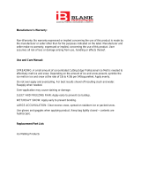
Front View
Side View
2–7/8"
(72 mm)
1/2" Knock-out
(x 5 back) (x 5 bottom)
Mounting Base
CL
1/2"
(13 mm)
7/8"
(23 mm)
6–5/8"
(170 mm)
7–5/8"
(193 mm)
1–7/8" (49 mm)
1/2"
(14 mm)
3/16" (5 mm)
20
Mod Boiler
19
WiFi Snow Melting Control 670
Boiler & Mixing / Electric
Power 115 V (ac) ±10%, 60 Hz, 20 VA
Relays 230 V (ac) 5 A 1/3 hp
Var. Pump 230 V (ac) 2.4 A
1084-01
Designed and assembled in Canada
Date Code
H2055A
1 kΩ max 1 kΩ max
Opn
3
Var
2
–
Mix V/mA
1
+
Pwr
4
Mix
Cls
5
Blu
8
Yel
9
Brn/
10
Slab
Man
11
Melt
C
12
Blk/
7
Com
Red
6
Boiler 1
21
Stage 1
Boiler 1
Stage 2
Heat
Relay
System
Pump–
22
+
23 24 25
Do Not Apply Power
Mix
15
Sup
Com
16
Boil
17
Out
18
Com
14
tN4
13 282726
Power
29
L
30
N
For product literature:
Pour la documentation du produit:
Para la literatura del producto:
tekmarControls.com
Disconnect all power before opening.
WARNING
Coupez l'alimentation avant l'ouverture.
ATTENTION
Desconecte la electricidad antes de abrir.
ADVERTENCIA
Signal wiring must be rated at least 300 V.
Le câblage du signal doit être d'une capacité d'au moins 300 V.
Cableado de señal debe tener una
calificación mínima de 300 V.
Contains WiFi transceiver:
FCC ID: Z64-CC3100M0DR1, IC: 4511-CC3100M0DR1
Meets Class B: FCC Part 15B, ICES-003
Manual Melt
Time Left
- - : - - hrs
Outdoor
32 °F
Settings Status
System is Melting
Stop
10:30 AM
Warming Up

5 of 48
Installing the Enclosure
• Install the control enclosure to a wall or to an electrical box.
•
Three wiring chamber dividers are included. The dividers provide a barrier to keep low voltage wiring separated from line
voltage wiring.
• If the dividers are not used, then low voltage circuits must use wire rated at least 300 V.
Press down at the fingertip
grips
on top of the front cover
and pull
out and down.
Lift the front cover up and
away
from the control.
Loosen the screws at the
front of the wiring cover.
The wiring cover pulls straight
out from the wiring chamber.
The base is ready for mounting.The control lifts up and away
from the base.
Press the control release clip
on the base inside the wiring
chamber and slide the control
upwards.
Remove the safety dividers
from the wiring chamber by
pulling them straight out of
their grooves.
There are 10 conduit knock-outs at the back
and bottom of the wiring chamber.
13 Mounting holes
Control
release
clip
Control release clip
The control can be mounted on
a standard DIN rail. First remove
the control from its base and then,
using the hooks and spring clip
on the back of the control, mount
it onto the DIN rail. This will be a
popular option for those who prefer
to mount the control inside a larger
electrical panel. The DIN Snap Kit
M9303 is sold separately.
The wiring can enter the
bottom or the back of the
enclosure. Knock-outs pro-
vided in the base allow the
wiring to be run in conduit
up to the enclosure. The
base also has holes that
line up with the mounting
holes of most common
electrical boxes.

6 of 48
Rough-In Wiring
Low-Voltage Wiring
------------------------------------------------------------------------------------- -------------------------------------------------------------------------------------
Pull two conductor 18 AWG LVT cable, up to 500 feet
(150 m) long, for the following equipment:
• Outdoor temperature sensor
• Mix supply sensor
• Boiler sensor
• Single-stage on/off boiler
• Modulating boiler 0-10 V (dc) or 4-20 mA
•
Mixing valve or mixing injection pump using a 0-10 V (dc)
or 4-20 mA signal.
Pull three conductor 18 AWG LVT cable, up to 500 feet
(150 m) long, for the following equipment:
• Mixing valves using a floating action signal
Pull four conductor 18 AWG LVT cable, up to 500 feet
(150 m) long, for the following equipment:
• Snow Sensor 095
• Two-stage on/off boiler
Pull the Snow/Ice Sensor 090 or 094 cable to the control.
Line-Voltage Wiring
------------------------------------------------------------------------------------ ------------------------------------------------------------------------------------
Pull two conductor 14 AWG cable, up to 500 feet
(150 m) long, for the following equipment:
• System pump
• Boiler pump
• Heat exchanger on/off injection pump
• Variable speed injection pump
To prevent the risk of personal injury and/or death, make sure power is not applied to the control until it is fully
installed and ready for final testing. All work must be done with power to the circuit being worked on turned off.
Please be aware local codes may require this control to be installed or connected by an electrician.
•
Install the supplied wiring compartment barriers by sliding them into the grooves provided to isolate the low and line-
voltage wiring.
• Strip all wiring to a length of 3/8 in. or 10 mm for all terminals.
• A circuit breaker or power disconnect that provides power to the control should be located nearby and clearly labeled.
• Refer to the current and voltage ratings at the back of this manual before connecting devices to this control.

7 of 48
• The temperature sensor (thermistor) is built into the sensor
enclosure.
• The outdoor sensor can either be mounted directly onto a
wall and the wiring should enter through the back or bottom
of the enclosure. Do not mount the outdoor sensor with the
conduit knockout facing upwards because rain could enter
the enclosure and damage the sensor.
•
In order to prevent heat transmitted through the wall from
affecting the sensor reading, it may be necessary to install
an insulating barrier behind the enclosure.
•
The outdoor sensor should be mounted on a north-facing
wall. The outdoor sensor should not be exposed to heat
sources such as ventilation or window openings.
•
The outdoor sensor should be installed at an elevation above the
ground that will prevent accidental damage or tampering.
Mounting the Outdoor Sensor
-------------------------------------------------------------------------- --------------------------------------------------------------------------
•
Connect 18 AWG or similar wire to the two terminals provided
in the enclosure and run the wires from the outdoor sensor
to the control. Do not run the wires parallel to telephone or
power cables. If the sensor wires are located in an area
with strong sources of electromagnetic interference (EMI),
shielded cable or twisted pair should be used or the wires
can be run in a grounded metal conduit. If using shielded
cable, the shield wire should be connected to the Com ter-
minal on the control and not to earth ground.
•
Follow the sensor testing instructions in this manual and
connect the wires to the control.
• Replace the front cover of the sensor enclosure.
Wiring the Outdoor Sensor
----------------------------------------------------------------------------- -----------------------------------------------------------------------------
Remove
cover by
sliding up-
wards away
from the
base.
To wire from
the back,
remove the
knock-out in
the sensor
base.
S1
S1
If using
conduit,
remove the
flexible plug
from the
base bottom.
S1
S1
Attach the
base to the
wall, soffit
or electrical
box.
S1
S1
Wires from outdoor
sensor to control’s
outdoor sensor and
sensor common
terminals
Sensor is built into
the enclosure
Wires from
outdoor sensor
and sensor
common
terminals on
tekmar control
S1
S1
Sensor Wiring
At the control:
• Connect the outdoor sensor to terminals 16 and 18.
Com
16
Boil
17
Out
18

8 of 48
The Universal Sensor 082 is designed to mount on a pipe or in a temperature
immersion well. The sensor should be placed downstream of a pump or after
an elbow or similar fitting. This is especially important if large-diameter pipes
are used as the thermal stratification within the pipe can result in erroneous
sensor readings. Proper sensor location requires that the fluid is thoroughly
mixed within the pipe before it reaches the sensor.
Strapped to Pipe
The Universal Sensor can be strapped directly to the pipe using the cable tie
provided. Insulation should be placed around the sensor to reduce the effect
of air currents on the sensor measurement.
Mounting the Boiler and System Sensors
-------------------------------------------------------------- --------------------------------------------------------------
Mounting the Mix Supply Sensor
----------------------------------------------------------------------- -----------------------------------------------------------------------
The mix supply sensor is used when operating a mixing valve or a variable
speed injection pump is installed.
• If applicable, connect the mix supply sensor to terminals 14 and 15.
Mounting the Boiler Sensor
---------------------------------------------------------------------------- ----------------------------------------------------------------------------
The boiler sensor is used when operating a boiler.
• If applicable, connect the boiler sensor to terminals 16 and 17.
Bottom of
Enclosure 080
Universal
Sensor
Cable Tie
Sensor Well
Retaining
Clip
Universal
Sensor
Immersion Well
If a Universal Sensor is mounted onto 1" (25 mm) diameter L type copper pipe,
there is approximately an 8 second delay between a sudden change in water
temperature and the time the sensor measures the temperature change. This
delay increases considerably when mild steel (black iron) pipe is used. In general,
it is recommended that a temperature well be used for steel pipe of diameter
greater than 1-1/4" (32 mm). Temperature wells are also recommended when
large diameter pipes are used and fluid stratification is present.
Conduit Connection
The Universal Sensor and Universal Sensor Enclosure 080 (sold separately) are
specifically designed to mount onto a 3/8" (10 mm) ID temperature well that is
supplied with an end groove. To install the well, plumb a tee into the pipe and fix
the well into the tee. The 080 enclosure has a 7/8" (22 mm) back knockout that
must be removed and fitted over the temperature well. The universal sensor is
then inserted into the well and the retaining clip supplied with the enclosure is
snapped onto the well end groove. If the well has a threaded end, the installer
must supply a standard threaded conduit retaining ring. The two wires from the
sensor are connected to the terminal block provided in the enclosure. The other
side of the terminal block is used to connect wires from the control.
Com
16
Boil
17
Mix
15
Sup
Com
14

9 of 48
Snow/Ice Sensor
--------------------------------------------------------------------------------------- ---------------------------------------------------------------------------------------
Snow Sensor
------------------------------------------------------------------------------------------- -------------------------------------------------------------------------------------------
Slab Sensor
-------------------------------------------------------------------------------------------- --------------------------------------------------------------------------------------------
A Snow/Ice Sensor 090 or 094 can be connected to the control. The 090 has
a 65' (20 m) cable and the 094 has a 208' (63 m) cable. The cable may be
extended to a total length of 500' (150 m) using 18 AWG cable. Any junction
boxes must kept dry.
If the Snow/Ice Sensor input is used:
• Connect the red wire to terminal 6.
• Connect the black wire to terminal 7.
• Connect the blue wire to terminal 8.
• Connect the yellow wire to terminal 9.
• Connect the brown wire to terminal 10.
A Snow Sensor 095 can be connected to the control.
If the Snow Sensor input is used:
• Connect the red wire to terminal 6.
• Connect the black wire to terminal 7.
• Connect the blue wire to terminal 8.
• Connect the yellow wire to terminal 9.
A Slab Sensor 072 or 073 can be installed either alone or together with a Snow
Sensor 095.
If the Slab Sensor input is used:
Connect the slab sensor to terminals 7 and 10.
tekmarNet
The 670 can be connected to other tekmarNet communication compatible controls
using the tN4 bus.
If tekmarNet is used:
•
Connect tN4 on the 670 terminal 11 to the tN4 wiring terminal on the other device.
• Connect C on the 670 terminal 12 to the C wiring terminal on the other device.
• tekmarNet is polarity sensitive.
Blu
8
Yel
9
Brn/
10
Slab
Blk/
7
Com
Red
6
Snow
Sensor
095
Blu
8
Yel
9
Brn/
10
Slab
Blk/
7
Com
Red
6
Blu
8
Yel
9
Brn/
10
Slab
Blk/
7
Com
Red
6
other tN4
control
670
11
C
12
tN4
C
tN4

10 of 48
Equipment Wiring
Wiring the Analog Mixing Output
----------------------------------------------------------------------- -----------------------------------------------------------------------
The control can operate a mixing valve by providing a 0-10 V (dc) or a 4-20
mA signal to the valve actuating motor.
• If applicable, connect the mixing actuator positive (+) to terminal 1.
• If applicable, connect the mixing actuator negative (-) to terminal 2.
The control provides a floating action signal to operate a floating action actuator. The
floating action mixing output uses dry relay contacts that can switch either 24, 120, or
230 V (ac). When using 24 V (ac), a Transformer 009 is required to power the actuator.
The actuator terminals are typically labeled for clockwise and counterclockwise rotation.
The control's open and close terminals are wired to the actuator depending on the
direction the valve rotates to open and close respectively.
• Connect the power source to the Pwr terminal 4 on the control.
• Connect the Opn terminal 3 to the actuator terminal that rotates the valve open.
• Connect the Cls terminal 5 to the actuator terminal that rotates the valve close.
• If using a 24 V (ac) transformer, connect the actuator common to the transformer C.
• If using a 120 V or 230 V (ac) power supply, connect the actuator common to the
power supply neutral (N).
Wiring the Floating Action Mixing Output
--------------------------------------------------------------- ---------------------------------------------------------------
A variable speed injection mixing pump requiring up to 230 V (ac), 2.4 A is
operated through terminals 3 and 4. For simplicity in wiring and troubleshooting,
a separate breaker for the pump is recommended.
• Connect 115 or 230 V (ac) power L to the Pwr Mix terminal 4.
• Connect a wire from Var terminal 3 to the pump L.
• Connect a wire from the pump N to the power Neutral.
• Connect the ground wire (G) to the pump.
Wiring the Injection Mixing Pump
---------------------------------------------------------------------- ----------------------------------------------------------------------
Manual Melt Input
The manual melt input allows the control to be manually switched to melting
operation using a switch. This connection is optional.
If the Manual Melt input is used:
Connect a switch to terminals 13 and 14. The switch may be either dry (no voltage)
or a voltage signal up to 32 V (ac).
Man
Melt
Com
1413
2
–
Mix V/mA
1
+
Com
Close
Open
C
N
L
R
Opn
3
Var
Pwr
4
Mix
Cls
5
L
N
G
L
NG
Opn
3
Var
Pwr
4
Mix

11 of 48
The control provides either a 4-20 mA or a 0-10 V (dc) output to the boiler. Polarity must be
observed.
• Connect the Mod + terminal from the boiler to terminal 19.
• Connect the Mod - terminal from the boiler to terminal 20.
• Some modulating boilers require an enable to start firing the boiler. Connect the boiler enable to
the stage 1 terminals 21 and 22.
The 4 to 20 mA output can be converted to a 0 - 135 Ω output
for a Modutrol IV™ gas valve actuating motor using a 0 - 135 Ω
tekmar Converter 005 (sold separately).
The 4 to 20 mA output can be converted to a 0 - 135 Ω output
for a V9055™ gas valve actuating motor using a 0 - 135 Ω
tekmar Converter 005 (sold separately).
Modutrol IV
tekmar
B
R
W
+
-
tekmar
V9055
+
-
B
R
W
Modutrol IV™
0 - 135 Ω
Actuating
Motor
B
R
W
Mod
+
-
Snow
Melting
Control
670
Modutrol IV™ and V9055™ are trademarks of Honeywell, Inc.
Wiring to a Modulating Boiler
--------------------------------------------------------------------------- ---------------------------------------------------------------------------
Modutrol IV
tekmar
B
R
W
+
-
tekmar
V9055
+
-
B
R
W
B
R
W
V9055™
0 - 135
Ω
Actuating
Motor
Mod
+
-
Snow
Melting
Control
670
Wiring to a Single-Stage Boiler
------------------------------------------------------------------------- -------------------------------------------------------------------------
A single-stage boiler is enabled through the T-T contacts.
• Connect Stage 1 terminals 21 and 22 to the boiler T-T contacts.
Wiring to a Two-Stage Boiler
--------------------------------------------------------------------------- ---------------------------------------------------------------------------
A two-stage boiler is enabled through the T-T contacts.
• Connect Stage 1 terminals 21 and 22 to the boiler's stage 1 contacts.
• Connect Stage 2 terminals 23 and 24 to the boiler's stage 2 contacts.
Stage 1
TT
Boiler 1
21
Stage 1
22
Mod Enable
TT+
-
20
Mod Boiler
19
Boiler 1
21
Stage 1–
22
+
Stage 2
TT
Stage 1
TT
Boiler 1
21
Stage 1
Boiler 1
Stage 2
22 23 24
Modutrol IV V9055

12 of 48
WR
Provide a 15 A circuit for the input power.
• Connect the 115 V (ac) line wire (L) to terminal 29.
• Connect the neutral wire (N) to terminal 30.
N
L
Power
29
L
30
N
Wiring the Input Power
--------------------------------------------------------------------------------- ---------------------------------------------------------------------------------
If the heat relay is operating a pump:
The pump can be rated up to 230 V (ac), 5 A, 1/3 hp and switched through
terminals 25 and 26. For simplicity in wiring and troubleshooting, a separate
breaker for each pump is recommended.
• Connect the power source line wire (L) to terminal 26.
• Connect a wire from terminal 25 to the pump L.
• Connect a wire from the pump N back to the power source neutral.
• Connect the ground wire (G) to the pump.
If the heat relay is wired to an electrical contactor:
• Connect a wire from terminal 25 to the electrical contactor R.
• Connect a wire from terminal 26 to the electrical contactor C.
If the heat relay is wired to a 24 V(ac) on-off valve:
• Connect the power source red wire (R) to terminal 25.
• Connect a wire from terminal 26 to the valve R.
• Connect a wire from the valve C to the power source common.
Wiring the Heat Relay
---------------------------------------------------------------------------------- ----------------------------------------------------------------------------------
A system pump requiring up to
230 V (ac), 5 A, 1/3 hp
can be switched through
terminals 27 and 28. For simplicity in wiring and troubleshooting, a separate
breaker for each pump is recommended.
• Connect the power source line wire (L) to terminal 28.
• Connect a wire from terminal 27 to the pump L.
• Connect a wire from the pump N back to the power source neutral.
• Connect the ground wire (G) to the pump.
Wiring the System Pump
------------------------------------------------------------------------------- -------------------------------------------------------------------------------
L
N
G
L
NG
Heat
Relay
25
26
R
C
RC
Heat
Relay
25
26
Heat
Relay
25
26
L
N
G
L
NG
System
Pump
2827

13 of 48
A good quality test meter capable of measuring up to 5,000 kΩ
(1 kΩ = 1000 Ω) is required to measure the sensor resistance.
In addition, the actual temperature must be measured with
either a high-quality digital thermometer, or if a thermometer
is not available, a second sensor can be placed alongside
the one to be tested and the readings compared.
First, measure the temperature using the thermometer and
then measure the resistance of the sensor at the control. The
wires from the sensor must not be connected to the control
while the test is performed. Using the chart below, estimate
the temperature measured by the sensor. The sensor and
thermometer readings should be close. If the test meter reads
a very high resistance, there may be a broken wire, a poor
wiring connection or a defective sensor. If the resistance is
very low, the wiring may be shorted, there may be moisture
in the sensor or the sensor may be defective. To test for
a defective sensor, measure the resistance directly at the
sensor location.
Do not apply voltage to a sensor at any time as damage
to the sensor may result.
Testing the Sensor Wiring
Temperature Resistance Temperature Resistance Temperature Resistance Temperature Resistance
°F °C °F °C °F °C °F °C
-50 -46 490,813 20 -7 46,218 90 32 7,334 160 71 1,689
-45 -43 405,710 25 -4 39,913 95 35 6,532 165 74 1,538
-40 -40 336,606 30 -1 34,558 100 38 5,828 170 77 1,403
-35 -37 280,279 35 2 29,996 105 41 5,210 175 79 1,281
-30 -34 234,19 6 40 4 26,099 110 43 4,665 180 82 1,172
-25 -32 196,358 45 7 22,763 115 46 4,184 185 85 1,073
-20 -29 165,180 50 10 19,900 120 49 3,760 190 88 983
-15 -26 139,403 55 13 17,436 125 52 3,383 195 91 903
-10 -23 118,018 60 16 15,311 130 54 3,050 200 93 829
-5 -21 100,221 65 18 13,474 135 57 2,754 205 96 763
0 -18 85,362 70 21 11,883 140 60 2,490 210 99 703
5 -15 72,918 75 24 10,501 145 63 2,255 215 102 648
10 -12 62,465 80 27 9,299 150 66 2,045 220 104 598
15 -9 53,658 85 29 8,250 155 68 1,857 225 107 553
Testing the Control Wiring
Remove the front cover from the control.
Testing the Power
------------------------------- -------------------------------
• Use an electrical meter set to measure (ac) voltage.
• Measure between the L and N terminals.
• The reading should be 115 V (ac) +/– 10%.
Hand Manual Override
--------------------------- ---------------------------
The control includes a Hand Manual Override menu to check
if the control’s relays are operating and that the control is wired
correctly to the snow melting equipment.
Step 1:
Press Settings button.
Step 2:
Press Override button.
Step 3:
Press Manual Override.
Step 4:
Select Manual Override to Hand.
Step 5:
Press Back button.
Step 6:
The following outputs can be operated:
• System Pump relay
• Heat Relay
• Boiler Stage 1 relay
• Boiler Stage 2 relay
• Boiler Modulation 0-10 V (dc) or 4-20 mA signal
• Mix System Output 0-10 V (dc) or 4-20 mA signal
• Mix System Output floating action relays
• Mix System Output variable-speed injection pump
For each relay output
• Use an electrical meter set to measure (ac) voltage.
• Measure between the relay wiring terminals.
• When the relay is off, the voltage should be 115 V (ac).
• When the relay is on, the voltage should be 0 V (ac).
For the Boiler Modulation
• Use an electrical meter set to measure V (dc) or mA.
• Set the Boiler Modulation to 100%.
•
The voltage between the + and – wiring terminals should be
10 V (dc) or 20 mA.
• Set the Boiler Modulation to 0%.
•
The voltage between the + and – wiring terminals should be
0 V (dc) or 4 mA.
For the Mix System Output – Floating Action
• Use an electrical meter set to measure (ac) voltage.
• Set the Mix Output to 100%. The floating action open wiring
terminal will be closed for the length of the motor speed set-
ting (default is 105 seconds).
• When opening, the voltage between the open and common
wiring terminals should be 24 V (ac) or 115 V (ac).
•
When opening, the voltage between the close and common
wiring terminals should be 0 V (ac).
• Set the Mix Output to 0%. The floating action closed wiring
terminal will be closed for the length of the motor speed set-
ting (default is 105 seconds).
•
When closing, the voltage between the open and common
wiring terminals should be 0 V (ac).
• When closing, the voltage between the close and common
wiring terminals should be 24 V (ac) or 115 V (ac).

14 of 48
Manual Override – Maximum Heat
In hydronic application modes, the control includes a
Maximum Heat operation where the control operates the
snow melting system to maintain the maximum allowed
heating setpoints. This allows testing of the snow melting
system during warm weather.
Step 1:
Press Settings button.
Step 2:
Press Override button.
Step 3:
Press Manual Override.
Step 4:
Select Manual Override to Max Heat.
Step 5:
Press Back button. The control starts the Max Heat
operation.
Step 6:
Exit the Manual Override by selecting Auto.
When operating a hydronic snow melting system, it is necessary
to purge and bleed all air out of the system. The control includes
a Purge operation where the system, primary and boiler pumps
are all turned on to assist in purging air from the system.
Step 1:
Press Settings button.
Step 2:
Press Override button.
Step 3:
Press Manual Override.
Step 4:
Select Manual Override to Purge.
Step 5:
Press Back button. The control starts the Purge
operation.
Step 6:
Exit the Manual Override by selecting Auto.
Manual Override – Purge
The snow melting system can be manually turned off and the
control remains off until manually changed back to Auto. This
allows the installer or end user to permanently disable the snow
melting system without removing power from the control.
Step 1:
Press Settings button.
Step 2:
Press Override button.
Step 3:
Press Manual Override.
Step 4:
Select Manual Override to Off.
Step 5:
Press Back button. The control is now in the off manual
override.
Step 6:
Exit the Manual Override by selecting Auto.
Manual Override – Off
When operating an electric snow melting system, the control
includes a Test operation where the electrical heating cables
can be energized for 10 minutes, after which the control
resumes normal operation. This allows testing of the electric
snow melting system during warm weather.
Step 1:
Press Settings button.
Step 2:
Press Override button.
Step 3:
Press Manual Override.
Step 4:
Select Manual Override to Test.
Step 5:
Press Back button. The control starts the electric
test operation for up to 10 minutes before exiting
automatically.
Step 6:
Exit the Manual Override by selecting Auto.
Manual Override – Test
For the Mix Output – Analog Mixing
• Use an electrical meter set to measure V (dc) or mA.
• Set the Mix Output to 100%.
•
The voltage between the + and – wiring terminals should be
10 V (dc) or 20 mA.
• Set the Mix Output to 0%.
•
The voltage between the + and – wiring terminals should be
0 V (dc) or 4 mA.
For the Mix Output – Variable Speed Injection Mixing
• Use an electrical meter set to measure V (ac).
• Set the Mix Output to 100%.
• The voltage between the Var and N wiring terminals should
be 115 V (ac).
• Set the Mix Output to 0%.
• The voltage between the Var and N wiring terminals should
be 0 V (ac).
Exiting the Hand Manual Override
--------------- ---------------
• Exit the Manual Override by selecting Auto.
• Install the front cover.
Access Levels
The control is shipped pre-programmed with common settings.
The control has an
“
Installer
”
access level that allows full
access to all settings and a
“
User
”
access level that restricts
the number of settings available. The control defaults to the
“
User
”
access level after 12 hours of operation.
To change to the
“
Installer
”
access level:
• Step 1: Press the Settings button.
• Step 2: Press the Toolbox button.
• Step 3: Press Access Level.
• Step 4: Press the Installer radio button.

15 of 48
Home Screen
User Interface
System Operation
View status of sensor
readings and equipment.
Remaining melting
run time
System operation
information
Go to settings menu
to setup control
Information about slab
and outdoor conditions
SYSTEM IS MELTING
•
The control has either detected snow/ice and automatically started or the control was manually
started.
• "Warming Up" is shown when the slab is below the slab target temperature.
SYSTEM IS OFF
• The snow melting system is off and is ready to detect snow or ice.
•
"Warm Weather Shut Down" is shown when the slab and outdoor temperature are above the
WWSD setting. During WWSD, the snow will melt naturally due to warm outdoor temperatures.
• "Cold Weather Shut Down" is shown when the outdoor temperature is below the CWCO setpoint.
The outdoor temperature is so cold the heating system does not have capacity to melt snow.
•
"Melt Pending" is shown when the system is off during CWCO but will resume melting once the
outdoor temperature increases above the CWCO setpoint.
SYSTEM IS IDLING
• The control is pre-heating the slab to the idling setpoint. This reduces the amount of time needed
to reach the melting setpoint in the event snow or ice is detected.
STORM PREDICTED
•
The Internet weather forecast is predicting a snow fall and the control is pre-heating the slab to
the storm setpoint. This reduces the amount of time needed to reach the melting setpoint in the
event snow or ice is detected.
SYSTEM IN OVERRIDE / SYSTEM IN EXERCISING
• The control is in a manual override for testing, commissioning or exercising.
• The description field explains which type of override is active.

16 of 48
Symbols
!
WARNING SYMBOL
The control has a error message. Press the warning symbol to determine the error code and information on how
to take corrective action. Refer to the Troubleshooting section for a list of error codes.
Help Screen
The display includes a Help screen for each setting. The Help screen provides a description of the setting that is identical to
the description found in the Installation and Operation Manual.
Status Menu Navigation
Step 1: Press the Status button on the Home Screen.
Step 2: Press either the System, Slab or Weather button.
Step 3: Press up or down buttons to scroll through the list.

17 of 48
System Status Menu
Description Range Access
MANUAL MELT INPUT
When Manual Melt wiring terminal 13 is shorted to common wiring terminal 14, the control is enabled
and enters the melting operation unless prevented by warm weather shut down or cold weather
cut out. When the manual melt input is disconnected, the control completes the melting cycle and
then returns to off, idle or storm operation.
Conditions: Always
Off, Enabled
User
Installer
TEKMARNET
When tekmarNet communication is present, the status shows active. When there is no tekmarNet
communication, the status is off.
Conditions: Always
Off, Active
User
Installer
BOILER TARGET
The boiler target calculated by the control based on outdoor temperature, slab temperature and the
melting, idling, or storm setpoints. “- - -” is displayed when no heat is required.
Conditions: Application mode is set to Boiler or Boiler+Mix.
– – –,
50 to 230°F
(10.0 to 110.0°C)
User
Installer
BOILER SUPPLY
Current boiler supply water temperature.
Conditions: Application mode is set to Boiler or Boiler+Mix.
-31 to 266°F
(-35.0 to 130.0°C)
Installer
BOILER OUTPUT
Current boiler plant percent output.
Conditions: Application mode is set to Boiler or Boiler+Mix.
0 to 100%
User
Installer
STAGE 1
Current status of the stage 1 relay.
Conditions: Application mode is set to PWM Zone, Mixing, Boiler, or Boiler+Mix.
On or Off
User
Installer
STAGE 2
Current status of the stage 2 relay.
Conditions:
Boiler type is set to Stage 2.
On or Off
User
Installer
MIX TARGET
The mix target calculated by the control based on outdoor temperature, slab temperature
and one of either the melting, idling, or storm setpoints. ”- - -” is displayed when no heat is
required.
Conditions: Application mode is set to Mixing or Boiler+Mix.
– – –,
70 to 200°F
(21.0 to 93.5°C)
User
Installer
MIX SUPPLY
Current mix supply water temperature.
Conditions: Application mode is not set to Electric.
-31 to 266°F
(-35.0 to 130.0°C)
User
Installer
MIX OUTPUT
Current position of the mixing valve or output of the variable speed injection pump.
Conditions: Application mode is set to Mixing or Boiler+Mix.
0 to 100%
User
Installer
SYSTEM PUMP
Current status of the system loop pump.
Conditions: Application mode is set to PWM Zone, Mixing, Boiler or Boiler+Mix.
On or Off
User
Installer
HEAT RELAY
Current status of the heat relay.
Conditions: Application mode is set to Electric, PWM Zone, Mixing.
On or Off
User
Installer
ELECTRIC ENABLE RELAY
Current status of the electric snow melt enable relay.
Conditions: Application mode is set to Electric.
On or Off
User
Installer

18 of 48
Slab Status Screen
Weather Status Screen
Description Range Access
OUTDOOR
Current outdoor air temperature as measured by the outdoor sensor or from the tekmarNet
system or Internet weather forecast. “– – –” is displayed when no outdoor temperature reading
is available.
Conditions: Always available.
– – –,
-67 to 149°F
(-55.0 to 65.0°C)
User
Installer
SLAB TARGET
The slab target calculated by the control based on outdoor temperature and the melting,
idling, or storm setpoints. “- - -” is displayed when no heat is required.
Conditions: Always available.
– – –,
32 to 110°F
(0 to 43.0°C)
Installer
SLAB SENSOR
Current slab sensor temperature.
Conditions:
Snow/ice sensor set to In-slab or slab sensor is set to On.
-58 to 167°F
(-50.0 to 75.0°C)
User
Installer
SENSOR WATER STATUS
Current status of snow/ice sensor moisture detector.
Conditions:
Snow/ice sensor is set to In-slab or Aerial.
DRY or WET
User
Installer
Current outdoor conditions
Predicted snow forecast
When WiFi is turned on, the control receives weather data from the Internet. The current weather, outdoor temperature and
forecast snow fall information is displayed.

19 of 48
Settings Menu Navigation
Step 1: Press the Settings button on the Home Screen.
Step 2: Press one of the ten buttons.
Step 3: Press up or down buttons to scroll through the list.
Step 4: Press the highlighted setting name to change the setting value.

20 of 48
Description Range Access
MELTING SETPOINT
Select the desired temperature of the snow melt surface when melting.
Conditions: Always available.
32 to 95°F
(0.0 to 35.0°C)
Default = 36°F
(2.0°C)
User
Installer
IDLING SETPOINT
Select the desired temperature of the snow melt surface when idling. Idling preheats the slab
when the slab is dry but cold and allows faster reaction time to reach the melting temperature
when snow is detected. Recommended for commercial use only.
Conditions: Always available.
OFF, 20 to 95°F
(-6.5 to 35.0°C)
Default = Off
User
Installer
STORM SETPOINT
Select the desired temperature of the snow melt surface while operating in the storm
operation. Storm operation temporarily preheats the slab to allow faster reaction time to
reach the melting temperature when snow is detected. Storm operation is automatically
activated by the Internet weather forecast or manually started by a User Switch or Gateway.
Conditions: Always available.
OFF, 20 to 95°F
(-6.5 to 35.0°C)
Default = Off
User
Installer
MANUAL MELT TIME
Select the amount of running time when manually starting the system.
Conditions: Always available.
0:30 to 24:00
hours
Default = 4:00
hours
User
Installer
ADD MELT TIME
Select the amount of additional melting time after the Snow/Ice Sensor is dry. This allows
low spots on the slab to fully dry before the snow melting system is shut off.
Conditions: Snow/ice sensor is set to In-slab.
0:00 to 6:00
hours
Default = 0:00
hours
Installer
STORM RUN TIME
Select the amount of storm run time to pre-heat the slab when advised of a winter storm
warning.
Conditions:
Storm setpoint is set to a temperature.
0:30 to 24:00
hours
Default = 8:00
hours
Installer
SENSITIVITY
Select how sensitive Snow/Ice Sensor is to water detection.
Conditions: Snow/ice sensor is set to In-slab or Aerial.
Auto, Min, -2, -1,
Mid, +1, +2, Max
Default = Auto
Installer
WWSD
Select the temperature above which the snow melting system is shut off during warm
weather. This allows the snow or ice to melt off the slab naturally.
Conditions: Always available.
Auto, 32 to 95°F
(0.0 to 35.0°C)
Default = Auto
Installer
CWCO
Select the temperature below which the snow melting system is shut off during extremely
cold weather. Below this temperature, the heat loss of the slab exceeds the capacity of the
boiler or heating appliance.
Conditions: Always available.
Off, -30 to 50°F
(-34.5 to 10.0°C)
Default = 10°F
(-12.0°C)
Installer
Temp Menu
/