Page is loading ...

© 2016 tekmar 665
_
D - 06/16
665
_
D
06/16
Snow Melting
Replaces: 04/12
Snow Detector & Melting Control 665
Installation & Operation Manual
The Snow Detector & Melting Control 665 is a microprocessor-based control which operates a single zone snow melting system.
The control can operate automatically when a Snow / Ice Sensor 090 is installed or the user can manually enable and/or disable the
system. When the control is in the melting mode, the slab is maintained at a “Melting” temperature through an on/off output which
operates a contactor for electrical cables, a boiler, an injection pump or an injection valve. When the control is not in the melting mode,
the melt system can either be shut down or it can be maintained at an idle temperature for faster response and improved safety. The
665 control includes a large Liquid Crystal Display (LCD) in order to view system status and operating information.
Additional features include:
1
Red
2
Blk
3
Blu
4
Yel
5
Brn/
Slab
6
Out
7
Com
8
tN2
9
Melt/Idle
Demand
10 11
Heat
12 13
Melting
14 15 17
Sys
P1
16
Power
L
N
Test
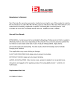
Snow Detector & Melting Control 665
Pulse Width Modulation
Idle Demand
Melt Demand
not testing
testing
testing paused
For maximum heat,
press and hold Test
button for 3 seconds.
off
red
red
Do not apply power
Input
Snow/Ice Sensor
090 installed with
Sensor Socket
091 Optional
Input
Slab Sensor
Optional
Input
Remote Display Module (RDM)
or
Remote Start / Stop Module
or
Input
Outdoor
Sensor
Included
Input
Melt/Idle
Demand
Output
System
Pump
Input
115 V (ac)
Power
Supply
OR
Melt Demand
Idle Demand
WWSD
Water
Melting
Start
Menu Item
Stop
Do not apply power
Output
Boiler
Output
Turn on injection
pump
Output
Turn on relay for
electric cables
Output
Melt Relay
OR
OR
Signal wiring must be rated at least 300 V.
900-03
Designed and assembled in Canada by
tekmar Control Systems Ltd.
Power 115 V ± 10% 50/60 Hz 600 VA
Relays 230 V (ac) 5 A 1/3 hp
Demand 20 to 260 V (ac) 2 VA
Meets Class B:
Canadian ICES
FCC Part 15
H2028D
Date Code
• Slab Outdoor Reset
• Automatic snow detection and melt control (with 090 sensor)
• Temporary Idle
• Manual Override
• Warm Weather Shut Down
• Cold Weather Cut Out
• Remote display and adjustment capabilities
• Test sequence to ensure proper component operation
• Equipment Exercising
• CSA C US certified (approved to applicable UL standards)

2 of 28
© 2016 tekmar 665
_
D - 06/16
Table of Contents
Access Levels .................................................Pg 16
Control Settings ..............................................Pg 17
View Menu ..............................................Pg 17
Adjust Menu ...........................................Pg 18
Monitor Menu .........................................Pg 19
Schedule Menu ......................................Pg 20
Miscellaneous Menu .............................Pg 20
Testing and Troubleshooting ........................Pg 21
Error Messages ......................................Pg 23
Technical Data .................................................Pg 27
Limited Warranty ............................................Pg 28
User Interface ..................................................Pg 2
Description of Display Elements ..................Pg 3
Sequence of Operation ..................................Pg 4
Section A: General Operation ..............Pg 4
Section B: Snow Melting .......................Pg 4
Section C: Melting Enable / Disable ....Pg 6
Section D: Melting Operation ...............Pg 8
Section E: Idling Operation ..................Pg 9
Installation .......................................................Pg 10
Electrical Connections ..........................Pg 12
Testing The Wiring .................................Pg 14
DIP Switch Settings ........................................Pg 16
How to Use the Data Brochure
This brochure is organized into four main sections. They are: 1) Sequence of Operation, 2) Installation, 3) Control Settings, and
4) Troubleshooting. The Sequence of Operation section has 5 sub-sections. We recommend reading Section A: General of the
Sequence of Operation, as this contains important information on the overall operation of the control. Then read to the sub-sections
that apply to your installation.
The Control Settings section (starting at DIP Switch Settings) of this brochure describes the various items that are adjusted and
displayed by the control. The control functions of each adjustable item are described in the Sequence of Operation.
User Interface
The 665 uses a Liquid Crystal Display (LCD) as the method of supplying information. You use the LCD in order to setup and monitor
the operation of your system. The 665 has four push buttons (Menu, Item, (Start), (Stop)) for selecting and adjusting settings. As
you program your control, record your settings in the ADJUST Menu table which is found in the second half of this brochure.
Menu
All of the items displayed by the control are organized into various menus. These menus
are listed on the left hand side of the display (Menu Field). To select a menu, use the
Menu button. By pressing and releasing the Menu button, the display will advance to
the next available menu. Once a menu is selected, there will be a group of items that can
be viewed within the menu.
Item
The abbreviated name of the selected item will be displayed in the item field of the
display. To view the next available item, press and release the Item button. Once you
have reached the last available item in a menu, pressing and releasing the Item button
will return the display to the first item in the selected menu.
Adjust
To make an adjustment to a setting in the control, begin by selecting the appropriate
menu using the Menu button. Then select the desired item using the Item button. Finally,
use the and / or button to make the adjustment.
Additional information can be gained by observing the Status field of the LCD. The status
field will indicate which of the control’s outputs are currently active. Most symbols in the
status field are only visible when the VIEW Menu is selected.
Menu Item
Menu Item
Menu Item

© 2016 tekmar 665
_
D - 06/16
3 of 28
Display
Symbol Description
Pump
Displays when the system pumps are
operating.
Pointer
Displays the control operation as
indicated by the text.
Override
Displays when the control is in override mode.
°F, °C, min, hr, sec
Units of measurement.
Warning
Displays when an error exists or when a limit
has been reached.
Heat
Displays when the Heat relay is
turned on.
Lock / Unlock
Displays when the access levels are locked or
unlocked.
Melt Demand
Idle Demand
WWSD
Water
Melting
Item Field
Displays an abbreviated
name of the selected item
Menu Field
Displa
ys the
curr
ent menu
Status Field
Displa
ys the
curr
ent status
of the control's
inputs, outputs
and operation
Number Field
Displays the current value of the selected it
em
Buttons
Selects Menus, Items
and adjust settings
The following defined terms and symbols are used throughout this manual to bring attention to the presence of hazards of various risk
levels, or to important information concerning the life of the product.
- Warning Symbol: Indicates presence of hazards which can cause severe personal injury, death or
substantial property damage if ignored.
- Double insulated
- Local level, appliances
INSTALLATION
CATEGORY II
Definitions

4 of 28
© 2016 tekmar 665
_
D - 06/16
Section B1: General Snow Melting
WARM WEATHER SHUT DOWN (WWSD)
The control has a warm weather shut down that prevents the control from entering the melt or idle modes in order to conserve energy.
While in WWSD, the word WWSD is displayed in the STATUS item in the VIEW menu and the WWSD pointer is on the display. The
WWSD item in the ADJUST menu can be either set to Automatic or it can be set to a temperature.
Automatic (Auto)
When the WWSD is set to AUTO, the WWSD occurs when the slab temperature and
the outdoor temperature exceed the Melting setting by 2°F (1°C). The control exits the
WWSD when the slab or outdoor temperature falls to the Melting setting temperature.
Adjustable WWSD
When the WWSD is set to a temperature, the WWSD occurs when the outdoor air
temperature exceeds the WWSD setting by 1°F (0.5°C) and when the slab temperature
exceeds 34°F (1°C). The control exits WWSD when the outdoor air temperature falls 1°F
(0.5°C) below the WWSD setting or if the slab temperature falls below 34°F (1°C). This
allows the Melting Temperature setting to be set higher than the WWSD. This is useful
where high slab temperatures are required to melt the snow or ice. A good example of
this is installations using paving bricks on top of sand and concrete layers.
COLD WEATHER CUT OUT (CWCO)
Maintaining the system at either the melting or idling temperature during extremely cold temperatures can be expensive or impossible.
The control turns the snow melting system off when the outdoor air temperature drops below the Cold Weather Cut Out (CWCO)
temperature. While the control is in CWCO, the word CWCO is displayed in the STATUS item in the VIEW menu. The heater in the
sensor is kept on during CWCO until the control detects moisture. If water is detected, the heater is turned off but the control retains
the moisture detected information. When the outdoor temperature rises above the CWCO temperature, the control exits CWCO and
if the Snow / Ice Sensor 090 detected moisture during CWCO, the control initiates Melting mode. If the control has been started prior
to the CWCO, it resumes the Melting mode once the outdoor air temperature rises above the CWCO temperature.
Sequence of Operation
Section A
General
Operation
Page 4
Section B
Snow
Melting
Page 4 - 5
Section C
Melting Enable
/ Disable
Page 6 - 8
Section D
Melting
Operation
Page 8 - 9
Section E
Idling
Operation
Page 9
Section A: General Operation
POWERING UP THE CONTROL
When the Snow Detector & Melting Control 665 is powered up, the control displays all LCD segments for 2 seconds, then the con-
trol type number in the LCD for 2 seconds. Next, the software version is displayed for 2 seconds. Finally, the control enters into the
normal operating mode and the LCD defaults to displaying the current outdoor air temperature.
EXERCISING (EXERCISE)
The 665 has a built-in pump exercising function. The exercising period is adjustable and is factory set at 70 hours. If a pump output
has not been operated at least once during every exercising period, the control turns on the output for 10 seconds. This minimizes
the possibility of a pump or valve seizing during a long period of inactivity.
Note: The exercising function does not work if power to the control or pumps is disconnected.
Section B: Snow Melting
Section B1
General
Snow Melting
Outdoor
Temperature
Slab
Temperature
MELT
IDLE
WWSD
CWCO
Control enters
Idle and waits
for Melt Enable

© 2016 tekmar 665
_
D - 06/16
5 of 28
RUNNING TIME (RUN TIME)
The running time is the length of time that the system operates once it has reached its slab target temperature. During the time that
the system is approaching its slab target temperature, the RUN TIME does not decrease. Once the system reaches its slab target
temperature, the RUN TIME begins counting down. When the RUN TIME reaches 0:00 as displayed in the Status item in the VIEW
menu, the system has finished melting.
Note: The running time is only applicable when a manual melting enable signal starts the snow melting system. Refer to Section C1 for
a description of a manual melting enable.
STATUS (STATUS)
While in the VIEW menu there are a number of items available to determine the current status of the system. To view the current
status of the system, select the STATUS item in the VIEW menu.
• STRT The word STRT is displayed after the snow melting system has been manually enabled. It is displayed until the
zone reaches its slab target temperature. If the zone is at its slab target temperature, STRT is displayed for five
seconds after the snow melting system has started operation. This is to verify that the control has entered into the
Melting mode.
• STOP The word STOP is displayed for five seconds after the snow melting system has been manually disabled. The
word STOP is also displayed if either a Remote Start / Stop Module 039, Remote Display Module 040 or the Stop
on the control stops the snow melting system and an external melt demand is still present.
• IDLE The word IDLE is displayed as long as the zone is operating at its idling temperature.
•
“IDLE” The word IDLE is flashed on the display as long as the zone is operating in temporary idle.
• EXT The word EXT is displayed when the RUN TIME has reached 0:00 and the control still has an external melt demand.
In this situation, the zone continues melting until the melt demand is removed or the control is stopped.
• DET The word DET is displayed after the snow melting system has been automatically enabled by the
Snow / Ice Sensor 090 and the zone is at its slab target temperature. DET is also displayed once the control is
manually enabled after automatic detection by the 090 and the running time has counted down to 0:00.
• 0:00 to 23:59 hr While the zone is up to temperature and melting, the remaining RUN TIME is displayed.
• INF If an infinite RUN TIME is selected and the zone is melting, INF is displayed.
• WWSD When the zone is in Warm Weather Shut Down, WWSD is displayed.
• CWCO When the control is in Cold Weather Cut Out, CWCO is displayed.
Cycle (20 minutes)
Relay On Time Relay Off Time
Relay On Time Relay Off Time
Relay On Time
Less Heat
More Heat
SNOW MELTING OVERRIDE
If the AWAY setting is selected in the SCHEDULE menu, the snow melting system is shut
down. Both the Melting and Idling temperatures are ignored as long as the control remains
in the Away mode.
SYSTEM PUMP OPERATION (SYS P1)
The system pump (Sys P1) contact closes and remains closed as long as the system is either in the Melting or Idling mode. The
system pump contact shuts off if the control is in CWCO, WWSD, or if there is no call for Melting or Idling.
HEAT CONTACT OPERATION
The control uses the Heat contact to control the temperature of the slab.
When the control is either Melting or Idling, the Heat contact operates
on a 20 minute cycle. If the slab requires more heat, the on time in each
cycle is increased. If the slab requires less heat, the on time of each
cycle is decreased. The Heat contact shuts off if the control is in Cold
Weather Cut Out (CWCO), Warm Weather Shut Down (WWSD), or if
there is no call for Melting or Idling.
MELTING CONTACT OPERATION
The Melting contact (terminals 13 and 14) closes and remains closed as long as the system is in the melting mode. This contact
can be used as an external signal to indicate that the system is currently in the melting mode. This contact can also be used as a
means of prioritizing or enabling multiple snow melting controls.
PURGE
The system pump (Sys P1) and zoning device continue to operate for 20 seconds after the last demand is removed. This purges
the residual heat from the boiler(s) into the snow melting slab.

6 of 28
© 2016 tekmar 665
_
D - 06/16
Section C: Melting Enable / Disable
Section C1
Snow Melting
Enable
Section C2
Snow Melting
Disable
Section C1: Snow Melting Enable
The snow melting system can be enabled manually or automatically. A melting enable signal applied to the control places the system
into the melting mode. If a melting enable signal is applied once the system is already in the melting mode, the control responds to
the last command received.
MANUAL MELTING ENABLE
A manual melting enable signal requires the user to manually start the snow melting system and can be provided from the Start
button on the control, Remote Start / Stop Module 039, Remote Display Module 040, or an external melt demand.
7
9
8
Start / Stop
StopStart
Start Button on the Control
The snow melting system is enabled by pressing the Start button on the control while
in the VIEW menu. The control then displays the RUN TIME setting to allow the user to
adjust it. Once the snow melting system is enabled, the word STRT is displayed for at
least 5 seconds in the STATUS item while in the VIEW menu. If the Start button on the
control is pressed while the system is already melting and up to temperature, the running
time counter is reset to the RUN TIME setting.
Remote Start / Stop Module 039
The snow melting system is enabled by pressing the button on the front of the 039. While
the zone is coming up to temperature, a green indicator light flashes on the front of the
039. Once the zone is up to temperature and the RUN TIME is counting down, the green
indicator light on the front of the 039 is on solid.
Remote Display Module 040
The snow melting system is enabled by pressing the up button on the 040 while in
the VIEW menu. The 040 then displays the RUN TIME setting to allow the user to
adjust it. Once the snow melting system is enabled, the word STRT is displayed for at
least 5 seconds in the STATUS item while in the VIEW menu.

© 2016 tekmar 665
_
D - 06/16
7 of 28
External Melt Demand (DIP switch set to Melt Demand)
The snow melting system is enabled when a voltage between 24 and 240 V (ac) is applied
across the Melt/Idle Demand terminals (9 and 10). An external melt demand must be
present for at least 4 seconds in order to start the snow melting system. If the RUN TIME
reaches 0:00 and the external melt demand is still present, the control continues melting
until the external melt demand is removed or the system is otherwise stopped.
Note: This operation only occurs if the Idle Demand / Melt Demand DIP switch is set to
the Melt Demand position.
AUTOMATIC MELTING ENABLE (Snow / Ice Sensor 090)
The 665 uses the Snow / Ice Sensor 090 to provide an automatic melting enable signal to
start the snow melting system. The control continually monitors the 090 for the presence
of moisture. Once moisture is detected, the water pointer is displayed in the LCD and the
snow melting system is enabled.
Water Detection Sensitivity (SENSTVTY)
The 665 has a Sensitivity setting which compensates for varying outdoor conditions which
could affect how the moisture detector in the 090 interprets the presence of moisture.
This adjustable setting is available through the SENSTVTY item in the ADJUST menu of
the control. As snow becomes contaminated with dirt, and as the sensor itself becomes
dirty, the control may incorrectly indicate the presence of water. If this condition occurs,
clean the surface of the sensor and / or turn down the SENSTVTY setting. If the snow in
your area is very clean, the SENSTVTY setting may need to be increased before snow
is detected. If AUTO is selected, the control automatically adjusts the sensitivity level
used to detect moisture.
Section C2: Snow Melting Disable
The snow melting system can be disabled manually or automatically. A melting disable signal applied to the control takes the zone
out of the melting mode. Once the snow melting system is disabled, the zone operates in the idling mode. The idling mode allows the
zone to be operated at either a lower temperature or turned off.
MANUAL MELTING DISABLE
A manual melting disable signal requires the user to manually stop the snow melting system and can be provided from the Stop
button on the control, Remote Start / Stop Module 039, Remote Display Module 040, or an external idle demand.
Stop Button on the Control
The Stop button on the control can be used to stop the snow melting system. The snow melting system is disabled by pressing
the Stop button on the control while in the VIEW menu. Once the snow melting system is disabled, the word STOP is displayed
for 5 seconds in the STATUS item of the appropriate zone while in the VIEW menu.
Remote Start / Stop Module 039
A Remote Start / Stop Module 039 can be used to stop the snow melting system. The snow melting system is disabled by press-
ing the button on the face of the 039. When the system is stopped, a solid Red Indicator Light is displayed on the face of the 039
for five seconds. If the snow melting system is disabled while there is still an external melt demand for snow melting, the 039
displays a solid red indicator light until the external demand is removed.
Remote Display Module 040
A Remote Display Module 040 can be used to stop the snow melting system. The snow melting system is disabled by pressing
the down button on the 040 while in the VIEW menu. Once the snow melting system is disabled, the word STOP is displayed for
5 seconds in the STATUS item while in the VIEW menu.
9
10
Melt / Idle
Demand
24
to 240 V (ac)
N
L
Idle Demand
Melt Demand

8 of 28
© 2016 tekmar 665
_
D - 06/16
External Idle Demand (DIP switch set to Idle Demand)
The snow melting system is disabled when a voltage between 24 and 240 V (ac) is
applied across the Melt/Idle Demand terminals (9 and 10). An external idle demand must
be present for at least 4 seconds in order to stop the snow melting system.
Note: This operation only occurs if the Idle Demand / Melt Demand DIP switch is set to
the Idle Demand position.
If the snow melting system is placed into Idling mode by an external idle demand, then
a manual melting enable signal is applied, the idle demand is overridden until either the
running time has expired, a stop signal is given, or the external idle demand is removed
and reapplied.
9
10
Melt / Idle
Demand
24
to 240 V (ac)
N
L
Idle Demand
Melt Demand
Section D: Melting Operation
Section D1
General Melting
Operation
Section D1: General Melting Operation
In order for the snow melting system to be started, one of the methods described in section D1 must be used. Once a melting enable
signal is applied and the system is not in WWSD or CWCO, the Melting mode begins. When the control is in the Melting mode, the
Melting pointer is visible in the VIEW menu. The MELT setting in the ADJUST menu sets the slab surface temperature. When the
system is melting and the slab temperature is warming up to the slab target temperature, STRT is displayed in the STATUS item while
in the VIEW menu. The system finishes melting when the slab temperature has been at least the slab target temperature for a period
of time. This period of time is based on whether an automatic or manual melting enable signal starts the snow melting system.
If an automatic melting enable signal starts the snow melting system and the slab temperature reaches the slab target temperature,
DET is displayed in the STATUS item while in the VIEW menu. The system continues to melt until the 090 becomes dry and any
additional running time has expired. Once the Melting mode is complete, the system operates in the Idling mode.
If a manual melting enable signal starts the snow melting system, the Running Time is displayed in the STATUS item while in the VIEW
menu and begins counting down once the slab temperature reaches the slab target temperature. The system continues to melt until
the running time counts down to 0:00 and there is no external melt demand. Once the Melting mode is complete, the system operates
in the Idling mode. The table on page 14 describes how the control responds to enable and disable signals.
SLAB TEMPERATURE CONTROL
The 665 uses a snow / ice sensor or slab sensor to provide slab
temperature control.
Surface temperature = 35°F
Decreasing Air Temperature
Increasing Slab Core T
emperature
Slab Surface Temperature is Constant
Slab Outdoor ResetSlab Outdoor Reset
Core (sensor)
is warmer
AUTOMATIC MELTING DISABLE (Snow / Ice Sensor 090)
Once the 090 is dry, the Water pointer turns off in the LCD. The system slab temperature has to be at least the slab target
temperature for a minimum of thirty minutes in order for the system to turn off. If a manual melting disable signal is applied the snow
melting system turns off immediately.
Slab Sensor
If a Slab Sensor is used, the control assumes that the sensor is
approximately 1 inch below the surface of the snow melting slab. Since
this point is closer to the source of the heat, this point is warmer than
the surface of the slab. Therefore, the sensor must be maintained at
a higher temperature in order to ensure that the surface of the slab
is maintained at the correct temperature. The amount of temperature
difference between the surface of the slab and the slab sensor changes
with the outdoor temperature. Therefore, the slab core temperature
is increased as the outdoor air temperature drops. The temperature
displayed as SLAB is the temperature of the slab sensor.

© 2016 tekmar 665
_
D - 06/16
9 of 28
Snow / Ice Sensor 090
The slab temperature is displayed as SLAB in the VIEW menu. This temperature is calculated from the edge and center sensors
built into the 090.
SLAB TARGET TEMPERATURE (SLB TRG)
The SLAB TRG temperature is determined from the Melting setting, or Idle setting and the outdoor air temperature. The control
displays the temperature that it is currently trying to maintain at the slab sensor. If the control does not presently have a requirement
for heat, it displays “– – –“ in the STATUS item while in the VIEW menu.
Dry
Snow Ice Sensor
Section E: Idling Operation
Section E1
General Idling
Operation
Section E1: General Idling Operation
When the snow melting system starts from a cold temperature, the time required for the system to reach the melting temperature
may be excessive. To decrease this start up time, the 665 has an idling feature which can maintain the zone at a lower temperature.
This feature is also useful for preventing frost and light ice formation. The IDLING setting in the ADJUST menu sets the slab surface
temperature while the control is in the idling mode. When in the idling mode, IDLE is displayed in the STATUS item of the VIEW menu.
If idling is not desirable, the IDLING setting may be set to OFF.
The temporary idle allows the control to enter the idle state for a set amount of time. If the snow ice detector does not detect snow
during the temporary idle period, the control then leaves the idle state and returns to the OFF state. This is useful in applications
where there is the possibility of snow and the slab can be pre-heated in order to have a short heat up time if snow is detected.
To enable a temporary idle, the Temporary Idle setting in the ADJUST menu must be set from OFF to the length of the temporary idle.
The DIP Switch must be set to IDLE DEMAND and the IDLING must be set to a temperature. To activate a temporary idle, a voltage
between 24 and 240 V (ac) must be applied across the Melt/Idle Demand terminals for at least 4 seconds.
When a Temporary Idle time is selected, the control has three available states: OFF, Temporary Idle, and Melting. The table below
describes the action of the control:
Section E2
Temporary
Idle
Section E2: Temporary Idle (TMPY IDL)
Control State Action Result
OFF External Idle Demand Temporary Idle
OFF Manual or Auto Melt Start Melting
Melting External Idle Demand Melting
Melting Manual or Auto Melt Start Melting
Melting Manual or Auto Melt Stop OFF
Temporary Idle Temporary Idle Expires OFF
Temporary Idle Manual or Auto Melt Start Melting
Temporary Idle Manual Melt Stop OFF
ADDITIONAL MELTING TIME (ADD MELT)
In cases where areas of the snow melting system haven’t completely
melted after the melting mode has finished and the 090 is dry, the 665
has a function in which additional time can be added to melt the zone.
This is an adjustable time through the ADD MELT item in the ADJUST
menu of the control. The ADD MELT time is calculated into a running
time and is displayed in the STATUS item while in the VIEW menu. Once
the 090 becomes dry and the slab temperature is at least the slab target
temperature, the ADD MELT time starts counting down.

10 of 28
© 2016 tekmar 665
_
D - 06/16
Installation
CAUTION
Improper installation and operation of this control could result in damage to the equipment and possibly even personal injury. It is your
responsibility to ensure that this control is safely installed to all applicable codes and standards. This electronic control is not intended
for use as a primary limit control. Other controls that are intended and certified as safety limits must be placed into the control circuit.
Do not open the control. Refer to qualified personnel for servicing. Opening voids warranty and can result in damage to the equipment
and possibly even personal injury.
STEP ONE
–––––––––––
GETTING READY
Check the contents of this package. If any of the contents listed are missing or damaged, please contact your wholesaler or tekmar
sales representative for assistance.
Type 665 includes: One Snow Detector & Melting Control 665, One Outdoor Sensor 070, Data Brochures D 665, User Brochure
U 665, and Application Brochure A 665.
Note: Carefully read the details of the Sequence of Operation to ensure that you have chosen the proper control for
your application.
Enclosure A
Enclosure A is a robust housing for the control and associated wiring. Safety dividers in the wiring chamber are provided to
separate low and high voltage wiring.
Press down at the fingertip
grips
on top of the front cover
and pull
out and down.
Lift the front cover up and
away
from the control.
Loosen the screws at the
front of the wiring cover.
The wiring cover pulls straight
out from the wiring chamber.
The base is ready for mounting.The control lifts up and away
from the base.
Press the control release clip
on the base inside the wiring
chamber and slide the control
upwards.
Remove the safety dividers
from the wiring chamber by
pulling them straight out of
their grooves.
There are 10 conduit knock-outs at the back
and bottom of the wiring chamber.
13 Mounting holes
Control
release
clip
Control release clip
STEP TWO
–––––––––––
CONTROL INSTALLATION

© 2016 tekmar 665
_
D - 06/16
11 of 28
The control can be mounted on
a standard DIN rail. First remove
the control from its base and then,
using the hooks and spring clip
on the back of the control, mount
it onto the DIN rail. This will be a
popular option for those who prefer
to mount the control inside a larger
electrical panel.
The wiring can enter the
bottom or the back of the
enclosure. Knock-outs pro-
vided in the base allow the
wiring to be run in conduit
up to the enclosure. The
base also has holes that
line up with the mounting
holes of most common
electrical boxes.
Caution:
Do not run sensor wires parallel to telephone or power cables. If the sensor wires are located in an area with strong
sources of electromagnetic interference, shielded cable or twisted pair should be used or the wires can be run in a grounded metal
conduit. If using shielded cable, the shield wire should be connected to the Sensor Common terminal on the control and not to
earth ground.
All electrical wiring terminates in the two wiring chambers on the control. If the control is to be mounted on an electrical box, the
wiring can be roughed-in at the electrical box prior to installation of the control.
Power must not be applied to any of the wires during the rough-in wiring stage.
Mounting the Outdoor Sensor
STEP THREE
SENSOR INSTALLATION
The temperature sensor (thermistor) is built into the 070 enclosure.
• The 070 can be mounted directly onto a wall and the wiring should enter through the back or bottom of the enclosure. Do
not mount the 070 with the conduit knockout facing upwards as rain could enter the enclosure and damage the sensor.
•
In order to prevent heat transmitted through the wall from affecting the sensor reading, it may be necessary to install an
insulating barrier behind the enclosure.
• The 070 should be mounted on a northern wall, and should not be exposed to heat sources such as ventilation or window
openings.
• The 070 should be installed at an elevation above the ground that will prevent accidental damage or tampering.
Remove
cover by
sliding up-
wards away
from the
base.
To wire from
the back,
remove the
knock-out in
the sensor
base.
S1
S1
If using
conduit,
remove the
flexible plug
from the
base bottom.
S1
S1
Attach the
base to the
wall, soffit
or electrical
box.
S1
S1

12 of 28
© 2016 tekmar 665
_
D - 06/16
STEP FOUR
–––––––––
ROUGH-IN WIRING
All electrical wiring terminates in the control base wiring chamber. The base has standard 7/8” (22 mm) knockouts which accept
common wiring hardware and conduit fittings. Before removing the knockouts, check the wiring diagram and select those sections
of the chamber with common voltages. Do not allow the wiring to cross between sections as the wires will interfere with safety
dividers which should be installed at a later time.
• Power must not be applied to any of the wires during the rough-in wiring stage.
• All wires are to be stripped to a length of 3/8” (9mm) to ensure proper connection to the control.
• Install the Outdoor Sensor 070 and run the wiring back to the control.
• Install the Snow / Ice Sensor 090 according to the installation instructions in the Data Brochure D 090 and run the wiring back
to the control. See Data Brochure D 090 for very important details on sensor location and installation.
• If a Slab Sensor is used, install the slab sensor according to the installation instructions in the Data Brochure
provided with the sensor, and run the wiring back to the control.
• If a Remote Display Module (RDM) 040 is used, install the RDM according to the installation instructions in the Data Brochure
D 040 and run the wiring back to the control.
• If a Remote Start / Stop Module 039 is used, install the module according to the installation instructions in the Data Brochure
D 039 and run the wiring back to the control.
• Run wire from other system components (pumps, boiler, etc.) to the control.
• Run wires from the 115 V (ac) power to the control. Use a clean power source with a minimum 15 A circuit to ensure proper
operation. Multi-strand 16 AWG wire is recommended for all 115 V (ac) wiring due to its superior flexibility and ease of installation
into the terminals.
STEP FIVE
––––––––––
ELECTRICAL CONNECTIONS TO THE CONTROL
The installer should test to confirm that no voltage is present at any of the wires. Push the control into the base and slide it down
until it snaps firmly into place.
Powered Input Connections
115 V (ac) Power
Connect the 115 V (ac) power supply to the Power L and Power N terminals (16 and 17).
This connection provides power to the microprocessor and display of the control. As
well, this connection provides power to the Sys P1 terminal (15) from the Power L
terminal (16).
16
17
115 V (ac)
L
N
Power
L
N
Wiring the Outdoor Sensor
Wires from
outdoor sensor
and sensor
common
terminals on
tekmar control
Sensor is built into
the enclosure
S1
S1
Slide cover back
over base
•
Connect 18 AWG or similar wire to the two termi-
nals provided in the enclosure and run the wires
from the 070 to the control. Do not run the wires
parallel to telephone or power cables. If the sensor
wires are located in an area with strong sources
of electromagnetic interference (EMI), shielded
cable or twisted pair should be used or the wires
can be run in a grounded metal conduit. If using
shielded cable, the shield wire should be con
-
nected to the Com terminal on the control and
not to earth ground.
•
Follow the sensor testing instruction in this brochure
and connect the wires to the control.
• Replace the front cover of the sensor enclosure.

© 2016 tekmar 665
_
D - 06/16
13 of 28
9
10
Melt / Idle
Demand
24
to 240 V (ac)
N
L
Melt / Idle Demand
To generate a melt demand or idle demand, a voltage
between 24 V (ac) and 240 V (ac) must be applied across the
Melt / Idle Demand terminals (9 and 10).
Output Connections
System Pump Contact (Sys P1)
The Sys P1 output terminal (15) on the 665 is a powered output.
When the relay in the 665 closes, 115 V (ac) is provided to the Sys P1
terminal (15) from the Power L terminal (16). To operate the system
pump, connect one side of the system pump circuit to terminal and
the second side of the pump circuit to the neutral (N) side of the 115
V (ac) power supply.
Melting Contact
The Melting terminals (11 and 12) are an isolated output in the 665.
There is no power available on these terminals from the control. These
terminals are used as a switch to make or break an external circuit.
Sensor and Unpowered Input Connections
Do not apply power to these terminals as this will damage the
control.
Outdoor Sensor
Connect the two wires from the Outdoor Sensor 070 to the Out and
Com terminals (6 and 7). The outdoor sensor is used by the 665 to
measure the outdoor air temperature.
EITHER: Snow / Ice Sensor 090
Connect the red wire from the sensor cable to the Red terminal (1),
connect the black wire from the sensor cable to the Blk terminal (2),
connect the blue wire from the sensor cable to the Blu terminal (3),
connect the yellow wire from the sensor cable to the Yel terminal
(4) and connect the brown wire from the sensor cable to the
Brn / Slab terminal (5). The snow / ice sensor is used by the 665 to
measure the slab surface temperature of the zone. This sensor must
be installed flush with the slab surface and 1/2 way between the
heating pipes. See Data Brochure D 090 for installation instructions
regarding the Snow / Ice Sensor 090 and Sensor Socket 091
Sys
P1
115 V (ac)
N
L
Power
17
L
N
16
15
6
Com
7
Out
1
Red
2
Blk
3
Blu
4
Yel
5
Brn/
Slab
OR: Slab Sensor
If a Snow / Ice Sensor 090 is not used, a slab sensor can be used. If a slab sensor is used, connect the two wires from the
slab sensor to the Blk and Brn / Slab terminals (2 and 5). The slab sensor is used by the 665 to measure the slab temperature
of the zone.
Note: Proper sensor placement is critical for correct operation of the 665 control. The slab sensor must be installed 1/2 way
between the heating pipes and 1’’ (25 mm) below the surface of the slab. Although the sensor can be installed directly into the
slab, we recommend that the sensor be installed in tubing or conduit in such a manner that the sensor can be removed and
replaced in case of failure.

14 of 28
© 2016 tekmar 665
_
D - 06/16
tekmarNet
®
(tN2) Device
A Remote Display Module (RDM) 040 or Remote Start / Stop Module 039 can be
connected to the tekmarNet
®
(tN2) input. Connect the Com terminal from the
appropriate tN2 device to the Com terminal (7) on the 665. Connect the tN2 terminal from
the appropriate tN2 device to the tN2 terminal (8) on the 665.
Note: The wires from the RDM and Remote Start / Stop Module are polarity sensitive.
The tN2 device does not operate correctly if the wires are reversed.
7
8
7
Com
6
Out
STEP SIX
TESTING THE WIRING
Each terminal block must be unplugged from its header on the control before power is applied for testing. To remove the terminal
block, pull straight down from the control.
The following tests are to be performed using standard testing practices and procedures and should only be carried out by properly
trained and experienced persons.
A good quality electrical test meter, capable of reading from at least 0 – 300 V (ac) and at least 0 – 2,000,000 Ω, is essential to
properly test the wiring and sensors.
Test the Sensors
In order to test the sensors, the actual temperature at each sensor
location must be measured. A good quality digital thermometer with
a surface temperature probe is recommended for ease of use and
accuracy. Where a digital thermometer is not available, a spare
sensor can be strapped alongside the one to be tested and the
readings compared.
Temperature Resistance Temperature Resistance Temperature Resistance Temperature Resistance
°F °C
°F °C °F °C °F °C
-50 -46 490,813 20 -7 46,218 90 32 7,3 3 4 160 71 1,689
-45 -43 405,710 25 -4 39,913 95 35 6,532 165 74 1,538
-40 -40 336,606 30 -1 34,558 100 38 5,828 170 77 1,403
-35 -37 280,279 35 2 29,996 105 41 5,210 175 79 1,281
-30 -34 234,19 6 40 4 26,099 110 43 4,665 180 82 1,172
-25 -32 196,358 45 7 22,763 115 46 4,184 185 85 1,073
-20 -29 165,180 50 10 19,900 120 49 3,760 190 88 983
-15 -26 139,403 55 13 17,4 36 125 52 3,383 195 91 903
-10 -23 118,018 60 16 15, 311 130 54 3,050 200 93 829
-5 -21 100,221 65 18 13,474 135 57 2,754 205 96 763
0 -18 85,362 70 21 11,883 140 60 2,490 210 99 703
5 -15 72,918 75 24 10,501 145 63 2,255 215 102 648
10 -12 62,465 80 27 9,299 150 66 2,045 220 104 598
15 -9 53,658 85 29 8,250 155 68 1,857 225 107 553
A good quality test meter capable of measuring up to 5,000 kΩ (1 kΩ = 1000 Ω) is required to measure the sensor resistance. In
addition to this, the actual temperature must be measured with either a good quality digital thermometer, or if a thermometer is
not available, a second sensor can be placed alongside the one to be tested and the readings compared.
First measure the temperature using the thermometer and then measure the resistance of the sensor at the control. The wires
from the sensor must not be connected to the control while the test is performed. Using the chart below, estimate the temperature
measured by the sensor. The sensor and thermometer readings should be close. If the test meter reads a very high resistance,
there may be a broken wire, a poor wiring connection or a defective sensor. If the resistance is very low, the wiring may be
shorted, there may be moisture in the sensor or the sensor may be defective. To test for a defective sensor, measure the
resistance directly at the sensor location.
Do not apply voltage to a sensor at any time as damage to the sensor may result.
Test the Sensor Wiring

© 2016 tekmar 665
_
D - 06/16
15 of 28
Heat Contact
If a zone pump or zone valve is connected to Heat terminals (11 and 12), make sure power to the pump or valve circuit is off and
install a jumper between the Heat terminals (11 and 12). When the circuit is powered up, the zone pump should turn on or the
valve should open completely. If no response occurs, check the wiring between the terminal and the pump or valve and refer
to any installation or troubleshooting information supplied with these devices.
Melting
If a device is connected to the Melting terminals (13 and 14), make sure power to the circuit is off, and install a jumper
between the terminals. When the circuit is powered up, the device should operate. If the device does not operate, refer to
any installation or troubleshooting information supplied with the device. If the device operates properly, disconnect the power
and remove the jumper.
Connecting The Control
Make sure all power to the devices and terminal blocks is off, and
remove any remaining jumpers from the terminals.
Reconnect the terminal blocks to the control by carefully aligning
them with their respective headers on the control, and then pushing
the terminal blocks into the headers. The terminal blocks should
snap firmly into place.
Install the supplied safety dividers between the unpowered sensor
inputs and the powered wiring chambers.
Apply power to the control. The operation of the control on power up
is described in the Sequence of Operation section of the brochure.
14
15
Sys
P1
17
13
Melting
Power
L
N
16
17
Power
16
V
103.5 to 1
26.5 V (ac)
N
L
20 t
o 260 V (ac)
10
9
Melt/Idle
Demand
15
16
17
Sys
P1
Power
N
L
11
5 V (ac)
N
L
Test The Power Supply
Make sure exposed wires and bare terminals are not in con-
tact with other wires or grounded surfaces. Turn on the power and
measure the voltage between the Power L and Power N terminals
(16 and 17) using an AC voltmeter, the reading should be between
103.5 and 126.5 V (ac).
Test The Powered Inputs
Melt / Idle Demand
If a Melt/Idle demand is used, measure the voltage between the
Melt/Idle Demand terminals (9 and 10). When the melting or idling
device calls for heat, you should measure between 20 and 260 V (ac)
at the terminals. When the melting or idling device is off, you should
measure less than 5 V (ac).
Test The Outputs
System Pump (Sys P1)
If a system pump is connected to the Sys P1 terminal (15), make
sure that power to the terminal block is off and install a jumper
between the Sys P1 and Power L terminals (15 and 16). When
power is applied to the Power L and Power N terminals (16 and
17), the system pump should start. If the pump does not turn on,
check the wiring between the terminal block and pump and refer
to any installation or troubleshooting information supplied with the
pump. If the pump operates properly, disconnect the power and
remove the jumper.

16 of 28
© 2016 tekmar 665
_
D - 06/16
The tekmar Snow Detector & Melting Control 665 comes with four Access
Level settings. These Access Levels restrict the number of Menus, Items
and Adjustments that can be accessed by the user. The four access levels
are Limited (LTD), User (USER), Installer (INST) and Advanced (ADV).
The access level of the control is found in the Miscellaneous (Misc) menu
when the Lock / Unlock DIP switch is set to the Unlocked position. In the
Advanced access level, all of the control settings are available to the user.
In the User access level, only a few of the menus and items are available.
The Limited access level is the most restricted of them all. The control’s
factory setting is Installer (INST). This access level is sufficient for the
normal set up of the control. Once the control is set up, the appropriate
access level should be selected for the people that deal with the control
on a regular basis.
Access Levels
LOCK / UNLOCK (FACTORY SETTING IS UNLOCK)
The Lock / Unlock DIP switch is used to lock and unlock the access level of the control and tekmarNet
®
tN2 device. Once locked,
access levels can not be changed. To determine if the control is currently locked or unlocked, a small segment representing a padlock
is viewed in the bottom right hand corner of the display. When the padlock is closed, the access level cannot be changed.
To change the access level, set the DIP switch to the unlocked, or down position. The current access level of the control or
tekmarNet
®
tN2 device is viewed in its Miscellaneous (Misc) menu. While viewing the access level, use the up and down buttons to
select between the Limited (LTD), User (USER), Installer (INST) or Advanced (ADV) access levels.
To lock the access level, select the appropriate access level in the Miscellaneous (Misc) and move the DIP switch from the unlocked
position to the locked position. As long as the DIP switch is in the locked position, the access level of the control or tekmarNet
®
tN2
device can no longer be viewed or adjusted in its Miscellaneous (Misc) menu.
IDLE DEMAND / MELT DEMAND (FACTORY SETTING IS MELT DEMAND)
The Idle Demand / Melt Demand DIP switch is used for melting and idling operation. The position of the DIP switch determines
what the Melt/Idle Demand terminals (9 and 10) are used for. When the DIP switch is set to the Melt Demand position, the Melt/Idle
Demand terminals (9 and 10) are used to place the snow melting system into melting mode.
When the DIP switch is set to the Idle Demand position, the Melt/Idle Demand terminals (9 and 10) are used to force the snow
melting system into idling mode.
Th e DIP switc h s et tings on th e c ontro l a re ve r y im p o r tant an d shoul d b e set to the a p propriate
settings prior to making any adjustments to the control through the User Interface. The DIP
switch settings change the items that are available to be viewed and / or adjusted in the
User Interface.
The control’s exterior can be cleaned using a damp cloth. Moisten cloth with water and wring out prior to wiping control. Do no use
solvents or cleaning solutions.
Idle Demand
Melt Demand
Cleaning
DIP Switch Settings

© 2016 tekmar 665
_
D - 06/16
17 of 28
Outdoor Current outdoor air temperature as measured by
the outdoor sensor.
-67 to 149°F
(-55 to 65°C)
D1
Slab Target Slab sensor target temperature.
– – –, 20 to 110°F
(– – –, -7 to 43°C)
D1
Slab Current slab sensor temperature.
-58 to 167°F
(-50 to 75°C)
B1
Status Operating status.
STRT, STOP, IDLE, EXT,
0:00 to 23:59 hr, – – –,
INF, WWSD, CWCO,
DET, IDLE
Item Field
Access
Level
Description
Range
Section
LTD
USER
INST
ADV
665 View Menu (1 of 1)

18 of 28
© 2016 tekmar 665
_
D - 06/16
B1
Run Time The time for which a zone is operated
once it has reached its melting temperature.
This item cannot be viewed if a Remote
Start / Stop Module 039 has been connected.
0:30 to 17:00 hr,
INF (Infinity)
Default = 4:00 hr
D1
Add Melt The additional time for which a zone
is operated once the Snow / Ice Sensor 090
becomes dry.
090 is present
0:00 to 6:00 hr
Default = 0:30 hr
C1
Sensitivity Sensitivity of water detection of the
Snow / Ice Sensor 090.
090 is present
AUTO, 20 to 80%
Default = AUTO
D1
Melting The desired slab surface temperature
while in the Melting mode.
32 to 95°F
(0 to 35°C)
Default = 36°F (2°C)
E1
Idling The desired slab surface temperature while
in the Idling mode.
OFF, 20 to 95°F
(OFF, -7 to 35°C)
Default = OFF
A
Temporary Idle Time for which the temporary
idle is active.
OFF, 0:30 to 40:00 hr
Default = OFF
B
WWSD Warm Weather Shut Down. Slab must
exceed 34°F to enter WWSD.
AUTO, 32 to 95°F
(AUTO, 0 to 36°C)
Default = AUTO
B1
CWCO The Cold Weather Cut Out temperature
for the snow melting system.
OFF, -30 to 50°F
(OFF, -34 to 10°C)
Default = 10°F (-12°C)
A
Exercise The frequency with which the control
exercises the pumps and valves that are operated
by the control.
30 to 240 hours,
(in 10 hour steps)
Default = 70 hr
665 Adjust Menu (1 of 1)
Item Field
Access
Level
Description
Range
Actual
Setting
Section
LTD
USER
INST
ADV

© 2016 tekmar 665
_
D - 06/16
19 of 28
Outdoor High The highest recorded outdoor air temperature
since this item was last cleared.
-67 to 149°F
(-55 to 65°C)
Outdoor Low The lowest recorded outdoor air temperature
since this item was last cleared.
-67 to 149°F
(-55 to 65°C)
Slab High The highest recorded temperature at the slab sensor
since this item was last cleared.
-58 to 167°F
(-50 to 75°C)
Slab Low The lowest recorded temperature at the slab sensor
since this item was last cleared.
-58 to 167°F
(-50 to 75°C)
System Pump The total number of system pump (Sys P1)
running hours since this item was last cleared.
0 to 9999 hr
Heat The total number of running hours of the Heat contact
since this item was last cleared.
0 to 9999 hr
Heat Cycle The total number of cycles of the Heat contact since
this item was last cleared. This item can be used in conjunction
with the Heat item to determine the average cycle length of the
Heat contact.
0 to 9999 hr
No Heat This item is an adjustable warning. If the slab
temperature does not reach its slab target temperature within
the set time, the control displays a warning message.
1 to 24 hr, OFF
Default = OFF
Cop The number of times that the microprocessor in the control
has reset since this item was last cleared. The control will reset
itself if it has experienced some form of interference that has
disrupted its operation. This can be used to give an indication
of the quality of the electrical environment that the control has
been installed in.
0 to 255
Non-Cop The number of times that the control has been
powered up since this item was last cleared. This number will
increase if there is a lowering of the input voltage beyond the
control’s usable range. This item can be used as an indication
of the quality of the power source.
0 to 255
tN2 Communication The number of times that a communication
error has been detected between the control and either an RDM
or Remote Start / Stop Module since this item was last cleared. If
the wires between the control and the tekmarNet
®
tN2 device are
run in a noisy electrical environment, this can cause interference
in the communication between the control and the tN2 device.
0 to 255
Item Field Description
Range
Access
Level
LTD
USER
INST
ADV
Note: To clear the recorded information in the specific item field, press and hold up and down.
665 Monitor Menu (1 of 1)

20 of 28
© 2016 tekmar 665
_
D - 06/16
665 Misc (Miscellaneous) Menu (1 of 1)
665 Schd (Schedule) Menu (1 of 1)
Item Field Description
Range
Access
Level
LTD
USER
INST
ADV
Units The units of measure that all of the temperatures are to be
displayed in by the control.
°F, °C
Default = °F
Backlite The operating mode for the back lighting on the LCD
as well as time of keypad inactivity until the control automatically
returns to the default display.
OFF, 30 sec, ON
Default = ON
Access The access level that is to be used by the control.
DIP switch = Unlock
ADV, INST, USER, LTD
Default = INST
Item Field
Access
Level
Description
Range
Section
LTD
USER
INST
ADV
B1
Override The setback override that is in effect for the snow
melting system.
NONE, AWAY (Ovr)
Default = NONE
/