Page is loading ...

P-047550-1384 ISSUE 5 © 2003
Installation Instructions for Catalog Series 94DV2(*)-N5
AdaptaBeacon
®
Signals
Description
The catalog number 94DV2(*)-N5 AdaptaBeacon signal is a UL
listed strobe light. The signal is suitable for indoor or outdoor
(weatherproof) installation and is contructed with Type 4X en-
closure protection. It is suitable for installation in the Division 2
locations listed in Table 1.
These signals are designed for mounting on 1/2" (13 mm) NPT
conduit.
Electrical Specifications
Rated Voltage ................................................. 120V 50/60 Hz
Current ..................................................................... 0.10 Amp
Installation
Install in accordance with the latest edition of the National Elec-
trical Code and local regulations.
4. Place the connected wires inside the signal base and
reassemble the signal.
5. Turn on power and verify that the signal operates properly.
Maintenance
WARNING
To reduce the risks of igniting hazardous atmo-
spheres and electric shock, ensure that power is
disconnected before installing the signal.
WARNING
To prevent leakage and a potential shock hazard,
when mounting outdoors the signal must be
installed with the lens or dome facing directly up.
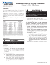
1. Refer to Figure 1. Release the latch on the clamp ring and
remove the ring holding the protective dome to the signal
base. Lift the dome straight up off of the signal base. Remove
the three screws holding the strobe tube support plate to the
signal base, grasp the plate and carefully lift the support plate
off of the signal base.
2. The 94DV2(*)-N5 signal must be conduit mounted.
The signal's lens and dome should be periodically cleaned to
maintain optimum light visibility. These items may be cleaned
with a soft cloth or sponge using water or a mild detergent solu-
tion. Make sure the lens and dome are completely dry before
replacing.
Strobe Tube Replacement
Refer to Table 2 for the required strobe tube.
1. Refer to Figure 1. Disconnect the power and wait five
minutes. Lift the dome off of the signal base. Loosen the
three screws in the keyhole slots in the base of the lens. Turn
the lens clockwise and lift it straight up and off the strobe
tube support plate. Next, remove the three screws holding
the strobe tube support plate to the signal base. Grasp the
socket (on the strobe tube support plate) and carefully lift
the support plate off of the base.
a. Refer to Figure 1. The signal requires a 3/4" (19 mm)
NPT conduit. Route the field wiring from the power
source through the conduit and then through the conduit
entrance hole in the signal base.
b. Install the signal base on the conduit.
3. Using wire nuts (not supplied), connect field wiring to signal
wiring. Connect the green ground wire leads using wire nuts
(not supplied).
WARNING
To reduce the risks of igniting hazardous atmo-
spheres and electric shock, disconnect power and
allow five (5) minutes for stored energy to dissipate
before disassembly.
Do not
connect power until
unit is tightly assembled and secured.
Cleaning
CAUTION
To prevent damage to the lens, do not use abrasive
materials or cleaners.
CAUTION
To prevent damage to the strobe tube, handle the
tube only by the base.
2. To remove the tube from the socket, grasp the base of the
strobe tube and pull firmly, or carefully pry between the strobe
tube base and the socket. Install the new strobe tube by
aligning the key on the strobe tube base with the slot in the
socket and then pressing the strobe tube base onto the socket.
Reassemble the signal.
3. Turn on power and verify that the strobe operates.
*The letter in this position signifies the color of the supplied lens. A - amber, B - blue, C - clear, G - green, M - magenta or R - red.
Cheshire, CT 06410 203-699-3300 (Ph)
203-699-3365 (Cust. Serv. Fax)
203-699-3078 (Tech. Serv. Fax)

P-047550-1384 ISSUE 5
Table 1. Division 2 Locations
Class Division Group Temp. Code
I 2 A, B, C, D T3 (200°C, 392°F)
II 2 F, G T6 (85°C, 185°F)
III T6 (85°C, 185°F)
Figure 1. Mounting the 94DV2 Series Signal
Table 2. Replacement Parts
Catalog Number or
Component Part Number
Xenon strobe tube 92-ST
Dome 94-DC
Lens 93-L(*)
*The letter in this position (A - amber, B - blue, C - clear, G - green, M -
magenta or R - red) signifies the color of the lens; for example, a red lens for
the 94DV2 series signal is 93-LR.
/