Page is loading ...

Catalog
Number Rated Volta
g
e Current
(
A
)
5520-AS 12V 60 Hz 1.3
12V DC 0.7
5520-AQ 24V 60 Hz 0.85
24V DC 0.35
5520-N5 120V 60 Hz 0.35
5520-P1 125V DC 0.1
5520-R5* 240V 60 Hz 0.1
5521-S1 250V DC 0.065
*Requires a separately mounted Cat. No. 598Y
transformer (supplied with signal) to convert
240V AC line voltage to 24V AC.
Description
Edwards' DUOTRONIC signals are heavy duty, high deci-
bel, UL listed signaling appliances intended for use in gen-
eral signaling and alarm applications. The 5520 series of
signals can operate either as a horn or a siren and provide
a switch for selecting the desired operating mode. The
5521-S1 signal operates as a horn only. The horn and si-
ren tones are produced electronically. Signals operating
in the horn mode can be used in coded signaling applica-
tions.
The 5520 series of signals can be installed on any standard
single gang, 3 1/4" (83 mm), 3 1/2" (89 mm), or 4" (102
mm) octagonal, or 4" (102 mm) square electrical box, or
they can be installed outdoors using the Cat. No. 349
Weatherproof Box (ordered separately). Also, the Cat. Nos.
5520-AS and 5520-AQ signals can be direct wall mounted.
The Cat. No. 5521-S1 signal can be installed indoors or
outdoors and is supplied with a Cat. No. 349-R Weather-
proof Box. The box must be used when installing the Cat.
No. 5521-S1 signal indoors as well as outdoors because it
contains a dropping resistor that is required for operation
of the signal.
Electrical Specifications
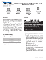
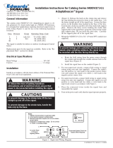
Figure 1. Dimensions
Mechanical Specifications
Dimensions ...........................................See Figure 1
Weight .................................... 7 1/2 Pounds (3.4 kg)
Installation
Install in accordance with the latest edition of the Na-
tional Electrical Code and/or lother applicable codes and
standards.
For Catalog Series 5520, install as follows:
Installation Instructions for Duotronic Signals
Catalog Series 5520 and 5521
P/N P-047550-0437 ISSUE 2 © 2002CHESHIRE, CT 203-699-3300 FAX 203-699-3365 (CUST. SERV.) 203-699-3078 (TECH SERV.)
WARNING
Before beginning the installation of the signal,
ensure that the power source for the signal is
disconnected.
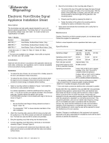
1. Loosen the screw at the bottom of the signal housing
and remove the mounting plate from the signal (Figure
2).
2. Select the desired operating mode by sliding the handle
of the horn/siren switch, located in the rear of the
signal housing, to the applicable selection.
NOTE: For Cat. No. 5520-R5 signal, proceed to step 3.
For all other 5520 Series models, proceed
directly to step 4.
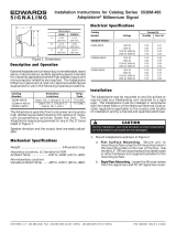
3. Mount the Cat. No. 598Y transformer on an electrical
box. Connect 240V AC power source wires to wire
leads from primary side of transformer using wire nuts
(not supplied) (Figure 4). Connect wires to be run to
signal to 24V terminals on secondary side of
transformer (Figure 4).
4. Install wires from power source, or for Cat. No. 5520-
R5 signal, install 24V power source wires from Cat.
No. 598Y transformer. Install signal mounting plate
using one of the following procedures:
NOTE: "TOP" on mounting plate and on inside of Cat.
No. 349 Weatherproof Box indicates required
position for installation.
a. Direct wall mounting--Cat. Nos. 5520-AS and 5520-
AQ only:
Bring power source wires through hole in wall
and through center hole in mounting plate.
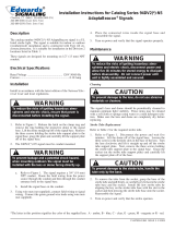
Fasten mounting plate to wall by installing the
three #8 x 1 1/4" (32 mm) wood screws, supplied
with the signal, through the appropriate holes in
mounting plate as shown in Figure 3.
CAUTION
To prevent damage to the signal, always ensure that
power is off before operating the horn/siren switch.

P/N P-047550-0437 ISSUE 2
b. Mounting to electrical box:
Bring wires installed in step 4 through center hole
of mounting plate.
Align appropriate holes in mounting plate with
mounting screw holes in electrical box. Fasten
plate to single gang box using the two #6-32 x 5/
8" (16 mm) screws supplied with the signal, or
fasten to octagon or square box using screws
supplied with the box.
c. Weatherproof installation:
Fasten the Cat. No. 349 Weatherproof Box to the
mounting surface by installing the three
#8 x 1 1/4" (32 mm) wood screws and three fiber
washers, supplied with the box, through the
mounting holes in the rear of the box.
Bring wires installed in step 4 through 3/4" (19
mm)-14 NPT conduit and through conduit entrance
hole into box. Secure conduit to box.
Align appropriate holes in mounting plate with
mounting screw holes in bosses of box and fasten
plate to box using the four #8-32 x 7/16" (11 mm)
machine screws supplied with the box.
5. Connect wires from power source or transformer to
the terminals of the plug receptacle on the mounting
plate as shown in Figure 3.
6. Hook signal on mounting plate by engaging hanger
on plate into slot in top of signal housing (Figure 3).
Press signal flush to mounting plate to mate plug in
rear of signal housing with plug receptacle on
mounting plate. Tighten screw, loosened in step 1, to
secure signal to plate.
For Cat. No. 5521-S1, install as follows:
1. Loosen the screw at the bottom of the signal housing
and remove the mounting plate from the signal (Figure
2).
2. Fasten the Cat. No. 349-R Weatherproof Box to the
mounting surface by installing the three #8 x 1 1/4"
(32 mm) wood screws and three fiber washers, supplied
with the box, through the mounting holes in the rear
of the box.
3. Bring 250V DC power source wires through 3/4" (19
mm)-14 NPT conduit and through conduit entrance
hole into box. Secure conduit to box.
4. Place resistor bracket assembly P-039964-0424 in box
with resistor facing rear of box as shown in Figure 5.
Connect the 250V power source wires to the terminals
on the assembly (Figure 4).
5. Bring the two wire leads from the resistor bracket
assembly through the center hole in the mounting
plate. Align holes in bracket with mounting screw
holes in lower bosses of box when upper conduit
entrance hole is used (Figure 5). When bottom conduit
entrance hole is used, bracket must be aligned with
screw holes in upper bosses in box.
6. Align appropriate holes in mounting plate with
mounting screw holes in bosses of box, and fasten
plate and resistor bracket assembly to box using the
four #8-32 x 7/16" (11 mm) machine screws supplied
with box.
7. Connect wire leads from resistor bracket assembly to
the terminals of the plug receptacle on the mounting
plate (Figure 3).
8. Hook signal on mounting plate by engaging hanger
on plate into slot in top of signal housing. Press signal
flush to mounting plate to mate plug in rear of signal
housing with plug receptacle on mounting plate.
Tighten screw loosened in step 1 to secure signal to
plate.
Adjusting Speaker Direction
To adjust the speaker direction, loosen the nut shown in
Figure 2. Rotate the speaker to the desired position and
tighten the nut. The speaker position can be adjusted
within a 90° range vertically and 180° range horizontally.
Operational Test
Apply power to the signal and verify that it sounds. For
models with horn/siren mode selection, verify that selected
type of signal is sounding.
Maintenance and Subsequent Testing
Examine the signal annually for accumulation of dirt.
Clean if necessary.
Test the signal semi-annually or at the intervals required
by applicable regulations and codes.
Figure 2. Mounting Plate Removal and
Speaker Directional Adjustment

P/N P-047550-0437 ISSUE 2
Figure 3. Mounting Plate Details
Figure 4. Wiring Installation
Figure 5. Resistor Bracket Assembly Installation
/