Page is loading ...

COMDIAL
DIGITECH
Digital Telephone System
System Manual
This publiiion is
@icable
to the
following
COmmoR
#IQ@mmt:
-
CQ408 Rev. A and
l8ter
(
-‘.CX!6$6
Rev. A and kter
’
4$&Z@
Rev. A and later
PKOlO-004
12
MI
66-083.01

Table
Of Contents
TABLE OF CONTENTS
CHAPTER 1 SYSTEM OVERVIEW
.............................
1-l
SECTION 1 INTRODUCTION
.........................................
l-l
SECTION 2 PUBLICATIONS OVERVIEW
..................................
1-2
ManualScope
....................................................
..l-
2
Related Publications
................................................... l-2
SECTION 3 HARDWARE SUMMARY
....................................
1-3
Common Equipment Description
............................................
l-3
Station Description
....................................................
l-3
SECTION 4 GENERAL SPECIFICATIONS
.................................. 1-8
CHAPTER 2 DESCRIPTION OF SYSTEM FEATURES
..................
2-I
Abandoned Hold Release
................................................ 2-l
Access Denied
...................................................... 2-l
Account Code Button
.................................................. 2-l
Account Codes Positive Verification
...........................................
2-1
AtI-Call Paging
......................................................
2-1
Area Paging Interface
..................................................
2-1
AssistButton..
...................................................
..2- 1
Automatic Call-Back
...................................................
2-1
~~~~t-rdc Dialing
....................................................
2-2
Automatic Hold For Intercom
..............................................
2-2
Automatic Hold -Transfer To Intercom
.........................................
2-2
Automatic Hold
-
Transfer To Line
............................................
2-2
Automatic Pause Insertion
................................................
2-2
Automatic
Prbcy
....................................................
2-2
Automatic Redial
.....................................................
2-2
Automatic Station Relocation
..............................................
2-2
Auxiliary Equipment interface
..............................................
2-2
Auxiliary Ringer Interface
................................................
2-2
Background Music
....................................................
2-3
Basic Key Service
(lA2)
Emulation
...........................................
2-3
Battery Back-Up
......................................................
2-3
Battery Back-Up
Interface
................................................
2-3
Block Programming
...................................................
2-3
Call Announce Wiih Handsfree Answerback
......................................
2-3
Call Costing And SMDA Reports
............................................
2-3
Call Forwarding
On
All Calls
...............................................
2-4
Call Forwarding
-
Personal
...............................................
2-4
CallPark
.......................................................
..2
-4
Call Pickup
-
Directed
..................................................
2-4
Call Pickup
-
Group
...................................................
2-4
Call Transfer
-
Screened
.................................................
2-4
Call Transfer
-
Unscreened
...............................................
2-5
CalI
Waiting
Tone
....................................................
2-5
Calling Station Identification On BLF
..........................................
2-5
Class Of Service Programming (From Main Station)
...................................
2-5
Class Of Service Programming (From VDT)
......................................
2-5
Class
of
Service Program Printout
...........................................
2-5
Common
Audible
Ringer
Interface
............................................
2-5
&nferencing
-
Add-On
.................................................
2-6

Table Of Contents
IMI
66-r-
Conferencing
-
Multiline
.................................................
2-6
Conferencing
-
Unsupervised
..............................................
2-6
DataSecurity
....................................................
..2- 6
Default Functional Program
...............................................
2-6
Defautt Toll Restriction
..................................................
2-6
Delayed Ringing
.....................................................
2-6
Departmental Calling Distribution Report
........................................
2-6
Designated Programmable Buttons
...........................................
2-7
Dial 0 For System Attendant
...............................................
2-7
Direct Department Calling With DCD
...........................................
2-7
Direct Inward Station Dialing
..............................................
2-8
Direct Station Call Hold
.................................................
2-9
Direct Station Selection Programmable
.........................................
2-9
Distinctive Ringing
....................................................
2-9
Do Not Disturb
......................................................
2-9
Do Not Disturb Inhibit
..................................................
2-9
Do Not Disturb Override
.................................................
2-9
Dual Intercom
......................................................
2-g
Dynamic Line Buttons
..................................................
2-9
End-To-End Signalling On Intercom
..........................................
.2-l
0
End-To-End Signailing On Lines
............................................
2-9
Exclusive Hold
......................................................
2-9
Exclusive Hold System-Wide Enable/Disable
.....................................
.2-l
0
Executive/Attendant Override
.............................................
.2-l
o
External Paging Interface
...............................................
.2-1 o
Feature Inhibit
.....................................................
.2-10
Flexible Ringing Assignments
.............................................
.2-l
o
Flexible Ringing Assignments Of PA Port
.......................................
.2-l o
Flexible Station And Line Class Of Service Control
..................................
.2-l
1
Flexible Station Numbering Plan
...........................................
.2-l
o
Full Button Programmability Of Features
.......................................
.2-f
o
Handsfree Answer Inhibit
...............................................
.2-l
1
IHoldAndIUselndications
..............................................
.2-11
Idle Line Preference
..................................................
.2-11
intercom Call Progress Tones
.............................................
.2-l
1
IntercomHuntGroup
..................................................
.2-11
Intercom Line Timeout
.................................................
.2-l
1
Last Number Redial
..................................................
.2-l 1
LCD Messaging
....................................................
.2-12
LCDSupport.......................................................2-1
2
Line Access Restriction
................................................
.2-12
Line Answer From Any Station (Night Mode)
.....................................
.2-12
Line Groups
......................................................
.2-12
Line Preselection
...................................................
.2-12
Line And Line Group Queuing
.............................................
.2-12
Manual Hold
......................................................
.2-12
Meet-Me Answer Page
................................................
.2-l
2
Memory Retention Without Batteries
.........................................
.2-l
2
Message Waiting
...................................................
.2-12
Modular Wring And Jacks
...............................................
.2-13
Music
Interface
.....................................................
.2-13
Music-ChpHoltj
...............................
.F.
....................
.2-13
Music-On-Hold System-Wide Enable/Disable
.....................................
.2-13
Ml&
......................................................... ..2-13
Night
Transfer
(Of Ringing)
..............................................
.2-13
On-Hook Dialing
....................................................
.2-13
Iv

.lJll
otPutr3
Table Of Contents
Originating Denied
...................................................
.2-l
3
PBXICENTREXICO Compatible
............................................
.2-13
Personalized Ringing Tone
..............................................
.2-l
3
Pooled Line Access
..................................................
.2-13
Power Failure Transfer
................................................
.2-l
3
Prime Line Automatic
.................................................
.2-13
Privacy
-
Designated Programmable Button
.....................................
.2-l
4
Privacy Release/Brokerage Service
..........................................
.2-14
Private Lines (Access Denied)
.............................................
.2-14
Programmable Direct Station Selection/Busy Light Field
...............................
2-14
Programmable Buttons
................................................
.2-14
Pulse/Tone Switchable
................................................
.2-14
Response Messaging
.................................................
.2-14
Remote Programming And Administration
......................................
.2-14
Ringing Line Preference
................................................
.2-14
Saved Number Rediat
.................................................
.2-l
4
secure Off-Hook Voice Announce
...........................................
.2-14
secure Off-Hook Voice Announce Button
.......................................
.2-l
5
Secure Off-Hook Voice Announce Groups
......................................
.2-15
Self Diagnostics
....................................................
.2-16
Service Observing
...................................................
.2-16
Speakerphone Support
................................................
.2-16
SquareNon-Square Configuration
..........................................
.2-16
Station By Station Privacy
...............................................
.2-l
6
Station Message Detail Accounting
..........................................
.2-l
6
Station Message Detail Recording
..........................................
.2-16
Station Monitoring With DSS Call Pickup
.......................................
.2-16
Station Speed Dial
...................................................
.2-16
Station-To-Station Messaging
.............................................
2-l 6
Subdued Ringing
...................................................
.2-17
System Alarm Reports
.................................................
.2-17
System Speed Dial
..................................................
.2-17
Tandem Attendant
...................................................
.2-17
Tap
(Flash)lRecafl
....................................................
.2-37
Tenant Service
.....................................................
.2-17
Timed Hold Recall
....................................................
.2-17
Toll Restriction (0 And 1)
...............................................
.2-17
Toll Restriiion (Flexible)
...............................................
.2-l
7
Toll Restriction (Night Mode)
.............................................
.2-17
Tone Or Voice Signalling (Intercom)
..........................................
.2-l
8
Transfer/Conference Button
..............................................
.2-l
8
Unanswered Call Transfer Recall Timing
.......................................
.2-l
8
Voice Announce Blocking
...............................................
.2-18
Voice Mail Transfer on Busy
..............................................
.2-l
8
Zone Paging (Via Station Speakers)
.........................................
.2-l
8
CHAPTER 3 INSTALLATION
................................
3-l
SECTION
i
STANDARD
INSTALLATION
DETAILS
.............................
3.1
Mounting Considerations
................................................
3-l
Mounting Procedure
...................................................
3-l
AC Power Connection
...........................
:
......................
3-3
System Grounding
....................................................
3-3
Line Connections
....................................................
3-5
Station Connections
...................................................
3-5
V

Table Of Contents
IMI
66,’
SECTION 2 OPTION INSTALLATION DETAILS
...
,
...
,
......................
3-14
Key System/Hybrid Configuration
...........................................
.3-l
4
Power Failure Station Connections
..........................................
.3-l
5
Auxiliary Equipment Interface
.............................................
.3-l
6
Common Audible And Auxiliary Ringing interface
...................................
.3-l
7
External Paging Interface
...............................................
.3-l
8
External Paging Interface
-
Line Port
.........................................
.3-l
9
Data Device Connections
...............................................
.3-20
Music Interface
.....................................................
.3-22
SECTION
3 ADD-ON EXPANSION MODULES
..............................
3.23
Introduction
......................................................
.3-23
Installation
.......................................................
.3-26
SECTION 4 SOFTWARE CARTRIDGE ,
..................................
3-27
Introduction
......................................................
.3-27
Installation
.......................................................
.3-27
SECTION
5 DATA COMMUNICATIONS WITH THE DIGITALTELEPHONE SYSTEM
..........
3-29
Equipment Required
..................................................
.3-29
Connections
......................................................
.3-29
Communications Procedures
.............................................
.3-29
SECTION 6
SYSTEM CHECKOUT AND FAILURE
ISoLATloN
..........
,
...........
3-31
Initial Condition
....................................................
.3-31
Checkout ......................................................
..3-3 1
Resistance Check
...................................................
.3-31
VoWe
Check
......................
,
..............................
.3-31
General Check
.....................................................
.3-31
Failure Isolation
....................................................
.3.31
SECTION 7 FCC RULES AND REGULATIONS
..............
,
...............
3.32
CHAPTER 4 SYSTEM PROGRAMMING
.........
,
................
4-1
SECTION
i
GENER
A
L INFORMATION
...................................
4-j
Programming Overlays
.................................................
4-1
SECTION 2 CLASS OF SERVICE PROGRAMMING
.............................
4.2
Master Clear
.......................................................
4-3
System Defautts
.....................................................
4.4
System Configuration
..................................................
4-5
Line Configuration
...................................................
.4-14
Station Configuration
.................................................
.4-22
Direct Inward Station Dialing
.............................................
.4-53
Analog Terminal Interface
...............................................
.4-55
Toll Restriction Table Configuration
..........................................
.4-58
Data Printer Service
..................................................
.4-64
Integrated Call Costing
................................................
.4-65
Station Message Detail Accounting Reporting
....................................
.4-74
Attendant Configuration
................................................
.4-78
SECTION 3 VIDEO DISPLAY TERMINAL PROGRAMMING
.......................
4-83
lntdu&n
.4-83
..................
:
...................................
VDT Programming Procedure
.......................
.,
.....................
.4-83
Remote Programming
.................................................
.4-84
Typical PC Operation
.................................................
.4-84
Menu Descriptions
...................................................
.4-87
Main Menu Selections
.................................................
.4-87
vi

Table Of Contents
System COS Menu Selections
............................................
.4-87
Line COS Menu Selections
..............................................
.4-88
Station COS Menu Selections
.............................................
.4-89
Toll Restriction Table Administration
.........................................
.4-90
CHAPTER 5 SYSTEM OPERATING PROCEDURES
....................
5-l
SECTION 1 STATION OPERATION
.....................................
5-l
Answering Calls
.....................................................
5-1
Making Calls
.......................................................
5-2
Holding Calls
.......................................................
5-4
Transferring Calls
....................................................
5-4
Conferencing
.......................................................
5-5
Messaging
........................................................
5-5
Voice Announce Blocking
................................................
5-6
Line Monitoring
.....................................................
5-6
Recall/Flash
.......................................................
5-6
Paging
..........................................................
5-7
Do Not Disturb
......................................................
5-7
MuteIHandsfree Answer Inhibit
.............................................
5-8
Pulse/Tone Switching
..................................................
5-7
Personal Ringing Tones
.................................................
5-8
Background Music
....................................................
5-8
CaltFonvard
.....................................................
..5- 9
Automatic Call-Back
...................................................
5-9
CallWaiting
.....................................................
..5
-9
Service Observing
...................................................
.5-lo
Executive Override
...................................................
-5-l
0
Speakerphone Operation
...............................................
.5-l
1
Departmental Station Operation
............................................
.5-l
I
Station User Programming
...............................................
.5-l
1
SECTION 2 ATTENDANT STATION OPERATION
.............................
5-14
System Clock
.....................................................
.5-14
System Speed Dial Programming
...........................................
.5-14
Night Transfer (Of Ringing)
..............................................
.5-14
Music On Hold
.....................................................
.5-15
LCD Messaging
....................................................
.5-15
Station Names
.....................................................
.5-15
Station Message Detail Accounting (SMDA) Printout
.................................
.5-l
7
System Alarm Reporting
................................................
.5-17
Direct Inward Station Dialing
.............................................
.5-17
SECTION 3 SYSTEM OPERATlNG CHARACTERISTICS
.........................
5-19
Feature Code Numbering Plan
............................................
.5-l
9
Ringer
Volume
Control
.................................................
.5-21
Status Indicators And Tone Sequences
........................................
.5-21
Display
Intensity
....................................................
-5-21
CHAPTER6 MAINTENANCE
............................
,
...
6-I
Technical Assistance And Repair Service
........................................
6-1
Fuse Location
.......................................................
6-1
Wiring
..........................................................
6-1
Station Wall Mounting
..................................................
6-1

Table Of Contents
IMI
66
’
Figure l-1.
Outline Dimensions
-
Common Equipment
............................... l-5
Figure l-2.
Outline Dimensions
-
Station Equipment
................................
l-6
Figure 1-3.
Station Images
..............................................
l-7
Figure 3-l.
Mounting Dimensions
..........................................
3-2
Figure 3-2. AC Power Connection And System Grounding
.............................
3-4
Figure 3-3.
Common Equipment, Station And Line Connections
.........................
.3-l
1
Figure 3-4.
Typical Line Connections
........................................
.3-l
2
Figure 3-5. Typical Station Connections
......................................
.3-l
3
Figure 3-6.
Key/Hybrid Configuration
.......................................
.3-l
4
Figure 3-7.
Power Failure Connection
.......................................
.3-l
5
Figure 3-8. Auxiliary Interface Connections
....................................
.3-l
6
Figure 3-9. Typical Common Audible Interface Wiring
...............................
3-l 7
Figure 3-l 0.
Typical External Paging Connection
..................................
.3-l
8
Figure 3-l 1. Typical External Paging Connection
-
Line Port
............................
3-l 9
Figure 3-12.
Typical Data Device Connections
...................................
.3-21
Figure 3-13.
Music Interface
.............................................
.3-22
Figure 3-l 4.
Add-On
Expansion Module Configuration
...............................
.3-24
Figure 3-l 5.
Expansion Module Installation
.....................................
.3-26
Figure 3-l 6. Software Cartridge Installation and Removal
.............................
3-28
Figure 3-l 7.
Data Communications Interconnection Diagram
............................
.3-30
Figure 4-l.
Location Of Keys On Telephone Faceplate
..............................
4-49
Figure 4-2. Call Costing Diagram
..........................................
.4-67
Figure 4-3.
Remote Programming Block Diagram
.................................
.4-86
Figure 5-l.
Controls and Indicators
.........................................
.5-l
8
Figure
6-1.
Station Wall Mounting Details
......................................
6-2
Programming Overlays
.............................................
.4-91,4-92
LIST OF TABLES
LIST OF ILLUSTRATIONS
Table
3-l.
Line Connections
.............................................
3-6
Table 3-2.
Station Connections (CLine, E-Station)
.................................
3-7
Table 3-3. Station Connections (E-Line,
16Btation)
................................
3-8
Table
3-4a. Station Connections (16-Line,
3PStation)
................................
3-9
Table 3.4b.
Station Connections (16-Line,
32Station)
...............................
.3-l
0
Table 3-5. Line Connections
-
408 Expansion Module
..............................
3-23
Table 3-6.
Station Connections
-
408 Expansion Module
.............................
.3-25
Table
4-l.
Character Dialing Codes Chart
....................................
-4-21
Table
5-l.
Character Codes
............................................
.5-l
6

CHAPTER
1
SYSTEM OVERVIEW
System Overview
SECTION 1
INTRODUCTION
The digital telephone system is an expandable
communications system with many attractive
characteristics including the following:
Unitized base unit which includes all system
features.
The base unit is full featured and
self-contained.
Expansion modules which increase station and
line capacity.
A 4-line, 8-station expansion module is
available. It can be added singly or in pairs to
increase the station and line capacity of an existing
base unit installation.
Secure off-hook voice announce (SOHVA) feature.
The SOHVA feature allows a station user to talk to a
busy station without being heard by the outside party
at the busy station. The called user can easily send
back a pre-programmed LCD message or talk to the
caller without being heard by the outside party.
Programmable buttons.
Many of the telephone
buttons can be programmed to provide functions such
as direct station selection (DSS), auto dial, system
feature access, line access, messaging and more.
Programmed buttons helps station users eliminate
manual dialing errors.
Service
observing.
Supervisors can help insure
quality of service without interrupting calls by
monitoring a trainee’s call without being heard by the
distant party at the trainee’s station.
Handset volume control on all stations.
Handset
volume can be set to a comfortable listening level for
each individual user of the telephone.
Call cost display.
Built-in software records all
outside call costs. Special programming allows an
LCD speakerphone to display the accumulating cost of
a call.
Dual intercom.
A second intercom key can be
provided so that station users can handle two intercom
calls at once. One intercom call can be placed on
hold while a second intercom call is serviced or both
calls can be conferenced together.

System Overview
IMI
66.
SECTION 2
PUBLICATIONS OVERVIEW
MANUAL SCOPE
This publication contains a technical discussion of the
digital telephone system. Included in this manual is
the following information:
Chapter 1, System Overview:
This chapter
provides a generalized understanding of the
system, an explanation of the supporting
documentation, and a summary of the equipment
hardware.
Chapter 2, Feature Description:
This chapter
provides a detailed discussion of the features
provided by the digital telephone system.
Chapter 3, Installation:
This chapter provides
detailed installation instructions and connection
details.
Chapter 4, Programming:
This chapter provides
detailed programming instructions for setting the
operating parameters of the system.
Chapter 5, Operation:
This chapter summarizes
operating procedures and provides special tone
and indicator details.
l
Chapter 6, Maintenance:
Special maintenance
details are provided in this chapter.
RELATED PUBLICATIONS
Related publications, which contain additional
information applicable to this system, are available
from the manufacturer.
They are as follows:
GENERAL INFORMATION
l
IMI 01-005 Handling
of
Electrostatically Sensitive
Components
USER INFORMATION
l
GCA 70-l 82 Attendant’s Guide
l
GCA 70-l 83 System User’s Guide
l
GCA 70-l 84 Station User’s Guide

.
..a.
au-u83
SECTION 3
HARDWARE SUMMARY
System Overview
The digital telephone system consists of an electronic
Key Service Unit (KSU) base unit, usually referred to
as common equipment, optional expansion modules to
extend station and line capacities as required, a
software cardridge containing the operating
System
programming, dedicated digital electronic key
telephones, and interconnecting wiring consisting of
small, 2-- or 4--conductor, twisted-pair cable.
The station and line capacity of the base unit and
optional expansion module are per the following chart.
MODEL
CO/PBX
STATION
NO.
CAPACITY
CAPACITY
CO408 4
8
CO81 6
8
16
Cl 632
16
32
CM408 4 8
The digital telephone system is full featured, and
supports the digital telephone models.
The digital system is expandable in both line and
station capacity with the addition of add-on expansion
modules. Refer to
Figure 3-14
on page 3-24 for an
illustration of the expansion configurations.
COMMON EQUIPMENT
DESCRlPTlON
The common equipment base unit is a fully electronic
device. It is essentially a special purpose computer
system acting as a communications controller
between central off ice (CO), private branch exchange
(PBX), or
CENTREX
supplied lines and the proprietary
digital telephone stations. The software architecture
of the common equipment provides complete system
support
and
great flexibility of operation.
The system is fully digital and is ISDN up-gradable
with two usable time slots available for each station.
The digital information passes over time division
multiplexing (TDM) highways. The digital information
is an encoded version of the voice transmission and
control signals that are translated into computer
language. The TDM highway can transmit several
signals over a single pair of wires at the same time.
The signals are governed by a system clock. This
clock creates an overall point of reference against
which the TCM information is synchronized and
partitioned into time slots. A time slot is a portion Of
time assigned to a particular position of the system
clock. Each time a particular clock position
iS
reached, the information associated with that position
can be read. As the system clock goes through the
clock cycle, all necessary digital information is passed
between the pieces of equipment sharing the highway.
The common equipment consists of a base unit, which
provides complete feature support, and optional
expansion modules which provide extended station
and line coverage.
The wmmon equipment is contained in a functional,
modem-style metal housing of contemporary design in
keeping with the needs of the modem off ice
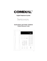
environment. It is engineered to be wall or rack
mounted. The outline dimensions of the common
equipment base units are illustrated in
Figure l-l.
STATION DESCRIPTION
The digital telephone stations employed with the
digital system are electronic, microprocessor-
controlled, devices. They allow not only multiline
pickup but also single key access to features available
from the serving CO, PBX, or
CENTREX
switch
as
well as the wmmon equipment. The digital telephone
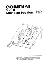
is available in two different images. The features of
the images are as listed below and as detailed in
Figure
l-2
and in
Figure
l-3.
The wide-image digital telephone provides the
following features:
l
Full modular connection
l
3 fixed buttons with indicators
. SPKR
l HOLD
.
ITCM
3 fixed buttons without indicators
l TAP
.
TRANS/CONF
. MUTE
Programmable buttons with indicators
7-foot, G-conductor line cord
6 position, 4- or 6-conductor modular line jack
K-type handset (hearing aid compatible)
Ringer volume control (Off, Low, and High)
Wall mounting capability

System Overview
IMI 66
The image designations refer to the number of
programmable buttons located below the keypad,
including the hold and intercom buttons, as opposed
to the number of programmable buttons located above
the keypad.
available in both monitor and speakerphone
versions.
l
The LCD speakerphone is available in a 5x14
image, This image provides a priority line grouping
and contains a liquid crystal display which shows
l
The 10x14 image provides a moderate sized line
call handling data and other usefutinformation. The
button matrix along with a moderate sized priority
LCD speakerphone is used as an attendant station
line button grouping. This image is best suited for
as well as being very applicable for use as an
typical work area stations. The 10x14 image is
executive station.
l-4

System Overview
I-
+
&Line,
Mtatlon
Base Unit
I--
Id
+
1
7
-I
-7.44
+-
{-
16.50
,-I
“.
“:~:x:%:~:::~:z:
:~:~:“:::::::m:x:::~:
gg:““:“:t:.c:“:n:zm:
.
.
.
.
.
.
.
.
.
.
.
.
I==/
.
x
.
I
:
1
q
0
26:35
I
I
I
Z?
26.25
1
+-
2.13
+-I
&Llne, 16Statlon Base Unit
t-
14
.8
t
+
2
7
-7.44
-=I
+,
2
-
16.50
-
I
1
i
0
27
?6
-I-
!
I
+
2.89
-c-l
%-Line. 3%Station Base Unit
Figure 1-l. Outline Dimensions
n
Common Equipment
l-5

System Overview
l-6

_-
d33 System Overview
J
0
I’r
0
0
0
t
0
0
0
0
0
0
0
0
0
l-7

System Overview
IMI
66-u,.
SECTION 4
GENERAL SPECIFICATIONS
4-LINE,
8-LINE, 16-LINE
8-STATION,
16-STATION 32STATION
SYSTEM CAPACITY
LINES:
STATIONS:
DSSBLF CONSOLES:
INTERCOM PATHS:
MAXIMUM SIMULTANEOUS
INTERCOM CONVERSATIONS:
PAGING PORTS
PARK ORBITS
SPEED DIALS
SYSTEM
STATION
AUTODIALS
POWER FAIL CIRCUITS
CONFERENCING
(Maximum Combinations
At Any One Time)
POWER REQUIREMENTS
(Fully loaded system)
AC POWER:
DIMENSIONS (approximate)
COMMON EQUIPMENT
WIDTH (inches):
HEIGHT(inches):
DEPTH (inches):
WEIGHT (pounds):
STATIONS
FOOTPRINT (inches):
WEIGHT (pounds):
STATION CABLE REQUIREMENTS
TYPE:
MAXIMUM LENGTH:
SWITCHING PRINCIPLE:
4
8
16
8
16
32
(FUTURE FEATURE)
Non-blocking
Non-blocking Non-blocking
Non-blocking Non-blocking
Non-blocking
1
1 1
9 9
9
99
99 99
10
10
10
Unused buttons
Unused buttons Unused buttons
1
1 1
1
five-way plus 1 three-way
4 five-way plus 5 three-way
plus 2 SOHVA
plus 1 SOHVA
2 four-way plus 2 SOHVA
6 four-way plus 2 three-way
1
four-way plus 3 three-way
3 four-way plus 9 three-way
5 three-way plus 1 SOHVA
16 three-way
90
-
129 VAC Singlephase
-
all models
0.6A 2.0 A 2.1A
7ow 135w
150w
8OVA 19OVA
200VA
16.5 16.5 16.5
21.3
27.1 27.6
3.8 3.8 4.5
17.5 26
30.5
8.625 X 7.658
2.5
P-wire (l-pair) twisted, non-shielded.
1000 feet with 24 gauge wire
Digital, time division multiplexing (TDM). Provides non-blocking
switching with stored program control

dysrem Overview
IMI 66-083
OPERATlNG ENVIRONMENT
TEMPERATURE:
HUMIDIlY:
TEFlMlNATlONS
STATION:
LINE:
STATlON MESSAGE DETAIL
RECORDING PORT
FORMAT:
PARITY:
DATA BITS:
STOP BITS:
BAUD RATE:
HANDSHAKING:
CABLE LENGTH:
MUSIC INTERFACE
INPUT LEVEL:
INPUT IMPEDANCE:
CONNECTOR:
PA PORT
OUTPUT LEVEL:
OUTPUT IMPEDANCE:
CONNECTOR:
CENTRAL OFFICE LIMITS
LOOP LIMfTS:
CABLE INSULATION LEAKAGE:
INDUSTRY/REGULATORY
STANDARDS:
MEMORY RETENTlON
AFTER POWER LOSS:
FCC REGlSTRATlON NUMBER:
KEY SYSTEM:
HYBRID SYSTEM:
RINGER EQUIVALANCE NUMBER:
PRODUCT CODES:
CO408
-
4-Line
,8-Station
CO81 6
-
a-Line, 16Station
Cl 632
-
16-Line,
32-Station
CM408
-
4-Line, a-station
Expansion Module
32-122 degrees F (O-50 degrees C)
90 percent relative, non-condensing
Standard 50-pin male connectors for connection to external
distribution field.
Standard, G-conductor mini-jack (USOC 14C)
Serial, pseudo RS-232C
None
7 or 8 (programmable)
1 or 2 (programmable)
Programmable in class of service
Xon
-Xoff
Hardware
-
CTS
500 Feet maximum
3 Vofts peak-to-peak maximum
Approximately 500 Ohms
RCA phono jack
400 Millivolts peak-to-peak (typical speech)
Approximately 500 Ohms
RCA phono jack
1900 Ohms maximum loop
15,000 Ohms minimum
FCC Certified, part 15 (Class A)
FCC registered (fully protected)
LISTED by OSHA-accredited, nationally recognized, test laboratory
EIA RS478
Bell publication 48002 guidance
Hearing aid compatible handset
60 hours minimum
CWVUSA-61535-KF-E
CVWUSA-61536-MF-E
1.38
ware
Cartndgg
7714X
-
1 OX14 Image Monitor
7714s
-
1 OX14 Image Speakerphone
7700s
-
5X14
Image LCD Speakerphone
SO408
SO816
S1632

IMI 66-083
DeSCriDtiOn
of
Svstem
Feat3
CHAPTER 2
DESCRIPTION OF SYSTEM FEATURES
ABANDONED HOLD RELEASE
If an on-hold party hangs up at the CO/PBX end of a
connection, causing an interruption in the line current,
the system will drop the line from the hold condition
and return it to service. The time interval between
hang-up and line-drop is programmable in line class of
service programming with choices of either 50 msec or
350 msec. This feature is usually dependent upon
special arrangements that must be made at the CO
end of the connection. The line select indicator will
turn off to indicate an idle line after a call on that line
hasbeenabandoned.
ACCESS DENIED
Access to particular lines can be denied at certain
stations in the system through system programming.
A station user cannot select a denied line for use.
This feature is programmable on a per line/per station
basis in station class of service programming.
ACCOUNT CODE
BUITON
Station class of service programming can be used to
assign an Account Code button to any programmable
button location at a station as part of the button
mapping procedure. With this Account Code button
available, the user can press it and then dial the
account code without interrupting the call. Only the
user of the Account Code button will hear the DTMF
tones when the code is dialed. The distant on-line
party will not hear the DTMF tones, and the line will
not be placed on hold. The distant on-line party can be
heard while the account code is being dialed.
ACCOUNT CODES WITH
POSITIVE VERIFICATION
Specific account codes can be assigned by station
users to specific types of calls. The account codes
are used by the system to identify calls by category, or
special grouping, for call recording purposes. All calls
with the same account code will be reported together
by the station message detail accounting feature.
The system may be programmed to verify the user
entered account code and sound an ermr tone if it is
incorrect. The system may be programmed by call
costing and SMDA reporting class of service
programming to permit station users to enter account
codes for incoming calls and/or out going calls if
desired. Account codes are entered while on line
either before an out going call is dialed or after the
distant patty on an incoming call has hung up. On out
going calls, the user who enters the account code is
associated with the call record except when the call is
transferred. On transferred calls, the transferee is
associated with the call record. On incoming calls, the
last user active on a call is the one that is associated
with the costed call record. The system can be
programmed to place an appropriate message on the
display to remind users of LCD speakerphones to
enter an account code. Account codes may be from
three to eight digits in length as set by class of service
programming. When the user enters an account code,
the system will force the use of the programmed
length, but will verify only the first three digits to
determine validity.
ALL-CALL PAGING
All-call paging allows all stations to receive
announcements through the station speaker at once.
All-call paging is also sent to the paging port where it
can be applied to the input of an external paging
amplifier. Origination of announcements must be via
the station handset. Each station can be programmed
to receive and/or originate all-call page. The ability to
receive and originate all-call paging at a station is
enabled by station class of service programming. Also
see the discussion titled: Zone Paging.
AREA PAGING INTERFACE
Refer to the discussion titled: ExternalPaging
Interface.
ASSIST
Bull-ON
This feature allows a station user to program a button
to be used for sending a message to an LCD
speakerphone. Once programmed, the station user
can press the ASSIST button at anytime and then
press a DSS button to sound a tone burst at the called
station and present a preprogrammed message in the
station display. A message can be sent while on a call
without alerting the distant party. This feature is useful
for requesting assistance while engaging on a call. For
example, a customer service representative could
request assistance from a supervisor while talking to a
problem caller. The supervisor, upon receiving the
tone and noting the display message, could perform
an executive override or service observing action to
join the call or monitor it.
AUTOMATIC CALLBACK
If a busy tone is encountered after an intercom station
is called, a special code number can be dialed that will
cause the system to automatically ring the calling and
called stations when the called station becomes idle.
2-l

No class of service programming is required to enable
this feature.
AUTOMATIC DIALING
The system supports up to 22 auto dial positions per
station. Autodial buttons can store up to 16 digits plus
an intercom or line selection. Stored digits include
9-0,
++
and #. A pause is stored at any point where the
HOLD button is pressed, and a hookflash is stored at
any point where the TAP button is pressed. Automatic
dialing can be used to provide one-button access to
system features. No class of service
programming is required to enable autodialing. Also
refer to discussions titled: Automatic Pause Insertion,
Station Speed Dial, and Programmable DSS/BLF.
AUTOMATIC HOLD FOR INTERCOM
If the second intercom line is selected while a call is
active on the first intercom line, this feature causes the
first intercom call to be automatically placed on hold.
Station class of service programming is required to
enable this feature.
AUTOMATIC HOLD
-
TRANSFER TO
INTERCOM (ANSWER HOLD)
If the intercom line is selected while an outside line
call is active, this system feature causes the outside
call to be automatically placed on hold. No class of
service programming is required to enable this feature.
AUTOMATIC HOLD
-
TRANSFER TO LINE
This system feature is made available through
programming to selected stations. When enabled,
pressing any line button will cause an active line to
automatically go on hold. This feature allows a user to
move from line to line without having to press the
HOLD button to place any current calls on hold.
Station class of service programming is used to
enable this feature at the desired stations.
AUTOMATIC PAUSE INSERTION
When the system stores a dialed number for later
redial, it automatically stores a pause whenever the
user watts between digits for at least two seconds.
The automatic pause is inserted in the stored number
sequence at the point where the manual pause in
dialing occurred. The length of the pause is fixed at
two seconds by the system.
AUTOMATIC PRIVACY
A line can be made private or non-private through
programming. In the private mode, a station has
exclusive use of the line during a call.
No other Station
can access that line unless it is included through
the
-rVI
@on
Of System Features
IMI 66-083
use of the add-on conference feature. In the
non-private mode, another station with that line
appearance can gain access at the same time
(sometimes known as common line pickup). A line is
specified as private or non-private through the line
class of service programming. Through station class
of service programming, a line can be made
non-private at a particular station. Also see the
discussions titled: Conference
-
Add-On and Privacy
Release.
AUTOMATIC
REDIAL
OF BUSY
NUMBER OR UNANSW
i
RED CALL)
A busy number or unanswered call can be
automatically redialed by activating this feature. Once
automatic redial is activated, the station will select the
line, automatically dial the number, and wait for a
response. It will do this once a minute for
approximately 10 minutes unless deactivated because
that button or another button is pressed or the handset
is lifted. The feature cycle is timed and does not have
busy detection circuitry. Because of this, if operating
handsfree when the called party answers, the handset
must be taken off-hook to prevent the caller from
being cut off by the timing cycle. Automatic redial is a
designated programmable button position and must be
programmed by the user to be active but no class of
service programming is required.
AUTOMATIC STATION RELOCATION
With this feature, the system will automatically
recognize a particular station should that station be
relocated to a new station port. When installed at the
new pori location, the station will continue to provide
the same class of service parameters and respond
ta
the same extension numbers as it did at the original
station port. This system feature is enabled with
system class of service programming.
AUXILIARY EQUIPMENT INTERFACE
A non-key system telephone device or a data device
can be connected to a line ahead of the common
equipment by using the auxiliary equipment interface.
The system can detect an off-hook condition in the
device connected to the auxiliary equipment interface,
and turn on the status light for that line at the button
system telephones.
tt
does this to indicate that the
line is busy and not available for station use. Auxiliary
equipment interface connections provide connections
to lines 2 and 4. Pressing the line button on a system
station cannot interrupt an external device unless the
line has been programmed to be non-private.
AUXILIARY RINGER INTERFACE
The auxiliary ringer interface provides “dry-contact”
relay closures which track the ringing pattern
2-2

activated when station port 17 rings or when ringing
iS
sent to the paging port.
When programmed for station port
7
7 ringing, an
external device is often used to provide loud ringing.
When programmed for paging port ringing, an external
paging amplifier is usually employed. The system
supplies ringing tones to the paging port along with the
relay closures. The ringing tones can be sent to the
input of an external paging amplifier. The relay
closures can be employed to energize the paging
amplifier while the ringing tone is being sent to it.
System class of service programming is used to
choose either the paging port. or station port 17 for the
ringing port relay control. System class of service also
determines the type of ringing sent to the paging port.
Station class of service programming determines the
type of ringing sent to station port
17.
Also refer to the
discussions titled: Common Audible Ringer
/fIrerfaCe
and External Paging Interface.
BACKGROUND MUSIC EXTERNAL
MUSIC SOURCE RE6
UIRED)
If an external music source is provided, background
music can be turned on and off at individual stations.
The loudness of the background music is adjusted with
the call monitor speaker volume control, and the
background music automatically turns off during calls.
No class of service programming is required to provide
this feature. Also refer to the discussion titled: External
Music Source.
BASIC KEY SERVICE
(lA2)
EMULATION
The system provides all of the basic, 1 A24ype, button
service features. These features are: selective line
pickup, common line pickup, muftiline pickup, and
hold. No special class of service programming is
required.
BATTERY BACK-UP
(CHASSIS, CABLE, AND BATTERIES)
Battery back-up assemblies including chassis, cable,
fuses, and batteries are offered as optional kits
(available from Comdial). The assemblies are
designed to connect directly to the unintenuptable
power source (UPS) interface located on the common
equipment chassis. No user intervention is required
with this feature, and no class of service programming
is required.
BAlTERY
BACK-UP INTERFACE
Provision has been made for attaching a Comdial
provided optional battery back-up
kt
to give full
uninterrupted system power in case of an AC power
loss. The switching and charge circuitry are in the
common equipment, while batteries, chassis, and
cable are packaged as a separate option. When
plugged into an active AC power source the common
equipment will constantly charge the attached
batteries. Built-in circuitry automatically switches to
battery power when AC power is lost. Wrth batteries at
full charge, a fully loaded system will operate for a
minimum of one hour without AC power.
BLOCK PROGRAMMING
A class of service assigned to a particular station or
line can be assigned to an entire block of stations or
lines with one programming action. This feature
eliminates the need to individually program stations
and lines wfth the same class of service. Block
programming class of service can be performed after a
station class of service or line class of service has been
programmed for a particular station or line.
CALL ANNOUNCE WITH HANDSFREE
ANSWERBACK
The internal speaker at each station provides
call-announce capability over the intercom link. A
handsfree response to a call-announce call can be
made. This response is transmitted by the microphone
built into the telephone housing..
CALL COSTING AND STATION MESSAGE
DETAIL ACCOUNTING REPORTS
The system provides buift-in, estimated costing of all
outside calls.
tt
also provides station message detail
accounting (SMDA) printout reports of all costed calls
as well as displayed call costs on LCD speakerphones.
Call costing, in general, provides a means of
’
establishing costs to be applied to outside calls made
from system telephones. Call costing computes
charges for a call after it is completed. lt does not
restrict dialing as toll restriction does. Call costs are
based on a two-tier time rate and includes a line
surcharge cost. Allowances can be programmed for
call set-up and minimum call duration. The system
provides several ways of determining call costing
making it is possible to apply reasonable rates for the
entire country.
The system is arranged to automatically provide a
report whenever the costed call storage reaches 95
percent of capactty. Additionally, programming can be
effected that causes these reports to be printed
automatically at a specific time of day.
There are five different SMDA reports which can be
produced:
lMl66-083
Description Of System Feat!
2-3

_-,
+ion
of
System Features
IMI 66-083
l
Detailed report sorted by stations
l
Detailed report sorted by account codes
0
Line summary report
l
Department summary report
l
A general output of all records
Upon completion of report printing, all records used for
the reports can be deleted. Any call records created
between the time the report printout was started and
completed will not be deleted. If the reports are not
deleted after they are printed, a later command to
delete records will delete all records at that point and
not just the ones that were printed in the previously
generated reports. Programming action can be taken
to always delete the records after they have been
printed. The attendant has the ability to request
particular reports to be printed at any time they are
required.
Account codes can be established to allow system
users to identify calls by category or by any other
desired grouping so that costing by that category or
grouping can be reported. Department numbers can
be defined and stations assigned to different
departments so that call cost reports can be produced
on a department-by-department basis.
Feature programming is provided in call costing and
SMDA Reporting class of service programming.
Stations are assigned to specific SMDA departments
through station class of service programming. The
LCD speakerphone display of costed calls is also
enabled through station class of service programming.
CALL FORWARDING ON ALL CALLS
This feature allows a station user to designate another
station or the attendant station as the recipient of all
calls normally directed to ring at the user’s station. If
enabled when night transfer of ringing is activated, the
night ringing assignment of the station is also
forwarded. Calls that are forwarded to a recipient
station can be forwarded again from that station to
another station. Thus, two levels of call forwarding on
all calls can occur, first, from station A to station B
and then, from station B to station C. For each
intercom call that is received while calls are forwarded,
a short tone burst will occur at the user’s station as a
reminder that call fotwarding is enabled. When a
programmable button is programmed to serve as a
call forward button, the associated LED will turn on
when the button is pressed to indicate that the feature
is enabled. If the call forward button is programmed as
a second level to a DSS/BLF button, the LED
indication is afways reserved for BLF indication. On
LCD speakerphones that are recipients of call
forwarding, the display will indicate the extension
number or station name for the station from which an
intercom call was forwarded.
CALL FORWARDING
-
PERSONAL
Call forwarding on intercom allows a station user to
designate another station number (or the attendant
station number) to be the recipient of intercom calls
normally directed to that user’s station. For each
intercom call received while call forward is enabled, a
ring reminder (short tone burst) will be sounded at the
forwarding station to remind the user that the calls are
being forwarded. On LCD speakerphones that are
recipients of call forwarding, the display will indicate
the extension number or station name for the station
from which an intercom call was forwarded.
CALL PARK
The call park feature is similar to a manual hold
condition. A call that is parked from a particular
station can be retrieved at any station in the system by
dialing the appropriate access code. (Note: the
retrieving station cannot have access denied to the
line on which the call appears.) Calls are parked and
retrieved within the system through the use of dialing
codes. The system provides nine parking circuits
(orbits). Call park, when used with the paging
features, allows a system attendant to direct calls to
roving personnel. A call that is left in a parking orbit
for preprogrammed length of time automatically
returns to a timed hold recall condition at the station
which originally parked the call.
CALL PICKUP
-
DIRECTED
A station user can dial a code, followed by the
.
extension number of a ringing station, to answer the
ringing call.
CALL PICKUP
-
GROUP
If a call rings to any station in a pre-programmed
group and another user in the group wishes to answer
the call, that user must dial the group pickup code to
answer the call. Four different groups can exist with
any number of stations in a group. Overlap is provided
by allowing stations to be in more than one group thus
enabling those stations to pick up for stations in more
than one group. Stations within the system are placed
in logical answering groups by programming action.
Group stations together using the station class of
service programming.
CALL TRANSFER -SCREENED
Screened call transfer allows outside calls to be
transferred from one station to another, via the
intercom link, in one of two ways. If both stations have
access to the line, a common line pickup transfer can
2-4
/