Page is loading ...

Quick Start Guide
Cyclo®, BBB4, BBB5, BBBH, HBB, Hyponic®
25.001.61.001
Quick Start Guide 2018

Quick Start Guide 1
www.SumitomoDrive.com
Quick Start Guide
Safety Precautions
Review and adhere to the instructions in this manual to:
• ensure trouble-free operation
• protect your rights to make a warranty claim
Read this manual and all accompanying documents thoroughly before use. Understand the machine, information on
safety, and all precautions for correct operation. Sumitomo recommends that this manual is easily accessible for refer-
ence at the machine location.
• Only properly trained personnel should transport, install, align, wire, inspect, operate, and maintain
the unit.
• The user should install secondary safety devices for applications involving passenger transportation or
elevators. Failure to do so may result in personnel injury, death, and/or equipment damage.
• Be sure to install and operate speed reducers and gearmotors in compliance with applicable local
and national safety codes. Appropriate guards for rotating shafts are available from factory.
CAUTION:
• Operate the unit only within its design and performance specifications; otherwise, injury or damage to the
system may occur.
• Keep hands and all foreign objects from the internal moving parts of the unit; otherwise, injury or damage
to the system may occur.
• Take damaged units off-line immediately and do not resume operation until properly repaired.
• Modifications or alterations of any kind to the unit will void the warranty and all subsequent claims.
• Consult the factory if speed reducers are driven by DC motors, powered by variable frequency AC drives,
or operated at a speed in excess of standard catalog input speeds.
Inspection Upon Delivery
In order to avoid injury, ensure that the unit is in a stable position before unpacking.
• Verify that the unit received matches your order. Using the incorrect product may cause equipment
damage or personnel injury.
• Do not remove the nameplate from the unit.
Upon delivery, inspect the unit for damage that may have occurred during shipment. Notify the shipping company
immediately if you find any damage. Do not install or operate a damaged unit.
Upon receipt of the reducer/gearmotor, verify that:
• the model number on the unit nameplate matches the purchase order
• the unit was not damaged during shipping
Please consult your Sumitomo agent, distributor, or sales office if you find any defects not attributable to shipping
damage, or if you have any questions.
Contents
Safety Precautions ............................................................................................................................... 1
Inspection of the Nameplate ............................................................................................................ 2
Installation ............................................................................................................................................ 2
Foot Mount - Mounting and Alignment ............................................................................. 4
Keyed Hollow Bore ................................................................................................................... 5
Shrink Disc .................................................................................................................................. 6
Taper-Grip® Bushing ................................................................................................................ 8
Turnbuckle Torque Arm.........................................................................................................13
Tie Rod Torque Arm ................................................................................................................15
T-Type Torque Arm ................................................................................................................. 19
Banjo Type Torque Arm ......................................................................................................... 21
Flange Mount ..........................................................................................................................23
Motor .................................................................................................................................................... 23
Lubrication ..........................................................................................................................................25
Oil Supply Procedures ...........................................................................................................25
Hyponic® and BBBH ............................................................................................................... 26
Cyclo® 6000, HBB, BBB4 and BBB5 .....................................................................................26
BBB4 and BBB5 in the Y4 Position ......................................................................................30
HBB Oil Fill Quantities ............................................................................................................36
Start-Up ................................................................................................................................................36
Long Term Storage Procedure ........................................................................................................ 37
Gearmotor Quick Start Guide

2 Quick Start Guide Quick Start Guide 3
www.SumitomoDrive.com
Inspection of the Nameplate
When contacting Sumitomo agent, distributor, or sales office about this product, please be prepared to provide the
following information from the reducer/gearmotor nameplate:
• reducer or gearmotor model number (nomenclature)
• reduction ratio
• serial number
Installation
• Do not use the reducer/gearmotor for specifications other than those shown on the nameplate or in the
manufacturing specification documents. Personnel injury and/or equipment damage may occur.
• Do not place combustible material on or around the unit; fire may occur.
• Do not place any objects around the unit that will prohibit proper ventilation. Inadequate ventilation may
lead to high unit temperature and/or fire.
• Do not step on or hang from the unit. Excessive weight may cause component breakage leading to
personal injury and/or equipment damage.
• Do not touch the shaft, keyway, or motor fan with bare hands; injury may occur.
• For applications in which lubricant leaks could adversely affect operations (i.e., package handling, food
processing), place an oil pan below the unit to protect against contamination that may occur if oil seals
become damaged or worn.
• Do not remove the eye-bolt from the motor, should you need to remove the eye-bolt for any reason,
install a replacement bolt in the tapped hole to prevent water from entering the motor.
Installation Conditions
Standard Ambient Temperature Range: 14° - 104°F (-10° - 40°C)
Ambient Humidity: 85% or less
Altitude: 3,280 feet (1,000 m) or less
Atmosphere: The location should not contain corrosive gas, explosive gas, or
steam. The location should be free of dust and well ventilated.
Location: Indoor – free of dust and water
Consult Sumitomo when the unit will operate in conditions other than those specified above. Special unit
modifications may be required.
Units manufactured according to customer specified application requirements (i.e. outdoor modifications, high-
temperature modifications) are designed to operate within the specified environment.
Operation After Storage
Before operating the unit after an extended storage period, ensure that non-metal parts, i.e., oil seals, o-rings, air
breather, have not deteriorated. Non-metal parts may deteriorate easily from exposure to ambient conditions (i.e.,
extreme temperatures, UV rays). Replace deteriorated parts with new before unit start-up.
After starting the unit, verify that there is no abnormal noise, vibration, and/or temperature rise. Immediately stop
the unit and call your local distributor, Original Equipment Manufacturer or Sumitomo directly if you observe any
abnormality.
Installation Angle
Mount the unit in the specified position for which it was ordered. Confirm the mounting position from the gearbox
nameplate.
Consult your local distributor, Original Equipment Manufacturer or Sumitomo directly if the mounting angle is to be
other than horizontal or vertical.
Severe Loading Conditions
For applications with severe vibration and/or frequent starts and stops, Sumitomo recommends the use of high-
strength mounting bolts of Grade 10.9 (or greater).
Installation onto the Driven Machine
• Before coupling the reducer/gearmotor to the machine,
verify the appropriate/desired rotation of the machine.
Differences in the rotational direction may cause
personnel injury and/or equipment damage.
• Before operating the unit, ensure that all safety guards
around the rotating components are in-place and secure.
Failure to do so may result in personal injury.
External
Support

4 Quick Start Guide Quick Start Guide 5
www.SumitomoDrive.com
Overhung Load Positions
Overhung loads should be located as close to the reducer housing as possible.
Correct Incorrect
Reducer Housing
Keyed Hollow Bore
1
Apply molybdenum disulfide grease or similar anti-seize compound,
to the driven shaft surface and inside the reducer keyed hollow bore.
2
Align the driven shaft with the reducer/gearmotor bore and carefully
slide unit onto the driven shaft.
If the fit is tight, strike on the keyed hollow bore with a soft non-
metallic mallet to assist in the assembly.
If using a soft mallet during installation, strike only against
the unit’s steel keyed hollow bore. Do not strike the reducer
housing or oil seal. Damage to the bearings, the housing,
and/or the seals may occur.
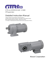
Note: If the fit is tight, you may use a jig such as the one shown here
to ease assembly. Sumitomo does not supply a mounting jig. This
information is provided for reference only.
Grease
Size
b c
Size
b c
A2 Bearing A2 Bearing
5Z 25 51104 1120 15 5110
4A/5A 25 51105 1220 13 5110
4B/5B 25 51105 1320 13 5110
4C/5C 25 51105 1420/30/40 15 51201
4D 35 51107 1520/21/22/30/31/40
HZ522/23/24 14 51202
4E 35 51107 1630/31/32/33/34/40
HA635 25 51204
4F 46 51109
Table 1. Jig Dimensions
Spacer b
Retaining Ring a
Ball
Bearing
c
Threaded Rod e Nut d
A2
Foot Mount - Mounting and Alignment
Mounting
• Consult Sumitomo when the unit will operate in conditions other than those specified above. Special unit
modifications may be required.
• Install the unit so inspection and/or maintenance procedures may be easily performed. Install all units that are not
shaft mounted on a sufficiently rigid base.
Foundations
Foundations must be designed to withstand shock and stress applied from the load side through the reducer.
Secure Housing
When the unit’s operating conditions include excessive vibration and/or frequent starts and stops, secure it on the
mounting surface by inserting dowel pins into the holes provided in the casing feet. This ensures that bending or
shearing forces are reduced on the mounting bolts. Be sure the dowel pins are inserted securely, especially when the
unit will be operated under severe, recurrent peak loads.
Accurate Alignment
When the reducer is connected to the motor and driven machine with couplings, the shafts must be properly aligned.
When the reducer is connected by V-pulleys or sprockets, ensure that the belts or chains are adjusted per manufacturers
recommendations.

6 Quick Start Guide Quick Start Guide 7
www.SumitomoDrive.com
3
Once driven shaft has been completely inserted into the unit’s keyed
hollow bore, secure the shaft in place using a keeper plate as shown
in this example, or some other means of securing the unit to the
driven shaft.
Do not operate unit until the torque arm has been
attached. Refer to the Torque Arm Installation section in
this guide for instructions.
1
Clean and degrease contact surfaces; reducer shaft and bore, and the
machine driven shaft.
Apply Molykote 321 or an equivalent dry film lubricant to the driven
shaft projection opposite from the shrink disc.
Do not apply any friction minimizing compound to the
driven shaft at or near the shrink disc.
2
Align the driven shaft with the bore of reducer/gearmotor bore and
carefully slide unit onto the driven shaft.
If the fit is tight, strike on the reducer hollow bore with a mallet to assist in
the assembly.
If using a soft non-metallic mallet during installation,
strike only against the unit’s steel hollow bore. Do not
strike the reducer housing or oil seal. Damage to the
bearings, the housing, and/or the seals may occur.
Note: If the fit is tight, use a jig such as the one shown in Table 1 to ease assembly. Sumitomo does not supply a
mounting jig. This information is provided for reference only.
Never tighten locking screws before shaft installation. Inner ring may become permanently contracted
even at low tightening torques.
Ensure that all power switches are locked out before installing or removing shrink disc.
Wear safety glasses and protective clothing at all times
Shrink Disc
Before placing unit onto driven shaft, do not apply grease, oil, or anti-seize grease to the entire driven
shaft or to the bore of the shrink disc. Use of these friction-minimizing products will adversely affect the
ability of the unit to transmit torque.
4
Set the (untightened) shrink disc on the reducer shaft.
3
Remove any wooden spacers that may have been used during shipping.
Lightly lubricate the hub outside diameter and shrink disc bore.
5
After confirming the correct position of the hub and shrink
discs, hand tighten three or four equally spaced locking
screws and ensure the discs are parallel. Hand-tighten
remaining locking screws.
6
Using a torque wrench, tighten the screws according to
the initial torque listed in Table 2. Tighten in either a
clockwise or counter-clock wise sequence, using ¼ turns,
until you can no longer complete a ¼ turn for any of the
screws. This procedure keeps the discs parallel.
7
Continue to tighten the screws for two more passes. This
compensates for system induced relaxing of the locking screws.
Degrease
these areas
Apply Molykote 321
to this shaft area only
7
6
5
4
3
2
1
8
Set the torque wrench to the final torque and tighten all locking screws. At this point, no screw should
turn; otherwise, set the torque wrench to the initial torque and repeat steps 6 and 7 above. It is not
necessary to re-torque after equipment has been in operation.

8 Quick Start Guide Quick Start Guide 9
www.SumitomoDrive.com
Taper-Grip® Bushing
Prior to installation of the gearbox onto the driven shaft, ensure that
the shaft length meets or exceeds the minimum shaft engagement
value “TT” detailed in Table 3.
Shaft Diameter
(in)
Tolerance
(in)
1-3/16 – 1-15/16 +0 / -0.0015
2 – 3-1/8 +0 / -0.0018
3-3/16 – 4-11/16 +0 / -0.0021
4-3/4 – 6-1/2 +0 / -0.0025
Reducer Size
BBB TT (in) TT (mm)
4A 7.8 198
4B 9.4 237
4C 11 279
4D 12.9 326
4E 14.2 359
4F 16.3 412
Reducer Size
HBB TT (in) TT (mm)
AA/Z 4.5 113
A 5 126
B 5.7 143
C 7.4 186
D 8.1 204
E 8.9 224
Shaft Diameter
(mm)
Tolerance
(μm)
(30 - 50) (+0 / -39)
(50 - 80) (+0 / -46)
(80 - 120) (+0 / -54)
(120 - 180) (+0 / -63)
Table 3. Driven Shaft Tolerance & Minimum Shaft Engagement
TT
Taper-Grip® Bushing
Socket Head Cap Screws
Thrust Collar
1
Remove bushing cover if unit was supplied with one.
2
Loosen socket head cap screws.
3
Remove (unscrew) Taper-Grip® bushing from the unit.
4
Clean all grease, oil and/or anti-seize grease from the driven shaft.
Failure to do so could result in damage to shaft.
Slide Taper-Grip® bushing onto driven shaft.
Clean Driven
Shaft
9
For units with a safety cover, reinstall the guard over the shrink disc.
Do not operate unit until the torque arm has been
attached. Refer to the Torque Arm Installation section
in this guide for instructions.
Screw Size M5 M6 M8 M10 M12 M16
Initial Torque (Nm) 5.1 12.4 31 63 105 263
Final Torque (Nm) 4.9 12 30 60 100 251
Socket Size (mm) 8 10 13 17 19 24
Table 2. Shrink Disc Size and Tightening Torque

10 Quick Start Guide Quick Start Guide 11
www.SumitomoDrive.com
5
Inspect and test Taper-Grip® bushing on shaft.
• Check shaft for burrs, corrosion, or warpage. Repair or
replace shaft as necessary.
• Slide bushing back and forth along shaft, checking for
surface irregularities and fit.
• Verify bushing is sized correctly for the shaft diameter.
6
Remove Taper-Grip® bushing from driven shaft.
7
Apply a thin layer of anti-seize grease to the male threads of the
Taper-Grip® bushing only.
Ensure that the anti-seize grease does not enter the Taper-
Grip® bushing bore.
Do not apply anti-seize grease to the female threads in the
hub.
Apply thin layer of
anti-seize grease to male
threads of bushing only.
Do not apply anti-seize grease
to the female threads in the
hub.
8
Screw Taper-Grip® bushing into the reducer leaving approximately
1 mm gap between the bushing flange and thrust collar.
Do not apply grease, oil, or anti-seize grease to the
driven shaft or the bushing bore before placing the unit
onto driven shaft. Use of these friction-minimizing products
will adversely affect the ability of the unit to transmit
torque.
CAUTION: The reducer must be externally supported prior
to insertion of driven shaft into bushing. External support
MUST be maintained until all bushing socket head cap
screws have been tightened to the appropriate
operational torque.
9
Mount or slide the reducer onto the driven shaft
Do not rock or pry the unit.
10
Screw Bolts into Taper-Grip® bushing.
• Lightly oil threads of each bolt before inserting.
• Finger tighten each bolt to secure in place.
• Be sure to maintain the 1 mm (approximate) gap
between the thrust collar and the bushing flange.
Feeler Gauge
Bushing
Flange
Thrust Collar

12 Quick Start Guide Quick Start Guide 13
www.SumitomoDrive.com
11
Tighten bushing bolts to the correct torque value.
• Following a star pattern, use a torque wrench to
gradually tighten each socket head cap screw in 20%
increments.
• Refer to Table 4, Taper-Grip® Bushing Bolt Tightening
Torques, for the correct operational screw torques.
14
For units that include a bushing safety cover, reinstall the guard over
the Taper-Grip® bushing.
Do not operate unit until the torque arm has been attached
to the unit and fixed to a rigid structure. The torque arm
prevents counter-rotation during unit operation. Refer
to torque arm installation section in this manual for
instructions.
13
After the reducer has been running for 20 to 30 hours, re-torque the
screws to the values in Table 2. Screw torques should be
subsequently checked at normal service intervals (i.e. every 6 months).
12
After installing and tightening the bushing bolts with a torque
wrench, apply grease or an anti-corrosion product to the exposed
portion of the shaft.
12
3
4
5
6
Table 4. Taper-Grip® Bushing Bolt Tightening Torques
Reducer
Size BBB
Screw Qty
x Size
Screw Torque
ft-lb (Nm)
4A 6 x M12 56 (75)
4B 6 x M12 104 (140)
4C 6 x M16 185 (250)
4D 6 x M16 223 (300)
4E 8 x M16 223 (300)
4F 10 x M16 223 (300)
Reducer
Size HBB
Screw Qty
x Size
Screw Torque
ft-lb (Nm)
AA/Z 6 x M10 23 31
A 6 x M12 38 51
B 6 x M12 38 51
C 6 x M16 94 128
D 6 x M16 148 200
E 8 x M16 148 200
Bolt Size Torque
ft-lb (Nm)
M16 155 - 165 210 - 225
M20 290 - 320 395 - 430
M24 510 - 555 690 - 755
M30 1020 - 1110 1380 - 1510
Apply grease to
exposed portion
of driven shaft
Item Description Item Description
1 Hex Nut 7 Lock Washer
2Lock Washer 8 Fulcrum Mounting Bracket
3 Threaded Extension Rod 9 Hex Bolt
4 Turnbuckle 10 Locking Nut (if supplied)
5 Threaded Arm 11 Locking Nut (if supplied)
6 Hex Nut 12 Hex Bolt
Table 5. Turnbuckle Type Torque Arm Parts Table 6. Bolt Tightening Torque
Note: [1] Bolt ISO/JIS Class 8.8
[1]
1
Attach the torque arm threaded extension rod to the bevel housing,
at the housing corner eyelet, using the appropriate nut, bolt and
lockwasher.
Insert the bolt through the brackets, torque arm sleeve (if supplied)
and reducer housing eyelet.
Place the lockwasher on the bolt and secure with nut per the torque
values given in Table 6.
Insert Bolt
Tighten Nut
1
3
4
2
5
67
8
9
1011
12
Turnbuckle Type Torque Arm
Turnbuckle Torque Arm
2
Install the turnbuckle onto the threaded extension rod (gearbox side)
and then threaded arm (foundation side) to the turnbuckle.
If the assembly was supplied with hex nuts to secure the turnbuckle,
install the nuts loosely, ensuring the left hand nut is used on the
threaded arm, prior to installing the turnbuckle and threaded arm.

14 Quick Start Guide Quick Start Guide 15
www.SumitomoDrive.com
3
Position the torque arm so
it will be in tension during
unit operation and mount
the fulcrum mounting
bracket to suitable
structure or foundation.
Mounting hardware for
fulcrum mounting bracket
are NOT supplied by
Sumitomo.
4
Position the torque arm as close as possible to 90° relative to the unit
output bore / driven equipment shaft.
Sumitomo does not recommend the use of multiple torque arm
assemblies to achieve a greater overall length.
Mounting
Bracket
Bolt
Threaded Arm
Lock Washer
Nut
5
Assemble the threaded arm to the fulcrum mounting bracket,
as shown. Some adjustment of the turnbuckle may be required
to lengthen or shorten the overall length. Secure it with the
appropriate nut, bolt and lockwasher.
• Insert the bolt through the brackets and threaded arm
eyelet.
• Place the lockwasher on the bolt and secure with nut per
the torque values given in Table 6.
6
If turnbuckle hex nuts were supplied, secure the turnbuckle position
by adjusting the previously installed turnbuckle nuts.
1
Assemble the torque arm mounting brackets or wishbone clevis to
the threaded arm, and attach the torque arm assembly to the bevel
housing, at the housing corner eyelet, using the pin and cotter pin.
Tighten mounting bolts according to the values listed in Table 8.
• Insert the clevis pin through the brackets and housing
eyelet.
• Insert the cotter pin into clevis pin and secure assembly.
Tie Rod Torque Arm
Item Description Item Description
1Flat Washer 7 Rubber Bushing
2 (2) Mounting Brackets or (1) Clevis 8 Washers
3 Hex Bolt 9 Lock Washer
4 Spacer 10 Clevis Pin
5 Threaded Arm 11 Cotter Pin
6 Hex Hut
123
56 6
7
8
4
2
4
9
10
11
Table 7. Tie Rod Type Torque Arm Parts
Tie Rod Type Torque Arm
Bolt Size Torque
ft-lb (Nm)
M16 155 - 165 210 - 225
M20 290 - 320 395 - 430
M24 510 - 555 690 - 755
M30 1020 - 1110 1380 - 1510
Table 8. Bolt Tightening Torque
Note: [1] Bolt ISO/JIS Class 8.8
[1]

16 Quick Start Guide Quick Start Guide 17
www.SumitomoDrive.com
2
Position the torque arm so it will be in tension during unit operation.
3
Position the torque arm as close as possible to 90° relative to the unit
output bore / driven equipment shaft.
Sumitomo does not recommend the use of multiple torque
arm assemblies to achieve a greater overall length.
4
After inserting the torque rod into the mounting surface, carefully
tighten nuts on either side of torque rod.
Do not over tighten nuts. Tighten to point where rubber
bushings can still be hand rotated when the unit is turned
off.
Before starting unit, verify the following:
• The torque arm will be in tension when the unit is in
operation.
• The torque arm is aligned with the reducer housing.
• The torque arm is perpendicular to the axis of the
output/driven shaft.
• The threaded arm is not touching the reducer housing.
Customer
Mounting
Surface
Bushing are free to
rotate by hand
CW LSS
Unit Rotation
Perpendicular to
output shaft axis Not perpendicular
Aligned with housing Not aligned with housing
Not perpendicular
Correct Incorrect
Ensure the torque arm has correct alignment and will be in tension during operation.

18 Quick Start Guide Quick Start Guide 19
www.SumitomoDrive.com
T-Type Torque Arm
3
Follow these steps to attach the mounting angle bracket:
• Place rubber bushing and mounting angle bracket on
the bolt.
• Verify that the mounting angle bracket hole is the correct
diameter for customer supplied bolt.
• Place remaining bushing, washer and two nuts on
the bolt.
Do not over-tighten nuts. Tighten to point where rubber
bushings can still be hand rotated.
2
Place washer and rubber bushing on bolt.
Insert torque arm bolt (supplied by customer) through mounting tab
on Banjo torque arm.
Make sure bolt is parallel to T-Type Torque Arm side
when fully installed.
1
Attach the T-Type Bracket to the reducer using the supplied
mounting hardware. Tighten mounting the bolts according to the
values listed in Table 9.
Torque Arm
Bracket
Mounting Bolts
Washer
Rubber Bushing
When installed,
bolt must be
parallel to this
surface
Washer
Rubber Bushings
Mounting Angle
Bracket
(Customer
Supplied)
Nuts
(Customer Supplied)
Bracket Tab Bore Typical Bolt Size [1]
Ø18 mm M16
Ø22 mm M20
Ø26 mm M24
Ø33 mm M24
Ø39 mm M36
Note [1] Bolt class should be greater or equal to ISO/JIS Class 8.8. Application
with multiple start/stops and/or shock loading should be 10.9 at a minimum.
Table 10. Recommended Bolt Size
Direct Mount Torque Arms in Tension
CW Shaft
Rotation
CCW Shaft
Rotation
CCW Shaft
Rotation
CW Shaft
Rotation
“Y1” Mounting
Position
“Y3” Mounting
Position
Table 9. Bolt Tightening Torque
Note: [1] Bolt ISO/JIS Class 8.8
Bolt Size Torque
ft-lb (Nm)
M16 155 - 165 210 - 225
M20 290 - 320 395 - 430
M24 510 - 555 690 - 755
M30 1020 - 1110 1380 - 1510
[1]

20 Quick Start Guide Quick Start Guide 21
www.SumitomoDrive.com
Banjo Type Torque Arm
3
Follow these steps to attach the torque arm to mounting structure or
mounting angle bracket (customer supplied):
• Verify that the mounting structure or mounting angle
bracket hole is the correct diameter.
• Place rubber bushing and mounting angle bracket on
bolt.
• Ensure the bolt passes through mounting structure or
mounting angle bracket hole.
• Place remaining bushing, washer and two nuts on the
bolt.
Do not over-tighten nuts. Tighten to point where
rubber bushings can still be hand rotated.
2
Place washer and rubber bushing on bolt. Insert torque arm bolt
(supplied by customer) through mounting tab on Flange Mount
(Banjo) type torque arm.
Make sure bolt is parallel to Flange Mount (Banjo) Type
torque arm surface when fully installed.
1
Attach the Flange Mount (Banjo) Torque Arm Bracket to the reducer
using mounting hardware.
Bracket
Mounting
Bolts(s)
Torque Arm
Bracket
When installed,
bolt must be
parallel to this
surface
Washer
Rubber
Bushing
T/A Bolt
(Customer
Supplied)
Mounting Angle
Bracket (Customer Supplied)
Washer
Rubber Bushings
Nuts
(Customer Supplied)
Top View
4
Confirm that the rubber bushings can still be rotated by hand. This
indicates the bushing has not been over-tightened.
Compressed bushings will not allow the bushings to properly absorb
the loads of the shaft mounted gearbox. This can lead to premature
failure.
Mounting angle bracket must be secured to the machine
structure.
5
Confirm the mounting angle bracket does not interfere with the
torque arm. There should be no metal-to-metal contact between
the two during a complete revolution of the driven equipment.
Metal-to-Metal contact between these two components
may lead to catastrophic failure of the reducer/gearmotor.
Bushings are
free to rotate by
hand
Table 11. Bolt Tightening Torque
Note: [1] Bolt ISO/JIS Class 8.8
Bolt Size Torque
ft-lb (Nm)
M16 155 - 165 210 - 225
M20 290 - 320 395 - 430
M24 510 - 555 690 - 755
M30 1020 - 1110 1380 - 1510
[1]

22 Quick Start Guide Quick Start Guide 23
www.SumitomoDrive.com
4
Confirm that the rubber bushings can still be rotated by hand. This
indicates the bushing has not been over-tightened.
Compressed bushings will not allow the bushings to
properly absorb the loads of the shaft mounted gearbox.
This can lead to premature failure.
If used, the mounting angle bracket must be secured to the
machine structure.
5
Confirm the mounting angle bracket does not interfere with the
torque arm. There should be no metal-to-metal contact between the
two during a complete revolution of the driven equipment.
Metal-to-Metal contact between these two components
may lead to catastrophic failure of the reducer/gearmotor.
Completed Assembly
Bushings are free to rotate by hand
Bracket Tab Bore Typical Bolt Size [1]
Ø18 mm M16
Ø22 mm M20
Ø26 mm M24
Ø33 mm M24
Ø39 mm M36
Note [1] Bolt class should be greater or equal to ISO/JIS Class 8.8. Application
with multiple start/stops and/or shock loading should be 10.9 at a minimum.
Table 12. Recommended Bolt Size Flange Mount
Motor
Mounting
Handle with care in order not to apply excessive force to the driven shaft or hollow shaft by twisting the reducer casing.
Reducer Supplied with Motor:
Some units may come from the factory with the motor attached. In this case, no additional preparation is required.
Quill Input Reducer (Non-Food Grade)
Reducer Supplied with Motor:
Quill Input Reducer (Food Grade)
Supplied without Motor:
Hollow input shaft units for the Food and Beverage industry have either an o-ring or a gasket for installation between
the motor and reducer.
Installation Instructions
1. Make sure that the o-ring is in the o-ring groove, or that the gasket is in place.
2. Apply a thin film of the supplied food-grade anti-seize paste to the hollow shaft. Save enough anti-seize
paste to coat the Cyclo output shaft.
• Inspect the shaft hollow bore and the motor shaft for debris or other material that may prevent the insertion
of the motor shaft into the hollow quill input shaft – carefully clean if necessary.
• To enable easy installation and removal of the motor, apply anti-seize paste to both the reducer hollow bore and the
motor shaft.
• Place the motor key into the motor shaft and carefully insert the motor into the quill high-speed shaft of the reducer.
• Ensure that the motor flange bolts are aligned with the through holes of the reducer flange, and also ensure that the
motor is properly aligned with the reducer.
• Bolt the motor into place. Refer to the motor operating instructions for proper bolt tightening torque.

24 Quick Start Guide Quick Start Guide 25
www.SumitomoDrive.com
Motor Wiring
The motor diagram found inside Sumitomo supplied motor conduit box cover is correct. If using a
motor manufactured by a company other than Sumitomo, please refer to that manufacturer’s instruction
manual for wiring, operating and maintenance details. When wiring motors into the power supply,
Sumitomo recommends the use of terminal rings to facilitate the connection.
• Protection for overloads, peak starting currents, short circuit currents and ground fault currents should be
in strict compliance with the National Electric Code (latest release) Article 430, local electrical codes and
building codes in order to minimize the possibility of personal injury, electrical shock, and fire.
• Disconnect the motor from the power supply and implement Lock Out/Tag Out procedures before
opening the motor conduit box and performing any motor maintenance.
• Do not handle the unit when cables are live.
Be sure to disconnect the power; otherwise electric shock may result.
• Ensure ambient is within manufacturer’s published ratings.
For Sumitomo TEFC motors, those are: -10 to 40°C, under 85% humidity, under 1000 meters altitude, free
of corrosive gases, explosive gases, vapors and dust.
• Keep all wiring and electrical parts dry and moisture free.
• Ensure the motor is installed in an area of unrestricted ventilation.
• Verify the power supply voltage and frequency values are within nameplate ratings:
voltage +/- 10%, frequency +/- 5%. The arithmetic sum of voltage and frequency variations should not
exceed 10%.
• Verify voltage imbalance between phases is no greater than 2%.
• Connect the power cabling to the motor according to the diagram inside the Sumitomo’s motor conduit
box cover or according the instructions supplied with another manufacturer’s motor; otherwise electric
shock or fire may result.
• Properly ground the motor: otherwise electric shock may result.
• The use of long power wiring can result in voltage drop.
Size power cabling to limit voltage drop to less than 2%.
• When wiring motors into the power supply, Sumitomo recommends the use of terminal rings to facilitate
the connection.
• After wiring the motor, check that the conduit box mounting and cover hardware is tight.
• For brake motors:
Ensure the brake coil rectifier is installed in an ambient less than 60°C.
Do not apply power continuously to the brake coil of a stopped brakemotor.
The brake coil will overheat, be damaged and may cause a fire.
• For single-phase motors, exercise caution so as not to damage the vinyl cover of the starting capacitor:
otherwise electrical shock may result.
Motor Protection
• Use a molded case circuit breaker for protection against short circuit.
• Use an overload protection device that protects the unit against voltage surges.
Lubrication
Inspection of Lubrication Method
• Caution: Before following the instructions below, read all lubrication stickers on the unit to
determine the lubrication type. Instructions listed on stickers supersede the instructions in this guide.
• Oil lubricated units are shipped without oil, unless the customer specified otherwise when the unit was
ordered. Always fill the unit with the correct type and quantity of lubricant prior to operation.
• Some oil-lubricated models may be shipped from the factory already filled to the correct level
with oil. A unit pre-lubricated with oil has a tag attached that identifies it as pre-filled. If a unit is pre-
lubricated with oil, no additional oil is needed. Before starting the unit, replace the oil fill plug with
the air breather shipped with the reducer.
• Models ordered without oil must be filled with lubricant before startup.
• Certain models must be filled with lubricant in two separate locations, the bevel or helical gear portion
(output) and the input portion.
• Grease lubricated models are filled with grease prior to shipping. Additional grease is not necessary.
• Consult the Operations and Maintenance Manual for additional lubrication information.
Oil Supply Procedures
• Always stop the unit before adding oil.
• Oil level may drop during operation, depending on the oil viscosity, temperature and direction of
rotation. Additional oil is not necessary. Check the oil level when the unit is stopped to ensure that it has
the correct amount of oil.
• It may take some time for the oil to settle when the oil viscosity is high.
• There may be two different oil fill locations for some combinations; refer to Oil Fill/Drain Locations.
• Consider implementing an oil analysis program to ensure lubricant continues to operate at peak
performance. Follow your lubrication provider’s oil analysis recommendations to ensure reducer
performance.
• Always consult factory and warehouses for overhaul of gearmotors and reducers. Familiarity with Cyclo®
products is necessary for proper overhaul.
• Do not overfill with oil! If overfilled, the unit’s operating temperature will rise too high and/or oil will
leak through the high speed shaft oil seal.
1. Remove the oil fill plug, as referenced in Oil Fill/Drain Locations.
2. Slowly add oil while checking the level through the oil bullseye, overfill plug, or gauge.
3. After the oil has settled, make sure the oil level is visible in the bulls eye, overfill plug, or upper red line of the Cyclo
oil level gauge.
4. Insert the oil fill plug after wrapping it with sealing compound or tape.

26 Quick Start Guide Quick Start Guide 27
www.SumitomoDrive.com
Recommended Oils
Oils that may be used to lubricate the Bevel Gear portion of the unit. These oils may also be used in the Cyclo®
portion if it is oil lubricated.
*VG68 is not available for ExxonMobil Spartan.
Gulf Oil:
ExxonMobil Oil:
Mobil Oil:
Total:
Kluber:
Idemitsu Oil:
BP Oil:
Shell Oil:
Caltex:
Castrol:
Food Grade Oil:
EP Lubricant HD
Spartan EP
Mobilgear 600XP
Carter EP
Kluberoil GEM1
Daphane Mechanic
Energol GR-XP
Omala S2 G
Meropa
Alpha SP
Klübersynth UH1 6-460
° F
14 32 50 68 86 104 122
° C
-10 0 10 20 30 40 50
ISO VG
68*
(14 °F to 41 °F)
100/150
(32 °F to 95 °F)
220/320/460
(86 °F to 122 °F)
Hyponic® and BBBH
Cyclo® 6000, HBB, BBB4 and BBB5
Hyponic® and BBBH speed reducers are grease lubricated as a standard. Consult factory for lubrication information for
non-standard oil lubricated units.
Table 13. Ambient Temperatures
Table 14. Recommended Oil Viscosity
• Use lubricants with low viscosity for operation during winter or at relatively low temperatures.
• Use lubricant with a viscosity within the range listed in Table 14, Recommended Oil Viscosity.
• Consult a local distributor, nearest authorized agent or Sumitomo directly when the unit will be operated in
ambient temperatures other than 14° to 104°F (-10° to 40°C). Special unit modifications may be necessary.
Minimum allowable viscosity 15 cSt (mm⁄) or more at
operating temperature
Viscosity that ensures oil film strength
adequate for load transmission
Maximum allowable viscosity 4300 cSt (mm⁄) max Viscosity that permits start-up of
BuddyBox®
Task Change Interval Conditions of Use
Supply of Oil At Installation All
Oil Change
First Change 500 hrs operation or 6 months,
whichever comes first. All
Second change and thereafter
2500 hrs operation or 6 months,
whichever comes first.
When case oil temperature is 158
° F
(70° C) or higher
5000 hrs operation or 1 year,
whichever comes first.
When case oil temperature is lower
than 158
° F (70° C)
Table 15. Oil Change Intervals
Ambient Temp. ISO Grade Recommended Oil
°F °C
32 to 95 0 to 35 460
Klübersynth UH1 6-460
Table 16. Recommended Food Grade Oil

28 Quick Start Guide Quick Start Guide 29
www.SumitomoDrive.com
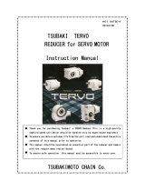
Cyclo®6000 Oil Fill Levels
Horizontal
Horizontal Flange Mount
Vertical
Vertical
Sizes 6130/5 and 6140/5 only
Cyclo® 6000 Oil Fill Quantities
Units: US liquid gallon (liter)Table 17. Approximate Oil Quantity
CHH = Cyclo Horizontal Foot Mounted
CHV = Cyclo Horizontal V-Flange Mounted
Note: Please consult factory for oil quantities
for when the reducer is mounted in any
other position or angle.
CVV = Cyclo Vertical V-Flange Mounted
CHF = Cyclo Horizontal Flange Mounted
Frame Size Mounting Configuration Frame Size
Mounting Configuration
CHH or CHV CVV CHF
CHH or CHV CVV CHF
6130, 6135 0.18 (0.68) 0.29 (1.1) 0.07 (.25) 6160DC, 6165DC 0.40 (1.5) 0.26 (1) 0.26 (1)
6140, 6145, 614H 0.18 (0.68) 0.29 (1.1) 0.07 (.25) 6170DC, 6175DC 0.63 (2.4) 0.5 (1.9) 0.53 (2.0)
6160, 6165, 616H 0.37 (1.4) 0.26 (1.0) 0.24 (0.9) 6180DB, 6185DB 0.92 (3.5) 0.53 (2.0) 0.61 (2.3)
6170, 6175 0.50 (1.9) 0.50 (1.9) 0.40 (1.5) 6190DA, 6195DA 1.5 (5.8) 0.71 (2.7) 1.0 (3.8)
6180, 6185 0.66 (2.5) 0.53 (2.0) 0.34 (1.3) 6190DB, 6195DB 1.6 (6.0) 0.71 (2.7) 1.1 (4.0)
6190, 6195 1.1 (4) 0.71 (2.7) 0.53 (2.0) 6205DA, 6205DB 1.6 (6.0) 2.9 (11) 1.1 (4.0)
6205 1.5 (5.5) 1.5 (5.7) 0.79 (3) 6215DA, 6215DB 2.6 (10) 3.7 (14) 1.5 (5.5)
6215 2.2 (8.5) 2.0 (7.5) 1.1 (4) 6225DA, 6225DB 2.9 (11) 4.8 (18) 1.6 (6.0)
6225 2.6 (10) 2.6 (10) 1.3 (5) 6235DA, 6235DB 4.5 (17) 6.1 (23) 2.5 (9.5)
6235 4.0 (15) 3.2 (12) 2.0 (7.5) 6245DA, 6245DB 4.8 (18) 7.7 (29) 2.6 (10)
6245 4.2 (16) 4.0 (15) 2.1 (8) 6255DA, 6255DB 6.1 (23) 11.1 (42) 3.4 (13)
6255 5.5 (21) 11.1 (42) 2.9 (11) 6265DA 8.5 (32) 13.5 (51) 4.5 (17)
6265 7.7 (29) 13.5 (51) 3.7 (14) 6275DA 15.9 (60) 15.9 (60)
6275 14.8 (56) 15.9 (60) 7.9 (30)

30 Quick Start Guide Quick Start Guide 31
www.SumitomoDrive.com
BBB4 and BBB5 in the Y4 Position
Sumitomo Cyclo® BBB4s are typically shipped from the factory without lubricating oil, unless the customer
specified otherwise when the unit was ordered.
The unit must contain the correct type and amount of lubrication before operating.
For all Y4 motor down mounting configurations, the Cyclo® portion is filled at the factory with grease. For
these units, the Cyclo® portion does not need to be filled with lubricant before start-up. The Bevel Gear
portion of models built for the Y4 mounting configuration still requires filling with gear oil before start-up.
Refer to the Lubrication Method section for details.
For the Cyclo® BBB4, BBB5 built for the Y4 mounting configuration and all HBB, the Cyclo® and the output
gear portions must be filled with lubricant separately and maintained separately. Lubricant does not flow
from one section to the other.
Separate
Lubrication
Bevel Gear Portion
Cyclo® Input Portion
Cyclo® BBB4 in Y4 Assembly
BBB4 Oil Quantities
Table 18. Single Reduction Approximate Oil Quantity
Units: US liquid gallon (liter) Note: Output = Bevel Gear Portion Input = Cyclo® Portion
Bevel Gear
Unit Size
Mounting Configuration
Output Input
4A10 0.43
(1.62)
0.84
(3.17)
0.30
(1.13) Grease
0.36
(1.36)
0.49
(1.84)
4A11 0.44
(1.66)
0.86
(3.26)
0.37
(1.40)
0.50
(1.88)
4A12 0.45
(1.71)
0.88
(3.35)
0.38
(1.45)
0.51
(1.93)
4A14 0.50
(1.91)
1.00
(3.77)
0.44
(1.65)
0.56
(2.13)
4B12 0.87
(3.29)
1.72
(6.50)
0.45
(1.72) Grease
0.88
(3.34)
0.85
(3.23)
4B14 0.92
(3.49)
1.84
(6.97)
0.94
(3.54)
0.91
(3.43)
4B16 1.04
(3.92)
2.01
(7.61)
1.05
(3.97)
1.02
(3.86)
4C14 1.46
(5.52)
2.94
(11.1)
0.72
(2.72) Grease
1.40
(5.30)
1.55
(5.88)
4C16 1.57
(5.96)
3.11
(11.8)
1.52
(5.74)
1.67
(6.32)
4C17 1.67
(6.34)
3.31
(12.5)
1.62
(6.12)
1.77
(6.70)
4D16 2.66
(10.1)
5.26
(19.9)
1.22
(4.61) Grease
2.56
(9.69)
2.76
(10.4)
4D17 2.75
(10.4)
5.41
(20.5)
2.65
(10.0)
2.85
(10.8)
4D18 2.83
(10.7)
5.54
(21.0)
2.72
(10.3)
2.93
(11.1)
4E17 3.85
(14.6)
7.60
(28.8)
1.65
(6.26) Grease
3.45
(13.1)
4.24
(16.1)
4E18 3.88
(14.7)
7.70
(29.1)
3.49
(13.2)
4.28
(16.2)
4E19 4.14
(15.7)
8.04
(30.4)
3.75
(14.2)
4.54
(17.2)
4F18 5.28
(20.0)
10.41
(39.4) 1.92
(7.28) Grease
4.89
(18.5)
5.65
(21.4)
4F19 5.50
(20.8)
10.74
(40.6)
5.10
(19.3)
5.86
(22.2)
Y1
Y1 Y3 Y2
Y4
Y5 Y6

32 Quick Start Guide Quick Start Guide 33
www.SumitomoDrive.com
Bevel Gear
Unit Size
Mounting Configuration
Output Input
4A10DA 0.44
(1.65)
0.84
(3.20)
0.30
(1.13) Grease
0.37
(1.39)
0.49
(1.87)
4A12DA 0.46
(1.74)
0.89
(3.38)
0.39
(1.48)
0.52
(1.96)
4A12DB 0.47
(1.78)
0.90
(3.43)
0.40
(1.52)
0.53
(2.00)
4B12DA 0.88
(3.32)
1.73
(6.53)
0.45
(1.72) Grease
0.89
(3.37)
0.86
(3.26)
4B12DB 0.89
(3.36)
1.73
(6.57)
0.90
(3.41)
0.87
(3.30)
4B14DA 0.93
(3.52)
1.85
(7.00)
0.94
(3.57)
0.91
(3.46)
4B14DB 0.94
(3.56)
1.86
(7.04)
0.95
(3.61)
0.92
(3.50)
4C14DA 1.47
(5.55)
2.95
(11.2)
0.72
(2.72) Grease
1.41
(5.33)
1.56
(5.91)
4C14DB 1.48
(5.59)
2.96
(11.2)
1.42
(5.37)
1.57
(5.95)
4C14DC 1.49
(5.64)
2.97
(11.3)
1.43
(5.42)
1.59
(6.00)
4C16DA 1.59
(6.03)
3.13
(11.8)
1.53
(5.81)
1.69
(5.39)
4C16DB 1.61
(6.08)
3.14
(11.9)
1.55
(5.86)
1.70
(6.44)
4C17DA 1.69
(6.41)
3.33
(12.6)
1.63
(6.19)
1.79
(6.77)
4D16DA 2.68
(10.1)
5.27
(20.0)
1.22
(4.61) Grease
2.58
(9.76)
2.77
(10.5)
4D16DB 2.69
(10.2)
5.29
(20.0)
2.59
(9.81)
2.79
(10.6)
4D17DB 2.78
(10.5)
5.44
(20.6)
2.68
(10.2)
2.88
(10.9)
4D17DC 2.82
(10.7)
5.48
(20.7)
2.72
(10.3)
2.91
(11.0)
4E17DA 3.86
(14.6)
7.62
(28.8)
1.65
(6.26) Grease
3.47
(13.1)
4.26
(16.1)
4E17DB 3.88
(14.7)
7.63
(28.9)
3.48
(13.2)
4.27
(16.2)
4E17DC 3.91
(14.8)
7.67
(29.0)
3.52
(13.3)
4.31
(16.3)
BBB4 Oil Quantities
Table 19. Double Reduction Approximate Oil Quantity
Units: US liquid gallon (liter) Note: Output = Bevel Gear Portion Input = Cyclo® Portion
Bevel Gear
Unit Size
Mounting Configuration
Output Input
4E18DA 3.9
(14.8)
7.7
(29.3)
1.7
(6.3) Grease
3.5
(13.3)
4.3
(16.3)
4E18DB 4.1
(15.7)
7.8
(29.6)
3.8
(14.2)
4.5
(17.2)
4E19DA 4.6
(17.5)
8.2
(31)
4.2
(16)
5
(19)
4E19DB 4.7
(17.7)
8.2
(31)
4.3
(16.2)
5.1
(19.2)
4F18DA 5.3
(20.1)
10.5
(39.6)
1.9
(7.3) Grease
4.9
(18.6)
5.7
(21.5)
4F18DB 5.5
(21)
10.5
(39.9)
5.2
(19.5)
5.9
(22.4)
4F19DA 6
(22.6)
10.9
(41.2)
5.6
(21.1)
6.3
(24)
4F19DB 6
(22.8)
10.9
(41.2)
5.6
(21.3)
6.4
(24.2)
BBB4 Oil Quantities
Table 19 Continued. Double Reduction Approximate Oil Quantity
Units: US liquid gallon (liter) Note: Output = Bevel Gear Portion Input = Cyclo® Portion
Y1 Y3 Y2
Y4
Y5 Y6 Y1 Y3 Y2
Y4
Y5 Y6

34 Quick Start Guide Quick Start Guide 35
www.SumitomoDrive.com
Bevel
Gear
Unit Size
Mounting Configuration
Output Input
5Z10 0.21 (0.80) 0.42 (1.58) 0.18
(0.67) Grease
0.17 (0.66) 0.24 (0.90)
5Z11 0.22 (0.85) 0.44 (1.65) 0.19 (0.71) 0.25 (0.95)
5Z12 0.25 (0.93) 0.47 (1.79) 0.21 (0.79) 0.27 (1.03)
5A11 0.42 (1.59) 0.81 (3.05) 0.22
(0.83) Grease
0.36 (1.35) 0.49 (1.85)
5A12 0.44 (1.68) 0.85 (3.23) 0.38 (1.44) 0.51 (1.94)
5A14 0.50 (1.90) 0.95 (3.58) 0.44 (1.66) 0.57 (2.16)
5B12 0.70 (2.66) 1.37 (5.17) 0.42
(1.60) Grease
0.60 (2.29) 0.81 (3.06)
5B14 0.76 (2.86) 1.46 (5.52) 0.66 (2.49) 0.86 (3.26)
5B16 0.88 (3.33) 1.63 (6.17) 0.78 (2.96) 0.99 (3.73)
5C14 1.41 (5.35) 2.84 (10.74) 0.93
(3.53) Grease
1.33 (5.05) 1.50 (5.66)
5C16 1.61 (6.08) 3.07 (11.62) 1.53 (5.78) 1.69 (6.39)
5C17 1.72 (6.52) 3.20 (12.13) 1.64 (6.22) 1.80 (6.83)
Y6
Y1 Y2
Y3
Y4
Y5
BBB5 Oil Fill Quantities
Table 20. Single Reduction Approximate Oil Quantity
Units: U.S. liquid gallon (liter) Note: Output = Bevel Gear Portion Input = Cyclo®
Table 21. Double Reduction Approximate Oil Quantity
Units: U.S. liquid gallon (liter) Note: Output = Bevel Gear Portion Input = Cyclo®
Bevel
Gear
Unit Size
Mounting Configuration
Output Input
5Z10DA 0.24 (0.89) 0.42 (1.60) 0.18
(0.70) Grease
0.24 (0.91) 0.26 (1.00)
5Z12DA 0.24 (0.89) 0.47 (1.78) 0.29 (1.10) 0.29 (1.10)
5Z12DB 0.26 (0.99) 0.47 (1.78) 0.29 (1.11) 0.29 (1.10)
5A12DA 0.44 (1.68) 0.85 (3.23) 0.22
(0.83) Grease 0.38 (1.44) 0.54 (2.04)
5A12DB 0.47 (1.78) 0.85 (3.23) 0.38 (1.44) 0.54 (2.04)
5B12DA 0.70 (2.66) 1.37 (5.17)
0.42
(1.60) Grease
0.63 (2.39) 0.83 (3.16)
5B12DB 0.73 (2.76) 1.39 (5.27) 0.63 (2.39) 0.83 (3.16)
5B14DA 0.76 (2.86) 1.46 (5.52) 0.68 (2.59) 0.89 (3.36)
5B14DB 0.78 (2.96) 1.46 (5.52) 0.68 (2.59) 0.89 (3.36)
5C14DA 1.44 (5.45) 2.86 (10.84)
0.93
(3.53) Grease
1.33 (5.05) 1.50 (5.66)
5C14DB 1.44 (5.45) 2.86 (10.84) 1.36 (5.15) 1.50 (5.66)
5C14DC 1.44 (5.45) 2.89 (10.94) 1.36 (5.15) 1.52 (5.76)
5C16DA 1.61 (6.08) 3.07 (11.62) 1.55 (5.88) 1.71 (6.49)
5C16DB 1.63 (6.18) 3.1 (11.72) 1.58 (5.98) 1.71 (6.49)
Y6
Y1 Y2
Y3
Y4
Y5
Y1
Y3
Y5 Y6
Y2
BBB4 and BBB5 Oil Fill/Drain Locations
Oil filler plug Oil level (Oil gauge) Oil drain plug Oil fill air vent
Y4
Grease

36 Quick Start Guide Quick Start Guide 37
www.SumitomoDrive.com
Helical
Buddybox
Size
Output Input
Y1 Y2 Y3 Y4 Y1 Y2 Y3 Y4
AA, Z
0.16 (0.60) 0.16 (0.60) 0.13 (0.49) 0.16 (0.60)
Grease
A
0.21 (0.80) 0.24 (0.91) 0.18 (0.68) 0.24 (0.91)
B
0.26 (0.98) 0.40 (1.51) 0.26 (0.98) 0.40 (1.51)
C
0.45 (1.70) 0.55 (2.10) 0.34 (1.30) 0.55 (2.10) 0.11 (0.40)
D
0.71 (2.70) 0.92 (3.50) 0.53 (2.00) 0.92 (3.50) 0.18 (0.68)
E
0.92 (3.50) 1.11 (4.20) 0.66 (2.50) 1.11 (4.20) 0.24 (0.90)
HBB Oil Fill Quantities
Table 22. Single Reduction Approximate Oil Quantity
Units: U.S. liquid gallon (liter) Note: Output = Bevel Gear Portion Input = Cyclo®
Start-Up
Check the following under no load prior to start-up:
• Be sure the Cyclo® reducer is filled with the correct amount of approved oil or grease.
• Ensure that the driven load and the Cyclo® reducer or gearmotor are properly secured.
• Verify the rotation direction of the electrical motor before connecting it to the load.
Motor rotation direction can be reversed by swapping any two of the motor power connections.
• Verify motor current imbalance does not exceed 10%.
• After unit comes up to speed, verify the motor current (average of all three motor leads) matches the motor
nameplate full load ampere rating +/- 10%.
• If after applying power to the motor, the unit will not come up to full speed, takes an unusually long time to come up
to full speed, or makes an abnormal sound, immediately disconnect the power and consult the factory.
• If possible, store indoors in an area that is clean and dry.
• Cover the motor completely with plastic or a weather-proof tarp.
• Allow for adequate ventilation to ward off the formation of condensation.
• If condensate plugs or drain plugs are installed, ensure they are functional.
• If the motor is equipped with a motor space heater, ensure it is properly connected and able to maintain the motor’s
interior temperature at least 5.6°C above ambient.
• Protect motor from flooding or exposure to harmful chemical vapors.
• Ensure storage area is free from vibration or lock motor shaft to prevent movement.
• Turning the motor’s rotor every month is recommended to redistribute the lubricant in the bearings.
• If condensation does occur, allow the motor to dry thoroughly before applying power.
• Test motor insulation resistance for a minimum value of 10 megaohms.
Long Term Storage Procedure
Caution: Consult the factory before operating units stored for periods longer than one year or for
additional details.*
Preparation for Six Months to One Year Storage
Operation After Six Months to One Year Storage
Preparation for electrical motor storage
Operation
After Six Months to One Year Storage
• Fill Shell VSI Circulating Oil 100 to 5% of required lubricating oil volume and tightly seal airflow opening (i.e., replace
breather with plug). For extended storage, Circulating Oil must be changed every year.
• Grease lubricated models are filled with grease prior to shipping and do not require additional lubricant during long
term storage.
• Operate the unit every 2 or 3 months after delivery by hand while ensuring a minimum of one and a half rotations of
the output shaft.
• Consult the factory for storage procedures if you plan to store your unit for longer than one year.
• Grease lubricated units do not require any special procedures following storage, however, you should follow the
steps listed in the Start-up section of this document before operating.
*For additional Long Term Storage Information, please refer to our Long Term Storage Procedure on our website.
For oil lubricated units:
~Completely drain the rust preventive or circulating oil from the unit.
~Flush the unit with the recommended operating oil.
~After flushing, fill the unit with the correct quantity of recommended oil.
~Follow the steps listed in the Start-up section of this document before operating.
Oil filler plug Oil level (Oil gauge) Oil drain plug
/