Page is loading ...

INSTALLATION INSTRUCTIONS
Page 1 of 10
JK/JL/JT Full Size Hiline Front Bumper (Wrangler JL (Excl. 4xE))
PART #JP-19537
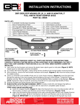
PARTS LIST:
1
Hiline Front Bumper
8
10mm Lock Washers
1
Bull Nose Hoop
4
10mm Hex Nuts
1
Skid Plate
2
10mm Double Nut Plates
2
Fog Light Brackets
8
8mm x 25mm Button Head Bolts
2
L-Brackets
10
8mm x 24mm OD x 2mm Flat Washers
1
Driver/Left Cube Light Bracket
8
8mm Lock Washers
1
Passenger/Right Cube Light Bracket
2
8mm Hex Nuts
1
Driver/Left JL/JT Skid Plate Bracket
8
6mm x 20mm Button Head Bolts
1
Passenger/Right JL/JT Skid Plate Bracket
2
6mm x 16mm Button Head Bolts
1
Driver/Left JK Skid Plate Bracket
18
6mm x 12mm OD x 1.6mm Flat Washers
1
Passenger/Right JK Skid Plate Bracket
2
6mm Lock Washers
1
License Pate Bracket
8
6mm Nylon Lock Nuts
2
License Plate Plugs
12
4mm x 15mm Button Head Bolts
2
Mesh Panels
20
4mm x 12mm OD x 1mm Flat Washers
4
12mm x 40mm Double Bolt Plates
12
4mm Lock Washers
8
12mm x 37mm OD x 3mm Flat Washers
8
4mm Hex Nuts
8
12mm Nylon Lock Nuts
2
30mm Plastic Caps
8
12mm Plastic Retainers
10
Wire Ties
2
10mm x 25mm Single Bolt Plates
1
6mm Hex Wrench
2
10mm x 35mm Button Head Bolts
1
5mm Hex Wrench
4
10mm x 30mm Hex Bolts
1
2.5mm Hex Wrench
10
10mm x 30mm OD x 3mm Flat Washers
1
4mm Hex Wrench
Skid Plate
(2) L-
Brackets
(2) License
Plugs
Bumper
Bull Nose Hoop
Passenger/Right
JL/JT Bracket
License Plate Bracket
Driver/Left
JL/JT Bracket
Passenger/Right
JK Bracket
Driver/Left
JK Bracket
Passenger/Right
Light Cube
Bracket
Driver/Left
Light Cube
Bracket
(2) Mesh
Panels

INSTALLATION INSTRUCTIONS
Page 2 of 10
PROCEDURE:
REMOVE CONTENTS FROM BOX. VERIFY ALL PARTS ARE PRESENT. READ INSTRUCTIONS
CAREFULLY BEFORE STARTING INSTALLATION. CUTTING MAY BE REQUIRED. ASSISTANCE IS
RECOMMENDED.
1. Start under the front bumper of the vehicle and remove the plastic lower splash guard or steel skid plate,
(Figure 1). NOTE: Splash guard or skid plate cannot be reinstalled.
2. Unplug the fog light wiring harness leading to the bumper, (Figure 2).
3. On JK models, remove the clips fastening the plastic fill panel to the top of frame behind the bumper. Slide
fill panel left or right to access bumper hardware from above, (Figure 3). NOTE: All models, bumper
mounting hardware will also be accessed from below.
4. With assistance, remove the front bumper, (Figures 4—7). Move the bumper to a stable surface. Remove
the fog lights and wiring harness. Depending on model and year, bumper may need to be disassembled to
remove fog lights and/or wire harness.
5. Factory fog lights Installation—determine fog light design first:
4-tab “JK” and “JL” standard fog light:
a. Select (1) Fog Light Bracket. Attach the Bracket to the factor fog light with (2) 4mm Button Head
bolts, (4) 4mm Flat Washers, (2) 4mm Lock Washers and (2) 4mm Hex Nuts, (Figure 8).
b. Select (2) 4mm Clip Nuts. Attach the Clip Nuts to the outer mounting plate on the back of the right
side of the Bumper, (Figure 9).
c. Attach the Passenger/Right fog light assembly to the mounting location with (4) 4mm Button Head
Bolts, (2) 4mm Lock Washers and (4) 4mm Flat Washers, (Figures 9 & 10). IMPORTANT: Do not
overtighten fog light hardware or damage to the fog light may result.
d. Repeat previous Steps to attach the Driver/Left fog light.
3-screw 2018-on “JL” Sport with 1pc plastic outer bumper cover & halogen fog light:
a. Remove the driver/left fog light assembly, (Figure 11).
b. Attach the Passenger/Right fog light assembly to the inner mounting tab with (2) 4mm Button Head
Bolts, (2) 4mm Lock Washers and (2) 4mm Flat Washers, (Figure 12).
c. Attach the fog light to the outer mounting tab with (1) 4mm Button Head Bolt, (2) 4mm Flat
Washers, (1) 4mm Lock Washer and (1) 4mm Hex nut, (Figure 12). IMPORTANT: Do not
overtighten fog light hardware or damage to the fog light may result. NOTE: No Adapter Brackets
required.
d. Repeat previous Steps to attach the Driver/Left fog light.
6. Install factory fog light wiring harness into back of Bumper.
7. For Bull Nose Hoop installation:
a. Determine if a lightbar will be attached to the top off the Hoop, (lightbar not included). If no light will
be installed, proceed to step 7e.
b. Select (1) L-Bracket. Attach the L-Bracket to the top of the Hoop with (1) 6mm x 20mm Button Head
Bolt, (2) 6mm Flat Washers and (1) 6mm Nylon Lock Nut, (Figure 13). Do not tighten hardware.
c. Repeat previous Step to attach (1) L-Bracket to the Passenger/Right side of the Hoop.
d. Attach a lightbar, (not included), to the (2) L-Brackets with (2) 6mm x 16mm Button Head Bolts, (1)
6mm Lock Washer and (1) 6mm Flat Washer, (Figure 13).
e. Attach the Bull Nose Hoop to the top of the Bumper with (4) 10mm x 30mm Hex Bolts, (4) 10mm
Lock Washers, (4) 10mm Flat Washers and (2) 10mm Double Nut Plates, (Figure 15).
f. Center and level the Bull Nose Hoop and tighten Hoop hardware.
8. Determine if Cube Lights will be installed (Lights not included):
For Mesh Panel installation:
a. Select (1) Mesh Panel.
b. Attach the Mesh Panel to the (2) mounting tabs on the Passenger/Right back of the wing of the
Bumper with (2) 6mm x 20mm Button Head Bolts, (2) 6mm Flat Washers and (2) 6mm Nylon Lock
Nuts, (Figure 14).
c. Repeat the previous Steps to attach (1) Mesh Panel to the Driver/Left side of the Bumper.

INSTALLATION INSTRUCTIONS
Page 3 of 10
For Cube Light installation, (Lights not included):
a. Locate the mounting tab above the outer square holes.
b. Attach (1) Cube Light to the mounting tab on the Passenger/Right side of the Bumper.
c. Follow the manufacturers instructions to wire the Light.
d. Repeat previous Steps for the Driver/Left side of the Bumper.
9. Select (2) 12mm Double Bolt Plates. Insert the Plates into the slots in the Passenger/Right mounting plate
on the back of the Bumper. Thread (4) 12mm Plastic Retainers onto the Plate to hold it in place, (Figure
15). Repeat this Step to attach (2) 12mm Double Bolt Plates to the Driver/Left mounting plate.
10. With assistance, hold the Bumper Assembly up to the frame and align the Double Bolt Plates to the
mounting holes on the frame. Using block or jack stands, temporarily support the weight of the Bumper.
WARNING: To avoid possible injury or damage to the vehicle, do not proceed until the Bumper is fully and
safely supported. Attach the Double Bolt Plates to the end of the frame with (8) 12mm Flat Washers and
(8) 12mm Nylon Lock Nuts, (Figures 16 & 17). Do not fully tighten hardware.
11. Winch Installation, (winch not included).
a. Attach the winch to the top of the mounting plate on top of the Bumper, (Figure 18).
b. Follow the manufacturer’s instructions to properly attach the winch to the top of the bumper and
to connect the winch to the electrical system. NOTE: As per winch instructions, never wind rope
over top of the winch drum.
12. Select the License Plate Bracket. Attach the Bracket to the bottom of the bumper using (2) 6mm Button
Bolts, (4) 6mm Flat Washers and (2) 6mm Nylon Lock Nuts, (Figure 19). Use the provided (2) Plastic
Plugs to attach the License Plate to the front of the Bracket, (Figure 20).
13. Reattach the wiring harness to the fog lights. Reinstall electric sway bar if equipped.
14. Level and adjust Bumper, then tighten all hardware.
15. For JK models:
a. Select the Driver/Left JK Skid Plate Bracket.
b. Attach the Bracket to the outer hole in the back of the crossbar on the bottom of the frame with (1)
8mm Bolt Plate, (1) 8mm Flat Washer, (1) 8mm Lock Washer and (1) 8mm Hex Nut, (Figures
21—23). Repeat this Step to attach the Passenger/Right JK Skid Plate Bracket.
c. Select the Skid Plate.
d. Attach the Skid Plate to the back lower rear of the Bumper with (6) 8mm Button Head Bolts, (6)
8mm Lock Washers and (6) 8mm Flat Washers, (Figure 26).
e. Attach the Skid Plate to the Skid Plate Brackets with (2) 8mm Button Head Bolts, (4) 8mm Flat
Washers, (2) 8mm Lock Washers and (2) 8mm Hex Nuts, (Figure 27).
For JL/JT models:
a. Select (1) 10mm Bolt Plate.
b. Insert the Bolt Plate up into the frame and out the second from the bottom hole towards the center
of the vehicle, (Figure 24).
c. Attach the Driver/Left JL/JT Skid Plate Bracket to the Bolt Plate with (1) 10mm Flat Washer, (1)
10mm Lock Washer and (1) 10mm Hex Nut, (Figure 25).
d. Select the Skid Plate.
e. Attach the Skid Plate to the back lower rear of the Bumper with (6) 8mm Button Head Bolts, (6)
8mm Lock Washers and (6) 8mm Flat Washers, (Figure 26).
f. Attach the Skid Plate to the Skid Plate Brackets with (2) 8mm Button Head Bolts, (4) 8mm Flat
Washers, (2) 8mm Lock Washers and (2) 8mm Hex Nuts, (Figure 27).
16. Stand back from the vehicle and check to see that the Skid Plate is centered and level on the vehicle and
adjust as required. Once properly aligned, fully tighten all hardware.
17. Do periodic inspections of the installation to make sure that all hardware is secure and tight.
To protect your investment, Do not use any type of polish or wax that may contain abrasives that could damage the
finish. Mild soap may be used to clean the Front Bumper and Skid Plate.

INSTALLATION INSTRUCTIONS
Page 4 of 10
(Fig 4) Remove front bumper assembly (JK
passenger side inner bumper bolts pictured)
(Fig 2) Unplug the wiring harness leading to the
front bumper (arrow-JL passenger side pictured)
(Fig 3) JK models-Remove clips attaching fill
panel to top of frame. Slide panel left or right
to access bumper bolts from above
Front
(Fig 1) Remove plastic splash guard
or skid plate from bottom of bumper
Front
Front

INSTALLATION INSTRUCTIONS
Page 5 of 10
(Fig 7) Front Bumper and splash guard
removed (2020 Gladiator JT shown)
(Fig 5) Front Bumper and splash guard
removed from vehicle (07-18 JK pictured)
Front
(Fig 6) Remove front bumper and splash
guard or skid plate (2018-on JL pictured)
(Fig 8) Attach the factory fog
light to (1) Fog Light Bracket
(2) 4mm Screws
(4) 4mm Flat Washers
(2) 4mm Lock Washers
(2) 4mm Hex Nuts

INSTALLATION INSTRUCTIONS
Page 6 of 10
(Fig 11) 2018-on Sport model with
1pc plastic bumper cover. Driver/left
Fog light assembly pictured
(Fig 9) Attach the factory fog light to the mounting
location (4 pin fog light mounting shown)
(Fig 12) Attach 2018-on Sport model fog light
assembly to mounting plates, no adapters
required. Passenger/Right Bumper illustrated
Front
Front
4mm Button Head Bolt
(2) 4mm Flat Washer
4mm Lock Washer
4mm Hex Nut
(2) 4mm Bolts
(2) 4mm Lock Washers
(2) 4mm Flat Washers
(2) 4mm Bolts
(4) 4mm Flat Washers
(2) 4mm Lock Washers
(2) 4mm Hex Nuts
(Fig 10) Factory fog light attached to the back
of the Bumper (4 pin fog light mounting shown)
(2) 4mm Button Head Bolts
(2) 4mm Lock Washers
(2) 4mm Flat Washers

INSTALLATION INSTRUCTIONS
Page 7 of 10
(Fig 16) Thread (2) 12mm Plastic Retainers
onto the (4) 12mm Double Bolt Plates to
hold them in place. Attach the Bumper to
the Passenger/Right Mounting Plate
(4) 12mm Plastic Retainers
(4) 12mm Flat Washers
(4) 12mm Hex Nuts
Front
(Fig 13) Attach (1) L-Bracket to
the top of the Bull Nose Hoop
(Fig 15) Attach the Bull Nose
Hoop to the top of the Bumper
6mm x 16mm Button Head Bolt
6mm Lock Washer
6mm Flat Washer
6mm x 20mm Button Head Bolt
(2) 6mm Flat Washers
6mm Lock Washer
6mm Hex Nut
(2) 10mm x 30mm Hex Bolts
(2) 10mm Lock Washers
(2) 10mm Flat Washers
10mm Double Nut Plate
(Fig 14) Attach (1) Mesh Panel
to the back of the Bumper
(2) 6mm x 20mm Button Head Bolts
(4) 6mm Flat Washers
(2) 6mm Nylon Lock Nuts

INSTALLATION INSTRUCTIONS
Page 8 of 10
(Fig 18) Attach winch (not included) to the
mounting plate on the back of the Bumper
Front
(Fig 19) Attach the License Plate
Bracket to the front of the Bumper
(2) 6mm x 20mm Button Bolts
(4) 6mm Flat Washers
(2) 6mm Nylon Lock Nuts
Front
(Fig 20) Insert the (2) License Plate
Plugs into the License Plate Bracket
Front
(Fig 17) Bumper attached to the
Passenger/Right mounting plate
Front

INSTALLATION INSTRUCTIONS
Page 9 of 10
Front
(Fig 21) For JK models, locate the
outer hole in the back of the crossbar
(Fig 23) For JK models, attach
(1) JK L-Bracket to the crossbar
10mm Button Head Bolt
(2) 10mm Flat Washers
10mm Lock Washer
10mm Hex Nut
(Fig 22) (1) 8mm Bolt Plate inserted into
the crossbar (Passenger/Right shown)

INSTALLATION INSTRUCTIONS
Page 10 of 10
(Fig 24) For JL and JT models, insert
(1) 8mm Bolt Nut Plate into the bottom
of the frame and out the hole shown
(Fig 25) For JL and JT models,
attach the Driver/Left Skid Plate
Bracket to the 8mm Bolt/Nut Plate
(Fig 26) Attach the top of the Skid
Plate to the lower rear of the Bumper
(Fig 27) Attach the bottom of the Skid
Plate to the Skid Plate Brackets,
(JL/JT model installation shown)
10mm Bolt Plate
10mm Flat Washer
10mm Lock Washer
10mm Hex Nut
(6) 8mm Button Head Bolts
(6) 8mm Lock Washers
(6) 8mm Flat Washers
8mm Button Head Bolt
(2) 8mm Flat Washers
8mm Lock Washer
8mm Hex Nut
/