Page is loading ...

VDO Face 5 Video Panel
User Manual
™

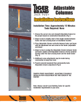
Dimensions
All dimensions are in millimeters
110
86
500
453
562.5
542
M10
Information subject to change without notice. HARMAN Professional Denmark ApS disclaims liability for any injury, damage, direct or indirect loss,
consequential or economic loss or any other loss occasioned by the use of, inability to use or reliance on the information contained in this document.
©2010-2018 HARMAN Professional Denmark ApS. All rights reserved. Martin® is a trademark of HARMAN Professional Denmark ApS registered in the
United States and/or other countries. Features, specifications and appearance are subject to change without notice.
HARMAN Professional Denmark ApS - Olof Palmes Allé 18 - 8200 Aarhus N - Denmark
www.martin.com
VDO Face 5™ User Manual: P/N 5079793 Rev. C

3
541
All dimensions are in millimeters
50
555
VDO Face 5 Single Header
499
96
84
68
VDO Face 5 Double Header
VDO Face 5 Curving Header
68
68
96
86
Ø25

4 VDO Face 5™ user manual
All dimensions are in millimeters
VDO Face 5 Panel Clamp
50
[0

5
Base unit and stabilizer leg
90
All dimensions are in millimeters
240
465
1124
800
90
998
Adjustable
240
500
20 - 40 mm
170
182
VDO Face Footer floor stand system
Panel mount ladder

6 VDO Face 5™ user manual
Safety Information
The following symbols are used to identify important safety information on the product and in this manual:
This product is for professional use only. It is not for household use.
This product presents risks of severe injury or death due to fire hazards, electric shock and falls.
A revised version of this user manual will become available each time we can improve the quality of the
information we provide in it. Please check that you have the latest revision of the user manual for this
product before installing, operating or servicing the product. Martin® user manual revisions are identified at
the bottom of page 2. You can download the latest user documentation from the product’s Product Support
/ Tech Docs page on the Martin® website at www.martin.com.
The instructions and safety limits given in this user manual are provided to make sure that installers
comply with the safety standards that apply to stage and studio environments. Follow these
instructions carefully and do not exceed the limits given, or you may create an installation that is
dangerous and does not meet required safety standards. Observe all locally applicable laws,
regulations and codes regarding the safety of permanent and temporary structures, installations
and electrical systems.
Read this manual before installing, powering, operating or servicing this product, follow the safety
precautions listed below and observe all warnings given in this manual and printed on the product.
If you have questions about how to install or operate the VDO Face 5™ system safely, please contact your
Martin supplier or call the Martin 24-hour service hotline on +45 8740 0000, or in the USA on
1-888-tech-180.
PROTECTION FROM ELECTRIC SHOCK
• Connect the product to AC mains power within the range 100-240 V nominal at 50 or 60 Hz only.
• Disconnect the entire installation from power and ensure that power cannot be reconnected, even
accidentally, before carrying out any installation or maintenance work.
• Disconnect the product from power when not in use.
• Always ground (earth) the product electrically.
• Use only a source of power that complies with local building and electrical codes. Power distribution
circuits must be fitted with an overcurrent fuse or circuit breaker with a maximum rated current of 20 A and
ground-fault (earth-fault) protection of high breaking capacity (≥1500 A).
• Make power connections between VDO Face 5™ panels using only the cables supplied by Martin for this
purpose.
• Protect power connections from water and rain.
WARNING!
Read the safety precautions in this section before
installing, powering, operating or servicing VDO
Face 5™ products.
Warning!
Safety hazard.
Risk of severe
injury or death.
Warning!
Refer to
manual before
installing,
powering or
servicing.
Warning!
Hazardous
voltage. Risk of
lethal or severe
electric shock.
Warning!
Hot surface. Do
not touch.
Warning!
Fire hazard.
Warning!
Emission
hazardous to
eyesight.

Safety Information 7
• Keep the attached rubber caps installed on any unused power and data connectors at all times. Reinstall
caps over connectors as soon as a video wall is disassembled.
• Connect a VDO Face 5™ installation to power using only 20 amp-rated industrial Type B power plugs and
socket outlets that comply with IEC 60309 (or a comparable national standard) and provide an electrical
connection to ground (protective earth).
• When using AC mains power at 100-120 V, connect a maximum of ten (10) VDO Face 5™ panels in total
to AC power in one chain using the power IN and OUT connectors in the back of the panels. When using
AC mains power at 200-240 V, connect a maximum of twenty (20) VDO Face 5™ panels in total to AC
power in one chain using the power IN and OUT connectors in the back of the panels.
• Before using the product, check that all power distribution equipment and cables are in perfect condition
and rated for the current requirements of all connected devices.
• Do not use the product if the panel, a power cable, a power connector or a seal around a multi-connector
in the back of a panel is in any way damaged, defective or showing signs of overheating.
• Do not attempt to open the product.
• Refer any service operation not described in this manual to an authorized Martin® service agent.
PROTECTION FROM FIRE AND BURNS
• Provide a minimum clearance of 10 cm (4 in.) around the front and back of the panel.
• Ensure good ventilation around the panel, controller, power supply and all other devices in the installation.
• Do not stick filters, masks or other materials directly onto LED modules.
• Do not modify the product in any way not described in this manual.
• Install only genuine Martin parts and parts described in this manual in or on the product.
• Do not operate the product if the ambient temperature (T
a
) exceeds 45° C (113° F).
• The cover on the back of the product can become hot, up to 72° C (162° F) if running constantly at full
intensity, full white. Avoid accidental skin contact.
PROTECTION FROM INJURY
• Do not install VDO Face 5™ panels using any other method or any other equipment than those described
in this manual.
• Make sure that any structure used for support can hold at least ten (10) times the weight of all the items it
supports.
• Check that all panels, rigging hardware and other elements in the installation are securely fastened and
cannot fall, causing injury or damage.
• Block access below and around the work area and work from a stable platform whenever installing,
servicing or moving items in the installation.
• Do not look at lit LEDs from a distance of less than 1 m (3 ft. 4 in.) without suitable protective eyewear.
• Be prepared for panels to light up suddenly if they receive a video signal.
• Do not view lit LEDs with optical instruments that may concentrate the light output.
PROTECTION FROM INJURY CAUSED BY WIND PRESSURE
Wind can create a risk of serious or lethal injury and damage due to falling panels. In any location where an
array of VDO Face 5™ panels may be exposed to wind pressure or other air currents, take the following
precautions:
• Support panels using a structure that is capable of holding the panels securely without any safety risk
when panels are exposed to wind pressure.
• Secure panels against any swinging, snaking or other lateral movement that might occur when panels are
exposed to wind pressure. Fasten panels to anchoring points as directed in this user manual.
• Ensure that professional technicians constantly monitor weather forecasts and local wind speed at the
installation site. Technicians must remove all panels from the installation immediately in the following
situations:
- In flying installations where VDO Face 5™ panels are suspended from VDO Face Headers, remove all
panels from the installation immediately if constant or gusting wind speed that exceeds Force 8
Beaufort, 20 m/s or 45 mph is forecast for, or present at, the installation location.
- In standing installations where VDO Face 5™ panels are supported on VDO Face Footer floor stands,
remove all panels from the installation immediately if constant or gusting wind speed that exceeds
Force 2 Beaufort, 3 m/s or 7 mph is forecast for, or present at, the installation location.

8 VDO Face 5™ user manual
SAFETY PRECAUTIONS FOR FLYING INSTALLATIONS
Respect the following precautions when installing an array of panels hanging from the Face Header
suspension system:
• Respect the maximum limits given in this user manual for the number of panels that you can suspend
vertically. The maximum limit varies depending on installation type. Make sure that you respect the limit
that applies in the installation concerned.
• Make sure that each separate item of rigging hardware (chain, cable, shackle, etc.) can hold at least ten
(10) times the total weight of the header, panels, hardware, cables etc. that are suspended under that
item. For example, if a header and all the panels, hardware, cables etc. hanging from it weigh 100 kg in
total, each item that is used to suspend that 100 kg load must be capable of supporting 1000
kg. This
requirement applies to single and double headers. The requirement also applies regardless of whether a
header is supported by one, two or three chains or cables: if the 100 kg load in the example above is
suspended from three chains, then each chain must be capable of supporting 1000 kg.
• Make sure that each eyebolt that is used to suspend or secure a column of panels is fastened to the
supporting structure with its own cable or chain. Do not loop one cable or one chain through more than
one eyebolt.
• Start by installing headers. Then install panels at the top and work downwards.
• Do not suspend VDO Face 5™ panels at any other angle than hanging vertically downward.
• Make sure that there is no slack in any item of rigging hardware: all cables, chains, etc. used for
suspension must be equally tight.
• Disassemble a suspended installation by removing panels at the bottom and working upwards. Do not
remove headers until all panels have been removed.
SAFETY PRECAUTIONS FOR STACKED INSTALLATIONS
Respect the following precautions when creating a free-standing array of panels using the Face Footer floor
stand system:
• Respect the limits given in the ‘Physical installation’ chapter of this user manual for the number of VDO
Face 5™ panels that you may install in a vertical column and the minimum weight of ballast that you must
fasten to each stabilizer leg. These limits vary depending on installation type. Make sure that you respect
the limits that apply in the installation concerned.
• Start by installing base units and adjust level if necessary, then install stabilizer legs, ballast and panel
support ladders. FInally, install panels.
• Do not stack panels using the VDO Face Footer system at any other angle than standing vertically.
• Do not install items weighing more than 90 kg (199 lbs.) on a Face Footer floor stand base unit. This
means that you must not install more than eight (8) Martin® VDO Face 5™ video panels and the fastening
hardware described in this user manual in a vertical column on one Face Footer floor stand.
• Fasten at least one stabilizer leg to the outside end of each base unit at the edges of a Face Footer
installation.
• Fasten at least one stabilizer leg to every base unit in the installation.
• When adjusting the feet of Face Footer floor stand elements to make sure that they are horizontally level,
check that no more than 20
mm (0.8 in.) of threaded shaft is visible between the adjustment nut on each
foot and the locknut on the foot’s threaded shaft. Readjust the feet on all the elements or, if necessary,
add supporting plates under the feet that are strong enough and stable enough to safely support the load
that will be placed on them.
• Do not install panels on the Face Footer system before you have fastened all required ballast to the
stabilizer legs.
• Make sure that any ballast that is fastened to stabilizer legs cannot be removed while panels are installed
on the Face Footer system.
• Install VDO Face video panels on the Face Footer system only if the installation is located on a stable
surface that is capable of safely supporting the total load placed upon it and if the installation will not be
subject to shock, vibration or any other movement.
• Do not create an array using the Face Footer system that consists of only a single column of VDO Face
5™ panels. Install a minimum of two columns of VDO Face 5™ panels with base units and panels
securely fastened to each other side-by-side as described in this user manual.
• Do not climb on or rest ladders against an installation that uses the Face Footer system.
• Do not move or transport the Face Footer system with panels installed. Remove panels before moving or
transporting base units and stabilizer legs.
• When you tear down an array of video panels, do not remove any ballast from Face Footer stabilizer legs
until all panels have been removed from the installation.
• Disassemble a stacked installation by removing panels at the top and working downwards.

Contents
Safety Information. . . . . . . . . . . . . . . . . . . . . . . . . . . . . . . . . . . . . . . . . . . . . . . . . . . . . . . . . . . . . . . . . . 6
Introduction . . . . . . . . . . . . . . . . . . . . . . . . . . . . . . . . . . . . . . . . . . . . . . . . . . . . . . . . . . . . . . . . . . . . . . . 10
Panels and flightcases. . . . . . . . . . . . . . . . . . . . . . . . . . . . . . . . . . . . . . . . . . . . . . . . . . . . . . . . . . . . . . 10
Avoiding damage to panels . . . . . . . . . . . . . . . . . . . . . . . . . . . . . . . . . . . . . . . . . . . . . . . . . . . . . . . . . . 11
Using for the first time . . . . . . . . . . . . . . . . . . . . . . . . . . . . . . . . . . . . . . . . . . . . . . . . . . . . . . . . . . . . . . 11
Overview . . . . . . . . . . . . . . . . . . . . . . . . . . . . . . . . . . . . . . . . . . . . . . . . . . . . . . . . . . . . . . . . . . . . . . . . . 12
Physical installation . . . . . . . . . . . . . . . . . . . . . . . . . . . . . . . . . . . . . . . . . . . . . . . . . . . . . . . . . . . . . . . 13
Installing single panels on a truss or structure. . . . . . . . . . . . . . . . . . . . . . . . . . . . . . . . . . . . . . . . . . . . 14
Stacking panels on floor stands. . . . . . . . . . . . . . . . . . . . . . . . . . . . . . . . . . . . . . . . . . . . . . . . . . . . . . . 15
Flying panels in a flat array . . . . . . . . . . . . . . . . . . . . . . . . . . . . . . . . . . . . . . . . . . . . . . . . . . . . . . . . . . 23
Flying panels in a curved array . . . . . . . . . . . . . . . . . . . . . . . . . . . . . . . . . . . . . . . . . . . . . . . . . . . . . . . 36
Dismantling a flying installation . . . . . . . . . . . . . . . . . . . . . . . . . . . . . . . . . . . . . . . . . . . . . . . . . . . . . . . 39
AC power . . . . . . . . . . . . . . . . . . . . . . . . . . . . . . . . . . . . . . . . . . . . . . . . . . . . . . . . . . . . . . . . . . . . . . . . . 40
Power connections . . . . . . . . . . . . . . . . . . . . . . . . . . . . . . . . . . . . . . . . . . . . . . . . . . . . . . . . . . . . . . . . 40
Inrush current and earth leakage. . . . . . . . . . . . . . . . . . . . . . . . . . . . . . . . . . . . . . . . . . . . . . . . . . . . . . 41
Fuses . . . . . . . . . . . . . . . . . . . . . . . . . . . . . . . . . . . . . . . . . . . . . . . . . . . . . . . . . . . . . . . . . . . . . . . . . . . 42
P3 communication link . . . . . . . . . . . . . . . . . . . . . . . . . . . . . . . . . . . . . . . . . . . . . . . . . . . . . . . . . . . . 43
Planning the P3 link . . . . . . . . . . . . . . . . . . . . . . . . . . . . . . . . . . . . . . . . . . . . . . . . . . . . . . . . . . . . . . . . 43
Connecting the P3 link. . . . . . . . . . . . . . . . . . . . . . . . . . . . . . . . . . . . . . . . . . . . . . . . . . . . . . . . . . . . . . 44
Operation . . . . . . . . . . . . . . . . . . . . . . . . . . . . . . . . . . . . . . . . . . . . . . . . . . . . . . . . . . . . . . . . . . . . . . . . . 45
Monitoring status and testing. . . . . . . . . . . . . . . . . . . . . . . . . . . . . . . . . . . . . . . . . . . . . . . . . . . . . . . . . 45
Service and maintenance. . . . . . . . . . . . . . . . . . . . . . . . . . . . . . . . . . . . . . . . . . . . . . . . . . . . . . . . . . 46
Storage . . . . . . . . . . . . . . . . . . . . . . . . . . . . . . . . . . . . . . . . . . . . . . . . . . . . . . . . . . . . . . . . . . . . . . . . . 46
Cleaning. . . . . . . . . . . . . . . . . . . . . . . . . . . . . . . . . . . . . . . . . . . . . . . . . . . . . . . . . . . . . . . . . . . . . . . . . 46
Installing new software . . . . . . . . . . . . . . . . . . . . . . . . . . . . . . . . . . . . . . . . . . . . . . . . . . . . . . . . . . . . . 46
Replacing an LED block . . . . . . . . . . . . . . . . . . . . . . . . . . . . . . . . . . . . . . . . . . . . . . . . . . . . . . . . . . . . 46
Troubleshooting . . . . . . . . . . . . . . . . . . . . . . . . . . . . . . . . . . . . . . . . . . . . . . . . . . . . . . . . . . . . . . . . . . 48
Specifications . . . . . . . . . . . . . . . . . . . . . . . . . . . . . . . . . . . . . . . . . . . . . . . . . . . . . . . . . . . . . . . . . . . . . 49

10 VDO Face 5™ user manual
Introduction
Thank you for selecting the Martin® VDO Face 5™ modular LED-based video display panels from Martin®.
Panels are available in HB (High Brightness) models that are optimized for intensity of output, and HC (High
Contrast) models with darker front surfaces that provide deep contrast. The two models are identical apart
from their different quick-release LED blocks.
The VDO Face 5™ range features:
• 5.208 mm (0.205 inch) pixel pitch and 96 x 108 pixels per panel image resolution
• 5000 nits performance (HB models)
• 3000 nits performance (HC models)
• Rich RGB with color resolution of 16 bits per color
• Weatherproofing to IP65: suitable for indoor and non-permanent outdoor installation
• Flying and stacked installation system options
• Integrated quick-locking vertical and side-to-side panel attachment system
• Quick-release hot-swappable LED blocks (four per panel)
• Silent convection cooling
• Dual power supply design for maximized protection from data throughput interruption
• Auto-sensing 100 - 240 V, 50/60 Hz switch mode power supply
For information about installing and using a P3 System Controller, see the user documentation supplied with
the Controller.
All Martin® video display and P3 controller user documentation is available for download from the Product
Support / Tech Docs pages at www.martin.com
Comments or suggestions regarding this document may be e-mailed to service@martin.dk or posted to:
Technical Documentation, Martin Professional A/S, Olof Palmes Allé 18, DK-8200 Aarhus N, Denmark.
Warning! Read ‘Safety Information’ starting on page 6 before installing, powering, operating or
servicing VDO Face 5™ products.
A VDO Face 5™ panel is an ITE Class A product. In a domestic environment this product may cause radio
interference, in which case the user may be required to take appropriate measures.
Panels and flightcases
VDO Face 5™ panels are ordered as single panels
that are supplied in cardboard boxes.
To transport panels, pack them in the six-unit VDO
Face flightcases available from Martin® (see
“Accessories” on page 27) to ensure that they can
withstand the shocks that normally occur while
panels are in transit.
See Figure 1. Flightcases have space for storing
cables and installation hardware.
See also the information on modular flightcases for
the VDO Face Footer floor stand system on page 22.
Figure 1: VDO Face™ flightcase

Introduction 11
Avoiding damage to panels
Important! VDO Face panels and LED blocks have LEDs at
their edges. This makes LEDs liable to damage if
panels and LED blocks are not handled with
care. See
Figure 2. Protect the edges of panels
and LED blocks from shocks at all times.
Keep panels in Martin® flightcases to protect
them during transport and storage.
Damage caused to panels that are exposed to
shocks or incorrectly packed is not covered by
the product warranty.
Using for the first time
Before applying power to the panel:
• Carefully review “Safety Information” on page 6.
• Check that the local AC power voltage is within the ranges listed on the product’s serial number label and
in
“AC power” on page 40.
• With reference to this user manual, make sure that you have enough VDO Face 5™ Headers (including
any additional eyebolts required) to suspend panels vertically, all required rigging hardware, and enough
cables for power and data input and daisy-chaining.
Figure 2: Protect edges from shocks

12 VDO Face 5™ user manual
Overview
B
A
A
C
C
Figure 3: Product overview
A - Vertical fastener plate (in header)
B - Primary attachment eyebolt
C - Mounting points for eyebolt brackets or header
side attachment brackets
D - Side-to-side fastener bar
E - Side-to-side fastener lever
F - Side-to-side locking lever
G - Data OUT (THRU) connector
H - Power OUT (THRU) connector
I - Vertical fastener post
J - Vertical fastener post locking lever
K - Side-to-side fastener receptacle
L - Data IN connector
M - Power IN connector
N - Vertical fastener locking plate (in panel)
O - Single header
P - Header side attachment bracket
J
H
K
D
F
E
L
G
M
N
O
Header
Panel
Single Header illustrated
P

Physical installation 13
Physical installation
Warning! Read ‘Safety Information’ starting on page 6 before installing VDO Face 5™ products.
The safety and suitability of lifting equipment, installation location, anchoring method, mounting
hardware, suspension structures and electrical installation is the responsibility of the installer.
Observe all local safety regulations and legal requirements when installing and connecting VDO
Face 5™ panels. Installation must be carried out by qualified professionals only. Contact your
Martin® supplier for assistance if you have any questions about how to install this product safely.
If VDO Face 5™ video panels are installed as directed in this user manual, they meet the safety
requirements of stage and studio environments when they are either:
• individually fastened to Martin® VDO Face Panel Clamps and mounted on a structure such as a rigging
truss or bar,
• suspended from Martin® VDO Face Headers in vertical columns a maximum of fourteen (14) panels high,
or
• stacked on Martin® VDO Face Footer floor stands in vertical columns a maximum of eight (8) panels high.
The figures given above are maximum figures. Lower limits than these maximums may apply to the number
of panels that may be suspended or stacked vertically, depending on how the panels are installed: see the
relevant sections of this chapter.
An unlimited horizontal number of correctly supported columns of panels may be attached side-by-side to
form a video display surface.
It is possible to connect various Martin® LED video products to a Martin® P3 System Controller in an
installation. The System Controller will recognize the different products.
Before installing
Before creating an installation with VDO Face 5™ panels:
1. Read “Safety Information” on page 6 and take special note of the precautions that are relevant for
installing products.
2. Check that supporting structures will not flex under the weight of the panels. Suspending panels from a
structure that is not correctly aligned or not rigid enough will place a strain on panels and attachment
hardware. Damage caused to headers or panels by mechanical stress is not covered by the product
warranty.
3. Check that circuits in the installation are isolated from power and that power cannot be applied
accidentally.
4. Block access under and around the work area.
Types of installation
The rest of this chapter covers four types of installation:
1. For guidance on individually mounting VDO Face 5™ panels, see “Installing single panels on a truss or
structure” on page 14.
2. For guidance on creating a stacked array of multiple VDO Face 5™ panels, see “Stacking panels on
floor stands” on page 15.
3. For guidance on creating a flown array in which multiple VDO Face 5™ panels form a flat video display
surface, see
“Flying panels in a flat array” on page 23.
4. For guidance on creating a curved flown array, in which multiple VDO Face 5™ panels form a video
display surface with a convex or concave horizontal curve, see
“Flying panels in a curved array” on
page 36.

14 VDO Face 5™ user manual
Installing single panels on a truss or structure
The VDO Face Panel
Clamps available from
Martin® (see
“Accessories” on page 51)
give enormous flexibility in
arranging panels in
creative video displays.
Each Panel Clamp lets you
fasten one single VDO
Face 5™ panel to a rigging
truss or similar structure. If
you want to create an array
consisting of two more
panels, see later in this
chapter.
See Figure 4. The VDO
Face Panel Clamp consists
of a large bracket A with
four arms in an ‘X’ shape.
A half-coupler rigging
clamp C is located at the
center of the ‘X’.
To install a VDO Face 5™
panel on a VDO Face
Panel Clamp:
1. Check that the
structure that you will
use to support the panel is capable of supporting ten times the weight of all the items that will be
installed on it.
2. Restrict access below the work area and work from a stable platform.
3. See Figure 4. Bolt a Panel Clamp bracket A to the back of the VDO Face 5™ panel using the four Allen
(hex) bolts B supplied with the Panel Clamp.
4. Loosen the handscrew and open the half-coupler clamp C, then fasten the clamp around a 50 mm
(2 inch) diameter chord on a rigging truss or similar bar. Use hand force only to tighten the handscrew:
do not apply force with a tool.
5. As soon as you have fastened the clamp, loop an approved safety cable around the chassis of the VDO
Face 5™ panel (at D for example) and around the supporting structure so that the safety cable will catch
the panel if the half-coupler clamp fails. Take up as much slack as possible by looping the safety cable
more than once around the supporting structure or panel chassis to reduce the size of the fall if the
half-coupler clamp fails.
6. Do not use the panel you have just installed to support the weight of any other panel. Each panel must
have its own VDO Face Panel Clamp.
Figure 4: VDO Face Panel Clamp
B
C
C
B B
B B
A
D

Physical installation 15
Stacking panels on floor stands
Warning! See “Safety Information” on page 6 for important safety information on using the VDO
Face Footer floor stand system.
Safety limits apply to the maximum number of VDO Face 5™ video panels that you can install
vertically using the Footer System. Respect the limits and instructions given in the following
section of this user manual, paying particular attention to the weight and position of ballast, or you
may create a stack of panels that is unstable and may fall, causing lethal injury or damage.
The VDO Face Footer System is a range of optional
floor stand accessories available from Martin® that
let you install VDO Face video panels in a stacked
array.
See Figure 5. The system consists of base units A,
stabilizing legs B, vertical panel mount ladders C
and all required fastener hardware.
Safety limits with single row of
stabilizer legs
When stacking VDO Face 5™ video panels in
vertical columns on VDO Face Footer floor stands
with one single row of stabilizer legs installed on the
back of base units, see
Figure 6. Fasten ballast
such as sand bags to the rear end of each stabilizer leg, i.e. as close as possible to the back of the
installation. The ballast must have at least the weight indicated in Figure 6 for the number of panels in the
column. Do not stack more than eight (8) VDO Face 5™ panels in a vertical column.
Figure 5: Face Footers floor stand system
A
C
B
Figure 6: Safety limit and ballast required with one row of stabilizer legs
Single stabilizer leg
Maximum 8 panels vertically
with 90 kg ballast fastened to end of leg
Number of panels
installed vertically
Ballast required at
rear end of each leg
1-3 0
4 15 kg (33 lbs.)
5 30 kg (66 lbs.)
6 45 kg (99 lbs.)
7 60 kg (132 lbs.)
8 90 kg (198 lbs.)

16 VDO Face 5™ user manual
Safety limits with two rows of stabilizer legs
When installing VDO Face 5™ video panels in vertical columns on VDO Face Footer floor stands with two
rows of stabilizer legs installed on the back of base units, see Figure 7. Fasten ballast such as sand bags to
the rear end of each rear stabilizer leg, i.e. as close as possible to the back of the installation. The ballast
must have at least the weight indicated in
Figure 7 for the number of panels in the column. Do not stack
more than eight (8) VDO Face 5™ panels in a vertical column.
Creating a stacked array
Installing VDO Face Footer system components
To create a free-standing array of VDO Face 5 panels to form a flat video display surface:
1. Unpack the components from
their flightcase. It will simplify
repacking if you note how they
are packed by taking photos
with a smartphone, for
example.
2. Lay out bases and stabilizer
legs as shown in Figure 8. You
must fasten legs B into base
units A at each edge of the
array. You must also fasten a
stabilizer leg C into one of the
base units A each time you join
two base units side by side
(see D). It does not matter
which of the two base units you
fasten the leg C into.
Figure 7: Safety limit and ballast required with two rows of stabilizer legs
Two stabilizing legs
Maximum 8 panels vertically
with 15 kg ballast fastened to
Number of panels
installed vertically
Ballast required at
rear end of each
rear leg
1-3 0
40
50
60
70
8 15 kg (33 lbs.)
rear end of rear leg
B
Figure 8: Face Footers components
A
C
B
A
D

Physical installation 17
3. See Figure 9. To fasten a stabilizer leg into a base unit, pull and twist the leg lock into the open position,
insert the leg into the base unit, and then twist the lock into the locked position so that the leg is locked
into the base unit.
4. See Figure 10. Push the supplied pins
through the holes at the edges of base
units to link base units together in a
straight line.
If you stabilize base units with one row of
stabilizer legs (as shown in Figure 8), you
can install an array of video panels up to
the heights listed in
Figure 6 on page 15 if
you fasten the amount of ballast specified
in Figure 6 to the rear end of each stabilizer
leg.
If you stabilize base units with two rows of
stabilizer legs, you can install an array of
video panels up to the heights listed in
Figure 7 on page 16 if you fasten the
amount of ballast specified in Figure 7 to
the rear end of each stabilizer leg in the
back row.
5. Base units and stabilizer legs must be horizontal
when installed. Bases and legs have adjustable
feet to compensate for uneven floors.
When all base units and stabilizer legs are
fastened together in their final position (and before
you install panels), use a spirit level to check that
components are horizontal from side to side and
from front to back. See
Figure 11. If necessary,
loosen locknuts E and raise or lower feet by turning
adjustment nuts D until components are horizontal.
Then retighten locknuts E. Do not screw feet too far
out of the base units: no more than of 20
mm
(0.8
in.) of thread must be visible between the
adjustment nut D and locknut E.
Figure 9: Locking legs into base units
Open
Locked
Figure 10: Linking base units
D
Figure 11: Foot adjustment
E
D

18 VDO Face 5™ user manual
6. See Figure 12. Push the supplied truss eggs into the ends of the panel support ladders and secure them
with pins and securing clips F. Then push the ladders into the supports in the base units so that the
ladders stand vertically. Secure the ladders with pins passed through the truss eggs and securing clips
G so that the ladders are fastened securely into the base units.
7. The Face Footer system will now look like the
installation shown in Figure 13 (this is the minimum
size installation that can be created using the Face
Footer system: as a minimum the array must be two
panels wide and two panels tall).
8. Install additional ladders so that there will be a ladder
at both sides of every panel that you add above the
first two panels. Install additional ladders using two
truss eggs each time you add a ladder using the
method shown in
Figure 12. Fasten each truss egg
with two pins, one passed through each ladder, and
secure all pins with spring clips.
9. You must not move a Face Footer system with video
panels installed, so adjust the position of the system
until it is in its final position now and make a final
check that base units are perfectly level before
proceeding to add panels.
Figure 12: Installing ladders
F
F
G
Figure 13: Minimum stacked installation

Physical installation 19
Installing VDO Face 5 panels on the Face Footer system
Panel brackets
See Figure 14. Brackets for
fastening panels to ladders are
included in the Face Footer
system. Viewed from the back of
the panel array:
• bracket A fastens to two panels
on the left-hand edge of the
array,
• bracket B fastens to four panels
in the middle of the array, and
• bracket C fastens to two panels
on the right-hand edge of the
array.
The brackets are telescopic to
allow for minor variations in the
positions of panels. Brackets
clamp onto Face Footer panel support ladders with half-coupler clamps and bolt to panels with the supplied
Allen (hex) head bolts.
Fastening panels into place
To install VDO Face 5 panels on the Face Footer components:
1. Check that the Face Footer components are correctly installed. Pay particular attention to “Safety limits
with single row of stabilizer legs” on page 15. Check that the required weight of ballast for the number of
panels that will be stacked vertically and for the number of stabilizer legs is fastened to the rear of the
stabilizer legs and cannot be removed.
2. See Figure 15.
Place the first panel
over the upright pins
(arrowed) in the top
of the first base unit
at the right-hand (as
viewed from the
back) edge of the
array.
Figure 14: Face Footer panel brackets
A B C
Figure 15: Installing the first panel

20 VDO Face 5™ user manual
3. See Figure 16.
Fasten a right-hand
edge clamp to the
ladder and first
fixture as shown.
Tighten the
clamp-to-panel bolt
A, then tighten the
telescopic extension
handwheel B and
finally tighten the
butterfly nut C on
the ladder
half-coupler.
4. See Figure 17.
Lower the second
panel onto the first
panel and use the
vertical locking
posts and locking
plates to fasten the
two panels
together with
reference to
“Instructions for
suspending
panels” on
page 32. Check
that the second
panel is locked into
place.
Figure 16: Fastening first panel at right-hand edge of array
A
B
C
Figure 17: Fastening panels at right-hand edge of array
A
/