Page is loading ...

1
© Copyright 2004, DB Industries, Inc.
3965 Pepin Avenue
Red Wing, MN 55066-1837
Toll Free: (800) 328-6146 • Phone: (651) 388-8282
Fax: (651) 388-5065 • www.protecta.com
WARNING: This product is part of a personal fall arrest or
restraint system. The user must follow the manufacturer’s
instructions for each component of the system. These
instructions must be provided to the user of this equipment.
The user must read and understand these instructions before
using this equipment. Manufacturer’s instructions must be
followed for proper use and maintenance of this equipment.
Alterations or misuse of this equipment, or failure to follow
instructions, may result in serious injury or death.
IMPORTANT: Record the product identification information
from the ID label in the inspection and maintenance log in
section 8.0 of this manual.
DESCRIPTIONS
The AJ720A Concrete Anchor consists of a steel anchorage plate with attached D-ring and four concrete insert
anchorage bolts. In use, the anchorage plate is mounted to a concrete surface (either vertical or horizontal) and secured
via the four included bolts. Once installed appropriately, the remainder of the personal fall arrest system (PFAS) is
attached to the D-ring.
1.0 APPLICATIONS
1.1 PURPOSE: The AJ720A Concrete Anchor is designed to be used as a permanently installed anchorage connector
on concrete surfaces. It is designed to be used only as the anchorage connector for a single personal fall arrest
system. Do not attach a lifeline between two or more anchors (i.e. horizontal lifeline system), and do not hang, lift,
or support tools or equipment from the attached anchor.
1.2 FALL ARREST APPLICATION: For this application (as part of the “Compliance in a Can” personal fall arrest
system) the AJ720A Concrete Anchor is to be used as part of a complete fall arrest system. This system includes
a full body harness, rope lifeline, and rope grab with attached shock absorbing lanyard. This system is appropriate
for use where a free fall is possible before the fall is arrested. Maximum permissible free fall is 6 feet.
1.3 LIMITATIONS: The following application limitations must be recognized and considered before using this product:
A. STRUCTURES: The AJ720A Concrete Anchor is intended to be installed on structures capable of meeting the
anchorage strength requirements as set forth in section 2.0, as well as the manufacturer’s instructions included
with the device (for anchorage bolts). Consult PROTECTA before using the AJ720A on any other structures.
B. CAPACITY: The AJ720A is designed for use by persons with a combined weight (person, clothing, tools, etc.) of
no more than 310 lbs. Only one personal fall arrest system may be connected to the AJ720A at one time.
C. PERSONAL FALL ARREST SYSTEM (PFAS): PFAS’s selected for use with this anchorage device must meet
the system performance and other criteria as stated in section 2.0.
User Instruction Manual AJ720A Concrete Anchor
This manual is intended to meet the Manufacturer’s Instructions as required by ANSI Z359.1, ANSI A10.14, and the
Canadian Standards Association, and should be used as part of an employee training program as required by OSHA
Figure 1 - Concrete Anchor Plate and Bolts

2
D. FREE FALL: Personal fall arrest systems must be rigged in such a way as to limit the free fall to a maximum
distance of six (6) feet (Ref. ANSI Z359.1-1992).
E. FALL CLEARANCE: Make certain that enough clearance exists in your fall path to prevent striking an object.
The amount of clearance needed is dependent on the subsystem in use and the anchor location.
F. CORROSION/EXPOSURE: Use near sea water or in other corrosive environments may require more frequent
inspections or servicing (replacement) to assure that corrosion or other exposure damage is not affecting
performance of the product.
G. CHEMICAL HAZARDS: Solutions containing acids, alkali, or other caustic chemicals, especially at elevated
temperatures, may cause damage to this equipment. Consult PROTECTA if doubts exist concerning installation
of equipment where chemical hazards are present.
H. ELECTRICAL HAZARDS: Do not install the AJ720A where it or the user may come into contact with electrical
power lines.
I. TRAINING: This equipment is intended to be installed and used by persons who have been properly trained in
its correct application and use.
2.0 SYSTEM REQUIREMENTS
2.1 ANCHORAGE STRENGTH: For fall arrest applications, the anchorage point at which the AJ720A Concrete Anchor
is installed must meet minimum strength requirements. Strength requirements for fall arrest devices and systems
are outlined below.
2.2 FALL ARREST REQUIREMENTS: Anchorage devices installed for fall arrest applications must be attached to a
structural member capable of sustaining static loads in the direction(s) permitted by the PFAS when in use of at
least: (A) 3,600 lbs. (16 kN) where certification exists (reference ANSI Z359.1-1992 for certification definition), or
(B) 5,000 lbs. (22.2 kN) in the absence of certification. When more than one anchor is installed to a structure, the
strengths given in (A) or (B) above must be met at each anchor installation point independently. EXAMPLE: If two
anchors are installed on to a roof structure, each anchor must be independently capable of supporting 5,000 lbs. (or
3,600 lbs. with certification).
3.0 USE AND OPERATION
WARNINGS: Do not alter or intentionally misuse this equipment. Consult PROTECTA when using this equipment in
combination with components or subsystems other than those supplied with the product or those described in this
manual. Some subsystem and component combinations may interfere with the proper operation of this equipment. Use
caution when using this equipment around moving machinery and electrical hazards. Use caution when using this
equipment around sharp edges and chemical hazards. Consult your doctor if there is any reason to doubt your fitness to
safely absorb the shock from a fall arrest. Age and fitness seriously affect a worker’s ability to withstand falls. Pregnant
women or minors must not use PROTECTA fall protection equipment.
3.1 BEFORE INSTALLATION of this equipment, carefully inspect it to ensure that it is in serviceable condition. Check
for missing or damaged parts. D-ring, plate, and bolts should be free from corrosion. Nuts should be tightened to
required torque (see section 3.0). Refer to section 5.0 for more details. Do not use if inspection reveals an unsafe
condition.
3.2 PLAN your fall arrest or restraint system before starting your work. Take into consideration factors affecting your
safety at any time during use. The following list gives some important points you must consider when planning your
system.
3.3 ANCHORAGE: Select an anchorage point that is rigid and capable of supporting the required loads and in the
proper location.
3.4 FREE FALL: Personal fall arrest systems must be rigged to limit any free fall to a maximum of six (6) feet (OSHA
and ANSI Z359.1-1992). Restraint systems must be rigged so that NO vertical free fall is possible. Avoid working
above your anchorage level as increased free fall distance will result.

3
3.5 PERSONAL FALL ARREST SYSTEM REQUIREMENTS: PFAS’s used with this roof anchor must meet applicable
OSHA (state and federal) and ANSI requirements (“Compliance in a Can components meet these requirements).
PFAS’s incorporating a full body harness must be capable of arresting a person’s fall with a maximum arresting
force of no greater than 1,800 lbs., and limit the free fall distance to six (6) feet or less. The deceleration distance
for a PFAS must be 42 inches (1.1M) or less. Reference ANSI Z359.1-1992 and OSHA 1926 requirements.
3.6 RESTRAINT SYSTEMS: Restraint systems must meet applicable state and federal requirements. Reference ANSI
A10.14-1991. The “Compliance in a Can” kit is not designed to be used as a restraint system-only for fall arrest.
3.7 FALL CLEARANCE: Should a fall occur, there must be sufficient clearance in the fall area to arrest the fall before
striking the ground or other object(s). The actual clearance required is dependent upon the type of fall arrestor
connecting the subsystem used (i.e. the shock absorbing lanyard/rope grab combination, or a self retracting
lifeline). Refer to instructions included with deceleration device elements when determining minimum clearances.
3.8 SWING FALLS: Swing falls occur when the anchor location is not directly above the point where a fall occurs. The
force of striking an object while swinging can be great and may cause serious injury. Swing falls can be minimized
by working as directly below the anchorage as possible.
3.9 SHARP EDGES: Avoid working where the connecting subsystem (i.e. shock absorbing lanyard, full body harness,
etc.) or other system components will be in contact with, or abrade against unprotected sharp edges. Do not loop
lanyard around small diameter structural members. If working with this equipment near sharp edges is unavoidable,
protection against cutting must be provided by using a heavy pad or other means over the exposed sharp edge.
3.10RESCUE: Should a fall occur, the employer must have a rescue plan and the means to implement it in place.
3.11AFTER A FALL: Any equipment which has been subjected to the forces of arresting a fall must be removed from
service immediately and destroyed, or contact PROTECTA for repair or recertification information.
3.12 ANCHOR LOCATION:
Anchor plates (AJ720A)
must be located at
structurally sound points in
accordance with the
previously discussed
system requirements (see
section 2.0). Holes for the
anchor must be at least 4
inches from any free edge.
When more than one
AJ720A Concrete Anchor is
mounted on an anchorage,
they must be separated by
at least 10 inches. See
Figure 2.
NOTE: It is recommended that the holes be drilled and the bolts installed with the anchor plate in place, using the plate
as a guide to keep the drill from wandering.
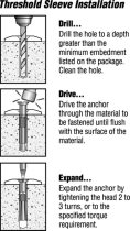
3.13INSTALLING THE ANCHOR: Anchor installation requires that holes be drilled into the concrete surface and the
included anchor bolts inserted and affixed: See Figure 3.
STEP 1. Using a ½ in. carbide drill bit, drill each hole a minimum of 3 ¾ in. deep. Clean out the holes
with a blow-out bulb or compressed air.
STEP 2. Assemble the washer and nut onto the bolt. Screw the nut onto the bolt until it is flush with the
top of the bolt to protect the threads. Place the bolt through anchor plate and into the hole. Drive the bolt
into the hole until the washer is pressed against the surface of the anchor plate.
STEP 3. Expand the anchor bolt by tightening the bolt to the installation torque of 55 ft. lbs. Minimum
embedment in concrete: 2¼ in.
Figure 2 - Anchor Locations

4
WARNING: Always wear safety glasses and other
necessary protective devices or apparel when installing
or working with anchor bolts.
CAUTION: Not recommended for use in lightweight
masonry such as block or brick.
CAUTION: Use of carbide drill bits manufactured within
ANSI B94.12-77 drill bit diameter requirements is
recommended for installation of this anchor bolt. Use of
core drills is not recommended to drill holes for use with
this anchor.
CAUTION: Not recommended for use in new concrete which has not had sufficient time to cure.
WARNING: User must read and follow the supplied instructions (or instructions supplied with non-supplied equipment) for
the associated equipment used in this kit (i.e. full body harness, shock absorbing lanyard with attached rope grab, and
rope lifeline). Failure to read and follow all instructions could result in serious or fatal injury.
IMPORTANT: For special (custom) versions of this product, follow the instructions herein (i.e. Compliance in a Can). If
enclosed, see attached supplement for additional instructions to be followed when using a customized product. If instructions
for any component of the system are missing or unusable, contact PROTECTA for a replacement set before use.
3.14MAKING CONNECTIONS: When using a hook to make a connection, be certain accidental disengagement (rollout)
cannot occur. Rollout occurs when interference between a hook and the mating connector causes the hook’s gate
or keeper to accidentally open and release. Self-locking snap hooks and self-closing and locking carabiners must
be used to reduce the possibility of rollout when making connections. Do not use hooks or connectors that will not
completely close over the attachment object. Never use non-locking snap hooks. Follow supplied instructions for
each system component.
3.15CONNECTING TO THE CONCRETE ANCHOR: Connection to the installed concrete anchor may be made using a
self locking snap hook or self closing carabiner ONLY. Do not use a knot to connect a lifeline to the concrete
anchor. Do not pass lanyard or lifeline through the anchor ring and hook back into lanyard or line. When
connecting, make sure connections are fully closed and locked. When using a shock absorbing lanyard (SAL),
ensure that the shock absorber end of the lanyard is connected closest to the dorsal D-ring of the harness (does
not apply to “Compliance in a Can” kit as the SAL is permanently attached to rope grab). If using a self retracting
lifeline, make sure device is properly positioned so that retraction is not hindered. Always protect lifeline/lanyard
from contact against sharp edges or abrasive surfaces. Make sure all connections are compatible in size, shape,
and strength. Never connect more than one personal fall arrest system to any single concrete anchor at a time.
WARNING: User must read and follow the supplied instructions (or instructions supplied with non-supplied equipment) for
the associated equipment used in this kit (i.e. full body harness, shock absorbing lanyard with attached rope grab, and
rope lifeline). Failure to read and follow all instructions could result in serious or fatal injury.
IMPORTANT: For special (custom) versions of this product, follow the instructions herein (i.e. Compliance in a Can). If
enclosed, see attached supplement for additional instructions to be followed when using a customized product. If
instructions for any component of the system are missing or unusable, contact PROTECTA for a replacement set before use.
1. Drill and clean
hole.
2. Drive assembled
bolt into hole.
3. Tighten to
appropriate torque.
Figure 3 - Installing Anchor Bolts

5
4.0 TRAINING
4.1 It is the responsibility of the user and purchaser of this equipment to ensure that they are familiar with these
instructions, trained in the correct care and use of, and are aware of the operating characteristics, application limits,
and the consequences of improper use of this equipment.
IMPORTANT: Training must be conducted without exposing the trainee to a fall hazard. Training should be repeated on a
periodic basis.
5.0 INSPECTION
IMPORTANT: If this equipment has been subjected to forces resulting from the arrest of a fall, it must be immediately
removed from service and destroyed.
5.1 FREQUENCY: Before use, visually inspect the anchor per the following steps:
STEP 1:Inspect the D-ring, plate, and bolts for physical damage. Look carefully for any signs of cracks, dents, or
deformities in the D-ring. Ensure that nuts are tightened to proper torque per manufacturer’s instructions.
STEP 2:Inspect the D-ring, plate, and bolts for signs of corrosion.
STEP 3:Ensure that the condition of the structure will support the anchor loads (see “Anchorage Strength
Requirements”). An anchor connected to questionable material or surfaces should not be used.
STEP 4:Ensure that the anchor is securely attached at all times.
STEP 5:Inspect each system component or subsystem per written instructions from manufacturer (inspection
procedures for other elements of the “Compliance in a Can” kit are included in this manual).
STEP 6:Record the inspection date and results in the inspection log included in the back of this manual.
NOTE: If inspection reveals a defective condition, remove the unit from service immediately and destroy, or contact
PROTECTA for more information. Only PROTECTA is authorized to make repairs to this equipment.
6.0 CLEANING, MAINTENANCE, AND STORAGE
6.1 No scheduled maintenance is required. If you have any questions concerning the condition of your AJ720A
Concrete Anchor, or have any doubts about putting it into service, contact PROTECTA. Additional maintenance and
servicing procedures (i.e. replacement parts) must be completed by PROTECTA. Unused components must be
stored in a clean dry location.
7.0 SPECIFICATIONS
7.1 ANCHOR PLATE AND D-RING
MATERIAL: Zinc plated stamped steel D-ring. Painted steel plate.
MINIMUM BREAKING STRENGTH: 5,400 lbs. minimum
WEIGHT: 3 lbs. (including anchor bolts)
SIZE: 6 in. X 6 in. X 1/4 in. steel plate, 9/16 in. diameter holes, 4 in. X 1/2 in. diameter anchor bolts.
CAPACITY: 310 lbs. total (one person, clothing, equipment).
7.2 ANCHOR BOLTS
LENGTH: 3.75 IN.
DIAMETER: .50 IN
SPECIFICATIONS: Meets GSA Specification FF-S-325, Group II, Type 4, Class 1.
ASTM E488.

6
Anchor Plate Anchor Bolt
7.3 DIMENSIONS:

7
ETADNOITCEPSNISMETINOITCEPSNI
DETON
NOITCAEVITCERROCECNANETNIAM
DEMROFREP
:yBdevorppA
:yBdevorppA
:yBdevorppA
:yBdevorppA
:yBdevorppA
:yBdevorppA
:yBdevorppA
:yBdevorppA
:yBdevorppA
:yBdevorppA
:yBdevorppA
:yBdevorppA
8.0 INSPECTION AND MAINTENANCE LOG
DATE OF MANUFACTURE: _______________________________________________________________________
MODEL NUMBER: ______________________________________________________________________________
DATE PURCHASED: ________________________________________________________________________________

8
USA Canada
3965 Pepin Avenue 260 Export Boulevard
Red Wing, MN 55066-1837 Mississauga, Ontario L5S 1Y9
Toll Free: 800-328-6146 Toll Free: 800-387-7484
Phone: (651) 388-8282 Phone: (905) 795-9333
Fax: (651) 388-5065 Fax: (905) 795-8777
www.protecta.com www.protecta.com
Form: 5902241
Rev: A
I S O
9 0 0 1
Certificate No. FM 39709
/