Page is loading ...

1
Contents
1.0 HOW TO USE THIS MANUAL 1
2.0 TRAINING 2
3.0 COMPONENT AND CONNECTOR COMPATIBILITY 2
4.0 FULL BODY HARNESS 4
5.0 VERTICAL LIFELINE AND ROPE GRAB SYSTEMS 5
6.0 SELF RETRACTING LIFELINE SYSTEMS 14
7.0 HORIZONTAL LIFELINE SYSTEMS 15
8.0 INSPECTION 18
9.0 CLEANING AND MAINTENANCE 22
10.0 SPECIFICATIONS 23
INSPECTION LOG 25
WARNING: These products are part of a personal
protective, rescue, or work support system. The user
must read and follow the manufacturer’s instructions
for each component of the system. These instructions
must be provided to the user of this equipment. The
user must read and understand these instructions,
or have them explained to them, before using this
equipment. Manufacturer’s instructions must be
followed for proper use and maintenance of this
equipment. If any questions regarding the use of this
equipment arise before or during the course of your
work, contact PROTECTA
1.0 HOW TO USE THIS MANUAL
1.1 Compliance In A Can systems are packaged to include either a vertical lifeline and rope grab system, a
self retracting lifeline (SRL) system, or a horizontal lifeline (HLL) system. Refer to the appropriate section of
this manual for the system requirements and limitations before installing your system.
Section 4 contains instructions for Full Body Harness use. The Vertical Lifeline and Rope Grab systems
instructions are located in section 5. Also refer to section 5 for instructions on installation of all the
anchorage connectors. SRL system instructions are in section 6 and HLL system instructions are in section 7.
Section 8 contains instructions on how to inspect the individual elements of your system before each use
and during periodic formal inspections by a competent person. A Log for recording the results of formal
inspections is included in the back of this manual.
For specifi cations of the individual pieces of equipment, see Section 10.
1.2 This manual contains information vital to your safety, and should be kept in a safe place for use as a
reference if needed. These products are part of a personal protective, rescue, or work support system.
The user must read and follow the manufacturer’s instructions for each component of the system. These
instructions must be provided to the user of this equipment. The user must read and understand these
instructions, or have them explained to them, before using this equipment. These instructions must be
followed for proper use and maintenance of this equipment.
© Copyright 2010 PROTECTA
Compliance In A Can
This manual is intended to meet the
Manufacturer’s Instructions as required by
ANSI Z359.1 and should be used as part of an
employee training program as required by OSHA.
Form: 5902234 Rev: C

2
2.0 TRAINING
2.1 TRAINING: It is the responsibility of the user to assure they are familiar with these instructions, and
are trained in the correct care and use of this equipment. The user must also be aware of the operating
characteristics, application limits, and the consequences of improper use of this equipment.
WARNING: Training must be conducted without exposing the trainee to a fall hazard and should be repeated on
a periodic basis.

3
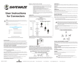
MAKING CONNECTIONS: Only use self-locking snap hooks and carabiners with this equipment. Only use
connectors that are suitable to each application. Ensure all connections are compatible in size, shape and
strength. Do not use equipment that is not compatible. Ensure all connectors are fully closed and locked.
PROTECTA connectors (snap hooks and carabiners) are designed to be used only as specifi ed in each
product’s user’s instructions. See Figure 2 for inappropriate connections. PROTECTA snap hooks and
carabiners should not be connected:
A. To a D-ring to which another connector is attached.
B. In a manner that would result in a load on the gate.
NOTE: Large throat opening snap hooks should not be connected to standard size D-rings or similar objects
which will result in a load on the gate if the hook or D-ring twists or rotates. Large throat snap hooks are
designed for use on fi xed structural elements such as rebar or cross members that are not shaped in a way that
can capture the gate of the hook.
C. In a false engagement, where features that protrude from the snap hook or carabiner catch on the
anchor and without visual confi rmation seems to be fully engaged to the anchor point.
D. To each other.
E. Directly to webbing or rope lanyard or tie-back (unless the manufacturer’s instructions for both the
lanyard and connector specifi cally allow such a connection).
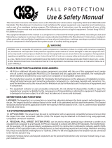
If the connecting element that a snap hook (shown) or carabiner attaches to is undersized or irregular in
shape, a situation could occur where the connecting element applies a force to the gate of the snap hook
or carabiner. This force may cause the gate (of either a self-locking or a non-locking snap hook) to open,
allowing the snap hook or carabiner to disengage from the connecting point.
1. Force is applied to the snap
hook.
2. The gate presses against
the connecting ring.
3. The gate opens allowing
the snap hook to slip off.
Figure 1 - Unintentional Disengagement (Roll-out)
Small ring or other
non-compatibly
shaped element
3.0 Component and Connector Compatibility
3.1 COMPATIBILITY OF COMPONENTS: PROTECTA equipment is designed for use with PROTECTA approved
components and subsystems only. Substitutions or replacements made with non-approved components
or subsystems may jeopardize compatibility of equipment and may affect the safety and reliability of the
complete system.
3.2 COMPATIBILITY OF CONNECTORS: Connectors are considered to be compatible with connecting
elements when they have been designed to work together in such a way that their sizes and shapes do
not cause their gate mechanisms to inadvertently open regardless of how they become oriented. Contact
PROTECTA if you have any questions about compatibility.
Connectors (hooks, carabiners, and D-rings) must be capable of supporting at least 5,000 lbs. (22.2kN).
Connectors must be compatible with the anchorage or other system components. Do not use equipment
that is not compatible. Non-compatible connectors may unintentionally disengage. See Figure 1. Connectors
must be compatible in size, shape, and strength. Self locking snap hooks and carabiners are required by
ANSI Z359.1 and OSHA, and in Canada, by CSA Z259.12.

4
F. To any object which is shaped or
dimensioned such that the snap
hook or carabiner will not close
and lock, or that roll-out could
occur.
4.0 FULL BODY HARNESS:
HARNESS PURPOSE: PROTECTA full
body harnesses are to be used as
components in personal fall arrest,
restraint, work positioning, or rescue
systems.
4.1 REQUIREMENTS
A. FULL BODY HARNESSES are
designed to act in concert with
other elements of a Personal Fall
Arrest System (PFAS) and arrest a fall from height while minimizing impact load on the wearer. Users
should not combine components or subsystems of the PFAS from manufacturers other than PROTECTA
unless it is determined by a qualifi ed person that they are compatible with one another. Incompatible
components may interfere with the safe operation or function of the equipment.
B. ENVIRONMENTAL HAZARDS: Use of this equipment with environmental hazards may require
additional precautions to prevent injury to the user or damage to the equipment. Hazards may include,
but are not limited to: heat, chemicals, corrosive environments, high voltage power lines, gases, moving
machinery, moving vehicles and sharp edges. Contact PROTECTA if you have questions about using this
equipment where environmental hazards may exist.
4.2 FULL BODY HARNESS LIMITATIONS
Full body harnesses are designed to act in concert with other elements of a Personal Fall Arrest System and
arrest a fall from height while minimizing impact load on the wearer. Users should not combine components
or subsystems of the PFAS from manufacturers other than PROTECTA unless it is determined by a qualifi ed
person that they are compatible with one another. Incompatible that they are compatible with one another.
Incompatible components may interfere with the safe operation or function of the equipment.
A. HEAT: This equipment is not designed for use in high temperature environments. Provide protection
for this equipment when using near welding, metal cutting, or similar activities. Hot sparks may burn
or damage this equipment. Contact PROTECTA for details on use of this equipment in high temperature
environments.
4.3 DONNING THE HARNESS
Step 1. Grasp the harness by the dorsal D-Ring and shake until straps hang down from harness body. Make
sure that the buckles are all unfastened. See Figure 3.
Step 2. Slip on the shoulder straps one at a time as if you were putting on a jacket. Be careful not to twist
the straps.
Step 3. Individually adjust each shoulder strap by pulling or releasing the slack end so that the sub-pelvic
strap is fi rmly in place under the buttocks.
Step 4. Pull each thigh strap through the crotch and fasten the parachute buckles by passing the male
buckle through the female. Be careful not to cross or twist the straps. Adjust the tension of the thigh
straps by pulling or releasing the slack end of the strap. Move the plastic keeper away from the
buckle edge to ease adjustment.
Step 5. Attach the chest strap parachute buckle and adjust the length so that the shoulder straps are
centered on each shoulder.
Step 6. Position the plastic strap keepers so that one is next to the parachute buckle and the other is at the
far end of the excess strap. Be certain that the harness is adjusted so that:
1) The dorsal D-ring is located as closely as possible to the center of the wearer’s back.
2) The sub-pelvic strap is located fi rmly in place under the wearer’s buttocks.
Figure 2 - Inappropriate Connections

5
3) The harness fi ts snugly. Proper fi t will allow the
wearer to perform normal work operations without
discomfort.
WARNING: All parachute buckles must be fastened and adjusted
properly before any work is performed. Failure to properly fasten and
adjust the harness can result in serious or death in the event of a fall
from height. If any uncertainty exists regarding the proper fi t of a
harness consult a qualifi ed person, or contact Protecta.
If it is determined that a larger size is necessary, consult
your local Protecta distributor, or contact Protecta directly for
information about a distributor in your area.
5.0 VERTICAL LIFELINE SYSTEMS
5.1 VERTICAL LIFELINE APPLICATIONS: Vertical lifeline systems
are intended to be used for fall arrest or restraint. These
systems are not designed for use as horizontal lifeline systems.
Applications include: Inspection work, construction, demolition,
maintenance, oil production, confi ned space rescue, window
washing.
5.2 VERTICAL LIFELINE REQUIREMENTS:
The anchorage strength required is dependent upon the
application:
A. FALL ARREST: Anchorages used for personal fall arrest
systems must be capable of sustaining static loads in the
directions permitted by the personal fall arrest system of
at least: 3,600 lbs. with certifi cation of a qualifi ed person;
or 5,000 lbs. without certifi cation. See ANSI Z359.1 for
certifi cation defi nition. When more than one personal fall
arrest system is attached to an anchorage, the strengths
stated above must be met at each anchorage location
independently.
From OSHA 1926.500 and 1910.66: Anchorages used
for attachment of personal fall arrest systems shall be
independent of any anchorage being used to support or
suspend platforms, and capable of supporting at least 5,000
lbs. per user attached, or be designed, installed, and used as
part of a complete PFAS which maintains a safety factor of at
least two, and is under the supervision of a qualifi ed person.
B. RESTRAINT: The restraint system must be attached to an
anchorage capable of sustaining static loads in the directions
permitted by the restraint system of at least 3,000 lbs. When
more than restraint system is attached to an anchorage,
the strengths stated above must be met at each anchorage
location independently.
5.3 LIMITATIONS:
A. CAPACITY: This equipment is designed for use by persons with a combined weight (person, clothing,
tools, etc.) of no more than 310 lbs. Only one personal protective system may be connected to an
anchor at any time.
B. FREE FALL: Personal Fall Arrest Systems (PFAS) must be rigged in such a way as to limit the free fall to
a maximum of 6 feet (reference ANSI Z359.1).
C. FALL CLEARANCE: Make certain that enough clearance exists in your fall path to prevent striking an
object. The amount of clearance needed is dependent upon the type of connecting subsystem used and
the anchorage location. See section 10 for lifeline elongation factor when determining fall clearance.
D. CORROSION: Use near sea water or other corrosive environments may require more frequent
inspections or servicing (replacement) to assure corrosion damage is not affecting the performance of
the product.
Step 1
Step 2
Step 3
Step 4
Figure 3 - Donning a Harness
Step 4 detail
Step 5

6
E. CHEMICAL HAZARDS: Solutions containing acids, alkali, or other caustic chemicals, especially at
elevated temperatures, may cause damage to this equipment. Consult PROTECTA if doubt exists
concerning installing this equipment where chemical hazards are present.
F. ENVIRONMENTAL HAZARDS: Use of this equipment in areas where environmental hazards exist may
require additional precautions to reduce the possibility of injury to the user or damage to the equipment.
Hazards may include, but are not limited to: high heat, caustic chemicals, corrosive environments, high
voltage power lines, explosive or toxic gases, moving machinery, or sharp edges.
G. SWING FALLS: See Figure 4. Swing falls occur when the
anchorage point is not directly above the point where a fall occurs.
The force of striking an object in a swing fall may cause serious
injury. Minimize swing falls by working as directly below the
anchorage point as possible. Do not permit a swing fall if injury
could occur.
H. FREE FALL: Never work above your anchorage point. Position
the rope grab as far up the lifeline as possible to limit your free
fall. Personal fall arrest systems must be rigged to limit free fall
distance to 6 feet.
I. FALL CLEARANCE: There must be suffi cient clearance in your fall
path to prevent striking an object or the lower level in the event of
a fall. The amount of clearance required is dependent upon the
application.
5.4 CONNECTING TO A VERTICAL LIFELINE: Use the self locking
snap hook that is attached to the vertical lifeline to connect to
the D-ring of the roof anchor. Ensure that the snap hook is fully
engaged and that the gate closes completely and locks. Do not tie
a knot in the lifeline. See Figure 5. The connection must support
5,000 lbs.
5.5 LIFELINE COUNTER WEIGHTS: Tension the lifeline to assure
smooth motion of the rope grab on the lifeline. To tension the
lifeline; suspend as much as possible of the full length of the lifeline
below the rope grab (12 feet minimum required); or secure the end
of the lifeline at working or ground level; or use a six to ten pound
counterweight. The method of tensioning used should be determined
by the job site conditions.
5.6 1/2 IN. ROPE GRAB
A. ATTACHING THE 1/2 in. ROPE GRAB TO THE LIFELINE:
See Figure 6.
Step 1. Ensure the rope grab is correctly positioned relative to the lifeline. The “up” arrow on the sleeve
must be pointing to the anchorage.
Step 2. Pivot the handle to its full upright position. This will draw back the rope
shoe to allow insertion of the lifeline into the housing.
Step 3. Hold the rope grab upright and feed the lifeline through the rope grab
from the top down.
Step 4. Check the locking action by lifting up the handle and releasing. The rope
grab must lock onto the lifeline. If the rope grab does not securely lock
onto the lifeline, repeat steps 1 through 3. Do not use if the rope grab will
not operate correctly.
WARNING: Lifelines used with this rope grab must meet the size, construction,
material properties, and specifi cations stated above.
B. USING AND POSITIONING THE 1/2 IN. ROPE GRAB ON THE LIFELINE:
See Figure 7.
UP
Figure 6 - Installation
Figure 5 - Making Connections
Figure 7 - Positioning
UP
to anchor
Figure 4 - Swing Fall

7
BEFORE EACH USE
Inspect all personal fall arrest equipment as specifi ed in section 8.
This rope grab is designed to remain in place on the lifeline. To reposition the rope grab on the lifeline, follow
these steps:
Step 1. To ascend, climb up normally. The rope grab will follow the climber. When working, position the rope
grab at or above your back D-ring to minimize free fall distance.
Step 2. To descend, climb down smoothly in a normal position. Allow the rope grab to “lead” the climber
down. If the rope grab locks, move upward slightly to release the rope grab and continue to
descend.
Step 3. To check the locking action of the rope grab, lift up the handle and release. The rope grab must lock
onto the rope. If the rope grab does not operate correctly, repeat attachment steps listed in section
5.6.
WARNING: Rope grab attachment and positioning procedures must be followed. Improper attachment may
cause the rope grab to slip or unlock from the lifeline, which may result in serious injury or death.
WARNING: Ensure the design of your work site and your working location
will allow the rope grab to remain locked on the lifeline when a fall occurs.
When a fall occurs, the lanyard must pull the handle on the rope grab down
to lock the rope grab onto the lifeline.
WARNING: The rope grab handle must not be prevented from locking onto
the lifeline by interference from objects, or be held open by hand when in
use. Failure to heed this warning may result in serious injury or death.
5.7 5/8 IN. ROPE GRAB
A. ATTACHING THE 5/8 in. ROPE GRAB TO THE LIFELINE:
Step 1. Position the rope grab so that the connecting ring is pointed
downward as in Figure 8. The “up” arrow stamped on the rope
grab body must be pointing to the anchorage.
Step 2. Pivot the connecting ring and locking lever upward to its full
upright position. This will draw back the brake shoe to allow
insertion of the lifeline into the housing.
Step 3. Hold the rope grab upright and feed the lifeline through the rope
grab from the top down.
Step 4. Release the locking lever and check the locking action by puling
the rope upward. The rope grab must lock onto the lifeline. If the
rope grab does not securely lock onto the lifeline, repeat steps 1
through 3. Do not use if the rope grab will not operate correctly.
WARNING: Lifelines used with this rope grab must meet the size,
construction, material properties, and specifi cations stated above.
B. USING AND POSITIONING THE 5/8 IN. ROPE GRAB ON THE
LIFELINE:
BEFORE EACH USE
Inspect all personal fall arrest equipment as specifi ed in section 8.
This rope grab is designed to remain in place on the lifeline. To reposition
the rope grab on the lifeline, follow these steps:
Step 1. To ascend, hold the rope below the rope grab and pull the rope
grab up the rope. The teeth in the brake shoe are angled to allow
the rope grab to be pulled up the rope. When working, position
the rope grab at or above your back D-ring to minimize free fall
distance.
Step 2. To descend, pull up on the connecting ring to open the locking
lever and release the rope from the brake shoe. Pull the rope
LOCKING LEVER
CONNECTING
RING
Figure 8 - 5/8 in. Rope Grab
LOCKING
LEVER IN OPEN
POSITION
INSTALLING
THE ROPE GRAB
ONTO A ROPE
PROPERLY
INSTALLED ROPE
GRAB
UP
to anchor

8
upward through the rope grab while the locking lever is in the up position. When your new location
is reached, release the locking lever and the rope grab will lock onto the rope.
Step 3. Check the locking action of the rope grab. The rope grab must lock onto the rope. If the rope grab
does not operate correctly, repeat attachment steps listed in section 5.6.
WARNING: Rope grab attachment and positioning procedures must be followed. Improper attachment may
cause the rope grab to slip or unlock from the lifeline, which may result in serious injury or death.
WARNING: The rope grab handle must not be prevented from locking onto the lifeline by interference from
objects, or be held open by hand when in use. Failure to heed this warning may result in serious injury or death.
5.8 LANYARD: Only the energy absorber supplied permanently attached to the rope grab may be used. This
energy absorber limits fall arrest forces to 900 lbs. and length is limited to 1.4 feet. If the energy absorber
is damaged, it must be replaced using an identical model.
5.9 BODY SUPPORT: For fall arrest applications, a full body harness must be
used. The integrated energy absorber must be attached to the dorsal D-ring
on the harness.
5.10 ROOF ANCHOR INSTALLATION
PURPOSE: PROTECTA’s roof anchor is designed to be used as a temporarily
installed (not for permanent installation) anchorage connector on wood frame
structures. See Figure 9. This anchorage connector may be used as part of
a personal fall arrest or restraint system. Do not attach a lifeline between
two or more roof anchors (i.e. horizontal lifeline system). Do not hang, lift
or support tools or equipment from this roof anchor or attach guylines for
antennas, phone lines, etc.
1. SITE PLAN : Before starting the roof
construction, a plan should be established as
to where the roof anchors will be installed and
when during the construction process they
may be used. The following are guidelines on
locating roof anchors :
• The roof anchor should be located at the roof
peak (when possible) and at least 6 feet from
any exposed edge. On very small roof areas,
locate the anchor as far from the roof edge as
possible.
• Do not install roof anchors on unsupported
roof structures such as eaves or gable
overhangs.
• Do not install roof anchors on facia boards.
• Roof anchors should be installed at 8 foot
spacing along the roof peak.
• Hip roofs require a roof anchor on each hip
face.
• On long low pitched roofs, multiple roof anchors should be installed along gable ends (6 feet from edge) to
reduce swing fall hazards.
Figure 10 shows typical roof anchor locations for various roof confi gurations.
2. ANCHORAGE STRENGTH: The anchorage strength required is dependent on the application. Following
are anchorage strength requirements for specifi c applications:
A. FALL ARREST: The structure to which the anchorage connector is attached must sustain static loads
applied in the directions permitted by the fall arrest system of at least: 3,600 lbs. with certifi cation of a
qualifi ed person, or 5,000 lbs. without certifi cation. See ANSI Z359.1 for certifi cation defi nition. When
more than one personal fall arrest system is attached to an anchorage, the strengths stated above must
be multiplied by the number of personal fall arrest systems attached to the anchorage. When more
than one anchor is installed to a structure, the strengths given in (A) or (B) above must be met at each
roof anchors installation point independently. EXAMPLE: If two roof anchors are installed onto a roof
structure, each anchor location must be independently capable of supporting 5,000 lbs. (or 3,600 lbs.
with certifi cation).
Figure 10 - Roof Anchor Locations
Figure 9 - Roof Anchor

9
From OSHA 1926.500 and 1910.66: Anchorages used for attachment of a personal fall arrest system
shall be independent of any anchorage being used to support or suspend platforms, and must support at
least 5,000 lbs. per user attached; or be designed, installed, and used as part of a complete personal fall
arrest system which maintains a safety factor of at least two, and is supervised by a qualifi ed person.
B. RESTRAINT: The structure to which the anchorage connector is attached must sustain static loads
applied in the directions permitted by the restraint system of at least 3,000 lbs. When more than one
restraint system is attached to an anchorage, the strengths stated above must be multiplied by the
number of restraint systems attached to the anchorage.
C. WORK POSITIONING: The structure to which the anchorage connector is attached must sustain
static loads applied in the directions permitted by the work positioning system of at least 3,000 lbs.,
or twice the potential impact load, whichever is greater. When more than one work positioning system
is attached to an anchorage, the strengths stated above must be multiplied by the number of work
positioning systems attached to the anchorage.
D. PERSONNEL RIDING: The structure to which the anchorage connector is attached must sustain static
loads applied in the directions permitted by the personnel riding system of at least 2,500 lbs. When
more than one personnel riding system is attached to an anchorage, the strengths stated above must be
multiplied by the number of personnel riding systems attached to the anchorage.
E. RESCUE: The structure to which the anchorage connector is attached must sustain static loads applied
in the directions permitted by the rescue system of at least 2,500 lbs. When more than one rescue
system is attached to an anchorage, the strengths stated above must be multiplied by the number of
rescue systems attached to the anchorage.
3. LIMITATIONS: The following limitations apply to the use of Roof Anchors
A. CAPACITY: This equipment is designed for use by persons with a combined weight (person, clothing,
tools, etc.) of no more than 310 lbs. Only one personal protective system may be connected to an
anchor at any time.
B. FREE FALL: Personal Fall Arrest Systems (PFAS) must be rigged in such a way as to limit the free fall
to a maximum of 6 feet (reference ANSI Z359.1). See associated connecting subsystem manufacturer’s
instructions for further information.
C. FALL CLEARANCE: Make certain that enough clearance exists in your fall path to prevent striking an
object. The amount of clearance needed is dependent upon the type of connecting subsystem used
(energy absorbing lanyard, self retracting lifeline, etc.), and the anchorage location.
D. CHEMICAL HAZARDS: Solutions containing acids, alkali, or other caustic chemicals, especially at
elevated temperatures, may cause damage to this equipment. Consult PROTECTA if doubt exists
concerning installing this equipment where chemical hazards are present.
E. ELECTRICAL HAZARDS: Do not install anchors where they or the user may come into contact with
electrical power lines.
F. ENVIRONMENTAL HAZARDS: Use of this equipment in areas where environmental hazards exist may
require additional precautions to reduce the possibility of injury to the user or damage to the equipment.
Hazards may include, but are not limited to: high heat, caustic chemicals, corrosive environments, high
voltage power lines, explosive or toxic gases, moving machinery, or sharp edges.
G. SWING FALLS: Swing falls occur when the anchorage point is not directly overhead. The force of
striking an object in a swing fall may cause serious injury or death. Minimize swing falls by working
as directly below the anchorage point as possible. Do not permit a swing fall if injury could occur.
Swing falls will signifi cantly increase the clearance required when a self retracting lifeline or other
variable length connecting subsystem is used. If a swing fall situation exists in your application, contact
PROTECTA before proceeding.
5.11 ROOF FRAMING: Roof framing members to which the roof anchors are attached must be in good condition.
Members must be free of splits, cracks, large knots, or other defects that may weaken the member. Do not
attach the roof anchor to rotted or deteriorated wood.
5.12 ATTACHING THE ROOF ANCHOR: Spread the anchor base legs apart to match the surface it will be
mounted on, either a roof peak or a fl at surface. Position the anchor on the roof such that the 12 nailing
holes along the center of the legs are over a roof (framing) member (see Figure 11). Push down to minimize
any gap between the anchor and sheathing, then drive nails through the preformed holes in the anchor legs.

10
Install all 20 nails. Use only 16d nails to install the
anchor (6 per leg into the rafters and sheathing, 4
per leg into the sheathing). Install all 20 nails.
WARNING: The AJ730A roof anchor must be positioned
on top of previously secured roof sheathing (do not
attach directly to rafter or truss member). All 20 nails
must be installed. If the roof anchor is not installed
properly, it will not hold the rated loads and serious injury
or death could occur.
WARNING: Use only 16d nails which have a complete
head. Do not use nails from nail guns. Never attach the
roof anchor with the legs still together (legs must be
spread apart).
5.13 CONCRETE ANCHOR INSTALLATION
1. CONCRETE ANCHOR APPLICATIONS: The
AJ720A Concrete Anchor is designed to be used as
a permanently installed anchorage connector on concrete surfaces. It is designed to be used only as the
anchorage connector for a single personal fall arrest system. Concrete anchors may be used for temporary
horizontal lifelines that limit loading to less than 2500 lbs. Do not hang, lift, or support tools or equipment
from the attached anchor.
2. CONCRETE ANCHOR REQUIREMENTS AND LIMITATIONS:
The anchorage strength required is dependent on the application. Following are anchorage strength
requirements for specifi c applications:
A. FALL ARREST: The structure to which the anchorage connector is attached must sustain static loads
applied in the directions permitted by the fall arrest system of at least: 3,600 lbs. with certifi cation of a
qualifi ed person, or 5,000 lbs. without certifi cation. See ANSI Z359.1 for certifi cation defi nition. When
more than one personal fall arrest system is attached to an anchorage, the strengths stated above must
be multiplied by the number of personal fall arrest systems attached to the anchorage. When more
than one anchor is installed to a structure, the strengths given in (A) or (B) above must be met at each
roof anchors installation point independently. EXAMPLE: If two roof anchors are installed onto a roof
structure, each anchor location must be independently capable of supporting 5,000 lbs. (or 3,600 lbs.
with certifi cation).
From OSHA 1926.500 and 1910.66: Anchorages used for attachment of a personal fall arrest system
shall be independent of any anchorage being used to support or suspend platforms, and must support at
least 5,000 lbs. per user attached; or be designed, installed, and used as part of a complete personal fall
arrest system which maintains a safety factor of at least two, and is supervised by a qualifi ed person.
B. RESTRAINT: The structure to which the anchorage connector is attached must sustain static loads
applied in the directions permitted by the restraint system of at least 3,000 lbs. When more than one
restraint system is attached to an anchorage, the strengths stated above must be multiplied by the
number of restraint systems attached to the anchorage.
C. WORK POSITIONING: The structure to which the anchorage connector is attached must sustain
static loads applied in the directions permitted by the work positioning system of at least 3,000 lbs.,
or twice the potential impact load, whichever is greater. When more than one work positioning system
is attached to an anchorage, the strengths stated above must be multiplied by the number of work
positioning systems attached to the anchorage.
D. PERSONNEL RIDING: The structure to which the anchorage connector is attached must sustain static
loads applied in the directions permitted by the personnel riding system of at least 2,500 lbs. When
more than one personnel riding system is attached to an anchorage, the strengths stated above must be
multiplied by the number of personnel riding systems attached to the anchorage.
E. RESCUE: The structure to which the anchorage connector is attached must sustain static loads applied
in the directions permitted by the rescue system of at least 2,500 lbs. When more than one rescue
system is attached to an anchorage, the strengths stated above must be multiplied by the number of
rescue systems attached to the anchorage.
Figure 11 - Roof Anchor Installation

11
3. LIMITATIONS: The following limitations apply to the use of Concrete Anchors
A. CAPACITY: This equipment is designed for use by persons with a combined weight (person, clothing,
tools, etc.) of no more than 310 lbs. Only one personal protective system may be connected to an
anchor at any time.
B. FREE FALL: Personal Fall Arrest Systems (PFAS) must be rigged in such a way as to limit the free fall
to a maximum of 6 feet (reference ANSI Z359.1). See associated connecting subsystem manufacturer’s
instructions for further information.
C. FALL CLEARANCE: Make certain that enough clearance exists in your fall path to prevent striking
an object. The amount of clearance needed is dependent upon the type of connecting subsystem
used (energy absorbing lanyard, self retracting lifeline, etc.), and the anchorage location. Refer to
manufacturer’s instructions of the connecting subsystem or component for more information on fall
clearance.
D. CHEMICAL HAZARDS: Solutions containing acids, alkali, or other caustic chemicals, especially at
elevated temperatures, may cause damage to this equipment. Consult PROTECTA if doubt exists
concerning installing this equipment where chemical hazards are present.
E. ELECTRICAL HAZARDS: Do not install anchors where they or the user may come into contact with
electrical power lines.
F. ENVIRONMENTAL HAZARDS: Use of this equipment in areas where environmental hazards exist may
require additional precautions to reduce the possibility of injury to the user or damage to the equipment.
Hazards may include, but are not limited to: high heat, caustic chemicals, corrosive environments, high
voltage power lines, explosive or toxic gases, moving machinery, or sharp edges.
G. SWING FALLS: Swing falls occur when the anchorage point is not directly overhead. The force of
striking an object in a swing fall may cause serious injury or death. Minimize swing falls by working
as directly below the anchorage point as possible. Do not permit a swing fall if injury could occur.
Swing falls will signifi cantly increase the clearance required when a self retracting lifeline or other
variable length connecting subsystem is used. If a swing fall situation exists in your application, contact
PROTECTA before proceeding.
5.14 ATTACHING THE ANCHOR : Anchor installation requires that holes be drilled into the concrete surface and
the included anchor bolts inserted and affi xed. These instructions must be followed precisely in order for the
system to perform as designed. Failure to follow these instructions could cause serious or fatal injury. Only
after installation of the anchorage bolts and plate is complete (including drying time, any pull-testing, etc.)
should a personal fall arrest system be attached.
5.15 ANCHOR LOCATION: Anchor plates
(AJ720A) must be located at structurally
sound points. Holes for the anchor must be
at least 4 inches from any free edge. When
more than one AJ720A Concrete Anchor
is mounted on an anchorage, they must
be separated by at least 10 inches. See
Figure 12.
NOTE: It is recommended that the holes be
drilled and the bolts installed with the anchor
plate in place, using the plate as a guide to keep
the drill from wandering.
5.16 INSTALLING THE ANCHOR: Anchor
installation requires that holes be drilled into the concrete surface and the included anchor bolts inserted
and affi xed: See Figure 13.
STEP 1. Using a ½ in. carbide drill bit, drill each hole a minimum of 3 ¾ in. deep. Clean out the holes with a
blow-out bulb or compressed air.
STEP 2. Assemble the washer and nut onto the bolt. Screw the nut onto the bolt until it is fl ush with the top
of the bolt to protect the threads. Place the bolt through anchor plate and into the hole. Drive the
bolt into the hole until the washer is pressed against the surface of the anchor plate.
Figure 12 - Anchor Locations

12
STEP 3. Expand the anchor bolt by tightening
the bolt to the installation torque of 55
ft. lbs. The minimum embedment in
concrete is 2¼ in.
WARNING: Always wear safety glasses and other
necessary protective devices or apparel when
installing or working with anchor bolts.
CAUTION: Not recommended for use in lightweight
masonry such as block or brick.
CAUTION: Use of carbide drill bits manufactured
within ANSI B94.12-77 drill bit diameter
requirements is recommended for installation of this
anchor bolt. Use of core drills is not recommended to
drill holes for use with this anchor.
CAUTION: Not recommended for use in new concrete which has not had suffi cient time to cure.
5.17 WEB AND WIRE ROPE SLING INSTALLATION:
1. WIRE ROPE AND WEB SLING ANCHOR APPLICATIONS: The wire rope sling and web anchor strap is
designed to be used as an anchorage connector for a personal fall arrest, restraint, work positioning,
suspension, or rescue system. Wire rope slings and web anchor straps may be used as anchorage
connectors for a horizontal lifeline if the system is designed, installed and used under the supervision of a
qualifi ed person. Do not hang, lift, or support tools or equipment from this equipment.
A. STRUCTURE: The structure to which the anchorage connector is attached must be free of corrosion,
cracks, deformities, or other defects that may weaken the structure. Do not attach an anchorage
connector to a vertical structure unless a means of restraining the connector from sliding down the
structure is present. If the anchorage connector were to slide down the structure in a fall arrest
situation, serious injury to the user is possible.
2. ANCHORAGE REQUIREMENTS:
The anchorage strength required is dependent on the application. Following are anchorage strength
requirements for specifi c applications:
A. FALL ARREST: The structure to which the anchorage connector is attached must sustain static loads
applied in the directions permitted by the fall arrest system of at least: 3,600 lbs. with certifi cation of a
qualifi ed person, or 5,000 lbs. without certifi cation. See ANSI Z359.1 for certifi cation defi nition. When
more than one personal fall arrest system is attached to an anchorage, the strengths stated above must
be multiplied by the number of personal fall arrest systems attached to the anchorage. When more
than one anchor is installed to a structure, the strengths given in (A) or (B) above must be met at each
roof anchors installation point independently. EXAMPLE: If two roof anchors are installed onto a roof
structure, each anchor location must be independently capable of supporting 5,000 lbs. (or 3,600 lbs.
with certifi cation).
From OSHA 1926.500 and 1910.66: Anchorages used for attachment of a personal fall arrest system
shall be independent of any anchorage being used to support or suspend platforms, and must support at
least 5,000 lbs. per user attached; or be designed, installed, and used as part of a complete personal fall
arrest system which maintains a safety factor of at least two, and is supervised by a qualifi ed person.
B. RESTRAINT: The structure to which the anchorage connector is attached must sustain static loads
applied in the directions permitted by the restraint system of at least 3,000 lbs. When more than one
restraint system is attached to an anchorage, the strengths stated above must be multiplied by the
number of restraint systems attached to the anchorage.
C. WORK POSITIONING: The structure to which the anchorage connector is attached must sustain
static loads applied in the directions permitted by the work positioning system of at least 3,000 lbs.,
or twice the potential impact load, whichever is greater. When more than one work positioning system
is attached to an anchorage, the strengths stated above must be multiplied by the number of work
positioning systems attached to the anchorage.
1. Drill and clean
hole.
2. Drive
assembled bolt
into hole.
3. Tighten to
appropriate
torque.
Figure 13 - Installing Anchor Bolts

13
D. PERSONNEL RIDING: The structure to which the anchorage connector is attached must sustain static
loads applied in the directions permitted by the personnel riding system of at least 2,500 lbs. When
more than one personnel riding system is attached to an anchorage, the strengths stated above must be
multiplied by the number of personnel riding systems attached to the anchorage.
E. RESCUE: The structure to which the anchorage connector is attached must sustain static loads applied
in the directions permitted by the rescue system of at least 2,500 lbs. When more than one rescue
system is attached to an anchorage, the strengths stated above must be multiplied by the number of
rescue systems attached to the anchorage.
3. LIMITATIONS:
A. CAPACITY: This equipment is designed for use by persons with a combined weight (person, clothing,
tools, etc.) of no more than 310 lbs. Only one personal protective system may be connected to an
anchor at any time.
B. FREE FALL: Personal Fall Arrest Systems (PFAS) must be rigged in such a way as to limit the free fall
to a maximum of 6 feet (reference ANSI Z359.1). See associated connecting subsystem manufacturer’s
instructions for further information.
C. FALL CLEARANCE: Make certain that enough clearance exists in your fall path to prevent striking an
object. The amount of clearance needed is dependent upon the type of connecting subsystem used
(energy absorbing lanyard, self retracting lifeline, etc.), and the anchorage location.
D. CHEMICAL HAZARDS: Solutions containing acids, alkali, or other caustic chemicals, especially at
elevated temperatures, may cause damage to this equipment. Consult PROTECTA if doubt exists
concerning installing this equipment where chemical hazards are present.
E. ELECTRICAL HAZARDS: Do not install anchors where they or the user may come into contact with
electrical power lines.
F. ENVIRONMENTAL HAZARDS: Use of this equipment in areas where environmental hazards exist may
require additional precautions to reduce the possibility of injury to the user or damage to the equipment.
Hazards may include, but are not limited to: high heat, caustic chemicals, corrosive environments, high
voltage power lines, explosive or toxic gases, moving machinery, or sharp edges.
G. SWING FALLS: Swing falls occur when the anchorage point is not directly overhead. The force of
striking an object in a swing fall may cause serious injury or death. Minimize swing falls by working
as directly below the anchorage point as possible. Do not permit a swing fall if injury could occur.
Swing falls will signifi cantly increase the clearance required when a self retracting lifeline or other
variable length connecting subsystem is used. If a swing fall situation exists in your application, contact
PROTECTA before proceeding.
5.18 INSTALLING THE WEB STRAP CHOKER ANCHOR SLING: Place the web strap over the anchorage with
the labels facing out. Both ends of the web strap must be hanging below the anchorage as shown in Figure
14. With the web strap positioned on the anchorage, pass the D-ring through the web loop. Slide the web
loop up to the anchorage, over the webbing attached to the small D-ring. Pull the small D-ring down to take
up slack that was made by moving the large D-ring up. The web strap should be tightly wrapped around the
anchorage with the small D-ring hanging free. You may shorten the distance that the attachment ring hangs
from the anchorage by wrapping the webbing around the anchorage several times. Pass the D-ring through
the web loop on each pass.
5.19 INSTALLING THE WIRE ROPE SLING: Place the wire rope sling over the anchorage. The D-rings must
be hanging below the anchorage as shown in Figure 15. With the sling positioned on the anchorage, pass
the small attachment ring through the large ring. Slide the large ring up to the anchorage, over the wire
rope attached to the small attachment ring. Pull the small attachment ring down to take up slack that was
made by moving the large ring up. The wire rope sling should be tightly wrapped around the anchorage with
the small attachment ring hanging free. You may shorten the distance that the attachment ring hangs from
the anchorage by wrapping the adapter around the anchorage several times. Pass the small attachment
ring through the large ring on each pass. When the installation is complete, any connections to the tie-off
adapter must be made to the small attachment ring.

14
6.0 SELF RETRACTING LIFELINE SYSTEMS
6.1 SRL APPLICATION: PROTECTA self retracting lifeline (SRL)
systems are intended to be used in situations where worker
mobility and fall protection is needed (inspection work, general
construction, maintenance work, oil production, confi ned space
work, etc.) See Figure 16.
6.2 MAKING CONNECTIONS: Attach the self retracting lifeline
(SRL) to the D-ring of the anchorage connector using the
supplied carabiner. Make sure the carabiner closes completely
and locks.
A. OPERATION: Inspect the SRL as described in section 8.0.
Connect the SRL to a suitable anchorage or anchorage
connector as described above. Connect the self locking snap
hook or self locking/ self closing carabiner on the end of the lifeline to the fall arrest (dorsal D-ring).
Ensure connections are compatible in size, shape, and strength. Ensure the snap hook is securely closed
and locked.
BEFORE EACH USE inspect all personal fall arrest equipment as specifi ed in section 8.0.
B. USE: When attached to the SRL, the worker is free to move about within recommended working areas
at normal speeds. See Figure 16. The lifeline should extend smoothly and retract without hesitation.
While using, always ensure that there is constant tension on the lifeline. Slack in the wire rope could
result in an increase in fall distance. If slack line condition is created in normal use the unit should be
returned to PROTECTA for service. Should a fall occur, the SRL will lock and arrest the fall. Upon rescue,
remove the SRL from use. Inspect as described in section 8.0. When working with the SRL, allow the
lifeline to recoil back into the device under control. A short tag line may be required to extend or retract
the lifeline during connection and disconnection. Allowing the lifeline to be fully extended for long
periods of time may cause premature weakening of the retraction spring.
Figure 16- SRL Application
Figure 15 - Wire Rope Anchor Sling Installation
Figure 14 - Webstrap Anchor Sling installation

15
6.3 SRL LIMITATIONS
A. ELECTRICAL HAZARDS: For web and synthetic rope models, there is a possibility of moisture
absorption by the lifeline. Moisture absorbed by the lifeline may provide a path for electrical current to
fl ow, resulting in electrical shock. Use caution when the lifeline may contact high voltage power lines.
For wire rope models, there is a possibility of electric current fl owing through the lifeline. Use caution
where the lifeline may contact high voltage power lines.
B. CAPACITY: The SRL is for use by persons with a combined weight (person, clothing, tools, etc.) of 75
lbs. minimum and 310 lbs. maximum. No more than one person can connect to an SRL.
C. LOCKING SPEED: Situations which do not allow for an unobstructed fall path should be avoided.
Working in confi ned or cramped spaces may not allow suffi cient speed to cause the SRL to lock in a fall.
Working on slowly shifting materials, such as sand or grain, may not allow suffi cient speed to cause the
SRL to lock. A similar situation may occur on low pitched roofs, where a worker may slide instead of fall.
A clear path is required to ensure positive locking of the SRL.
D. FALL CLEARANCE: Make certain that enough clearance exists in your fall path to prevent striking an
object. The amount of clearance needed is dependent upon the type of connecting subsystem used
(energy absorbing lanyard, self retracting lifeline, etc.), and the anchorage location.
E. NORMAL OPERATION: Normal operation will allow the full length of the lifeline to extend and retract
with no hesitation when extending and no slack when retracting as the worker moves at normal speeds.
If a fall occurs, a speed sensing brake system will activate, stopping the fall and absorbing much of the
energy created. For falls that occur near the end of the lifeline travel, the reserve lifeline system will
ensure a reduced impact fall arrest. If a fall has been arrested, the SRL must be taken out of service
and inspected. Sudden or quick movements should be avoided during the normal work operation, as this
may cause the SRL to lock-up.
F. CHEMICAL HAZARDS: Solutions containing acids, alkali, or other caustic chemicals, especially at
elevated temperatures, may cause damage to this equipment. Consult PROTECTA if doubt exists
concerning installing this equipment where chemical hazards are present.
G. ENVIRONMENTAL HAZARDS: Use of this equipment in areas where environmental hazards exist may
require additional precautions to reduce the possibility of injury to the user or damage to the equipment.
Hazards may include, but are not limited to: high heat, caustic chemicals, corrosive environments, high
voltage power lines, explosive or toxic gases, moving machinery, or sharp edges.
7.0 HORIZONTAL LIFELINE SYSTEMS
7.1 APPLICATIONS: The PROTECTA Synthetic Rope Horizontal Lifeline System is designed for use as an
anchoring means for one or two persons. Use the PROTECTA Horizontal Lifeline System where horizontal
mobility and fall protection are required.
7.2 REQUIREMENTS:
A. PERSONAL FALL ARREST SYSTEM COMPONENTS: The PROTECTA horizontal lifeline must be
used with PROTECTA approved components and subsystems. Non-approved components may be
incompatible, and could affect the safety and reliability of the complete system. Personal fall arrest
components used with this system must meet all applicable OSHA and ANSI requirements. A full body
harness must be used with this system.
B. PERSONAL FALL ARREST SYSTEM CONNECTORS: Connectors used to attach to the attachment
O-ring on the horizontal lifeline (hooks, carabiners, D-rings) must support at least 5,000 lbs. Connectors
and attachment elements must be compatible in size, shape, and strength. Non-compatible connectors
may unintentionally disengage (roll-out). Do not use non-locking connectors with this system.
C. ANCHORAGE CONNECTORS: Connectors used to attach the horizontal lifeline to end anchors must be
compatible with the connection point. The connection must be positive; and, with connecting elements,
capable of sustaining a 5,000 lbs. load without failure.
D. STRUCTURE LOAD: Structural anchorage points must be rigid, and capable of supporting at least 3,600
lbs. along the axis of the horizontal lifeline. Anchorages must also support at least 3,600 lbs. applied in
all potential directions of fall arrest that are perpendicular to the axis of the horizontal lifeline.

16
WARNING: Anchorages must be rigid. Large deformations of the anchorage will affect system performance, and
may increase the required fall clearance below the system, which could result in serious injury or death.
7.3 LIMITATIONS: The following limits apply to the installation and use of the PROTECTA Horizontal Lifeline
System. Other limitations may apply:
IMPORTANT: OSHA regulations state that horizontal lifelines shall be installed and used under the supervision
of a qualifi ed person (see the following for defi nition) as part of a complete personal fall arrest system that
maintains a safety factor of at least two.
Qualifi ed Person: An individual with a recognized degree or professional certifi cate, and extensive knowledge
and experience in the subject fi eld, who is capable of design, analysis, evaluation, and specifi cation in the subject
work, project, or product. Refer to OSHA 1910.66, 1926.32, and 1926.502.
A. HORIZONTAL LIFELINE SPAN: The maximum span distance is 60 feet. The span length must be
reduced when clearance is limited. See Figure 17 for clearance information.
B. ANCHORAGES: The PROTECTA horizontal lifeline must be installed on anchorages that meet the
requirements specifi ed previously.
C. SYSTEM CAPACITY: The maximum capacity of the PROTECTA horizontal lifeline is one person. The
maximum weight of each person, including tools and clothing, is 310 lbs.
D. CONNECTING SUBSYSTEM: The user’s connecting subsystem must limit fall arrest forces to 900 lbs.
or less.
E. FREE FALL: Rig and use the personal fall arrest system such that the maximum potential free fall does
not exceed Government regulatory and subsystem manufacturer’s requirements.
F. SWING FALLS: Swing falls occur when the anchorage point is not directly overhead. The force of
striking an object in a swing fall may cause serious injury or death. Minimize swing falls by working
as directly below the anchorage point as possible. Do not permit a swing fall if injury could occur.
Swing falls will signifi cantly increase the clearance required when a self retracting lifeline or other
variable length connecting subsystem is used. If a swing fall situation exists in your application, contact
PROTECTA before proceeding.
G. BODY SUPPORT: A full body harness must be used with the PROTECTA Horizontal Lifeline System.
H. CONNECTING SUBSYSTEM: The connecting subsystem is the portion of the personal fall arrest
system that connects the horizontal lifeline subsystem and harness fall arrest attachment element. The
connecting subsystem must limit forces applied to the horizontal lifeline to 900 lbs. or less.
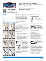
7.4 HORIZONTAL LIFELINE INSTALLATION: Figure 17 shows a typical horizontal lifeline (HLL) installation.
When using an energy absorbing lanyard to connect to the system, the end anchorages must be located at
a height which will limit the free fall to six (6) feet. When using a self retracting lifeline (SRL) to connect to
the system, the end anchorages must be located above the user. The SRL, when fully retracted, must be
above the harness attachment level.
The horizontal lifeline system should be
positioned at a level that will minimize
free fall while allowing ease of use. The
horizontal lifeline should be positioned
near the work location to minimize
swing fall hazards. The connecting
subsystem length should be kept as
short as possible to reduce the potential
free fall and required clearance distance.
See Figures 17 and 18 for minimum fall
clearances required. Both anchorages
must be installed at approximately the
same elevation, so that the horizontal
lifeline system is not sloped more than
fi ve (5) degrees.
Step 1. Install the anchor sling to the anchor structure at both ends of the planned HLL installation. See
section 5.18/5.19.
Figure 17 - Fall Clearance for Energy Absorbing
Lanyards
Working
surface
of HLL
Vertical clearance
from lower level
or obstruction to
working surface
Elevation of lower
level or obstruction
3 FT 4 FT 5 FT 6 FT
0-10 11'-2" 12'-2" 13'-2" 14'-2"
10-15 11'-10" 12'-10" 13'-10" 14'-10"
15-20 12'-5" 13'-5" 14'-5" 15'-5"
20-25 13' 14' 15' 16'
25-30 13'-7" 14'-7" 15'-7" 16'-7"
30-35 14'-2" 15'-2" 16'-2" 17'-2"
35-40 14'-10" 15'-10" 16'-10" 17'-10"
40-45 15'-5" 16'-5" 17'-5" 18'-5"
45-50 16' 17' 18' 19'
50-55 16'-7" 17'-7" 18'-7" 19'-7"
55-60 17'-2" 18'-2" 19'-2" 20'-2"
ENERGY ABSORBER LANYARD LENGTH
CLEARANCE CHART
SPAN (IN FEET)
Span Length
Instructions for use of
Clearance Chart:
Step 1. Locate the row on the left
of the table representing the length
of the span between stanchions for
the horizontal lifeline (HLL) being
analyzed.
Step 2. Locate the column on top
representing the length of the lanyard
with integral energy absorber being
used with the HLL system.
Step 3. The minimum allowable verti-
cal clearance needed from the lower
level or obstruction to the working
surface of the HLL is displayed at the
intersection of the row and column
determined in steps 1 and 2.

17
Working
surface
of HLL
Vertical clearance
from lower level
or obstruction to
working surface
Elevation of lower
level or obstruction
0 -10 10' - 9"
10 -20 11' - 11"
20 - 25 13' - 2"
30 - 40 14' - 6"
40 - 50 15' - 7"
50 - 60 16' - 8"
CLEARANCE CHART
Span Length
Span
(in feet)
Clearance
Step 2. Connect the carabiner on the
turnbuckle end of the HLL
assembly to one of the anchor
slings.
Step 3. Extend the turnbuckle so that
1/2 inch of threads remain
exposed in the turnbuckle body
slots.
Step 4 . Connect the carabiner on the
thimble clamp end of the HLL
assembly to the other wire rope
sling. Loosen the cable clips at
the end of the cable assembly
and pull the wire rope tight
to remove slack. Secure the
cable clip 1 1/2 inches from the
thimble clamp as shown in Figure 19. At least 8 inches of wire rope must extend out from the free
cable clip. Torque cable clips to 45 ft-lbs and thimble clamp nuts to 40 ft-lbs.
Step 5. To pre-load the system, tighten the wire rope by rotating the turnbuckle body. The unrestrained jaw
of the turnbuckle must be prevented from turning to prevent twisting of the wire rope. Tension the
wire rope until the sag on the system at mid-span is 6 inches or less, with no weight on the wire
rope. The turnbuckle will not over tension the wire rope.
Step 6. After pre-loading the system, re-torque all cable clips to values specifi ed previously.
7.5 USE OF THE HLL SYSTEM:
A. PERSONAL FALL ARREST SYSTEM COMPONENTS: Inspect and don the full body harness according
to section 7. Attach the energy absorbing pack end of the lanyard to the dorsal connection on the
harness.
B. CONNECTING TO THE HLL SYSTEM: Approach the work area using the appropriate access equipment.
Connect snaphook of the free end of the lanyard to an O-ring on the HLL. Make sure the snaphook
closes completely and locks.
C. WALKING ALONG THE SYSTEM: Once attached to the HLL System, the lanyard will follow the user
along the lifeline.
WARNING: Movement along the horizontal lifeline must be done manually by the user of the system. Never
allow moving stock (such as railcars) to move the user along the lifeline. This could cause serious injury or death.
D. HAZARDOUS SITUATIONS: Do not take unnecessary risks, such as jumping or reaching too far from
the edge of the working surface. Do not allow the connecting subsystem to pass under arms or between
feet. To avoid inadequate fall clearance, do not climb above the HLL. To avoid swing fall hazards, do not
work too far from either side of the HLL.
Figure 18 - Fall Clearance for Self Retracting Lifelines
WARNING: The
SecuraSpan HLL system
is approved for use
with SALA Talon, SALA
11-ft. Web UltraLok,
and Protecta Rebel SRLs
only. Clearance values
(see section 3.2) may
not be accurate if used
with other SRL models.
WARNING: Clearance chart only applies
to workers located directly adjacent to the
HLL with their SRL connected to the HLL
immediately next to them. Working away
from the point where the SRL connects to
the HLL will increase fall clearance.
Figure 19 - Horizontal Lifeline Installation

18
8.0 INSPECTION
8.1 BEFORE EACH USE
Inspect all personal fall arrest equipment as specifi ed in the following sections.
8.2 FORMAL INSPECTION
A formal inspection of the anchorage connector must be performed at least annually by a competent person
other than the user. The frequency of formal inspections should be based on conditions of use or exposure.
Record the inspection results in the inspection and maintenance log at the back of this manual.
IMPORTANT: If this equipment has been subjected to forces resulting from the arrest of a fall, it must be
immediately removed from service and destroyed or returned to PROTECTA for possible repair.
IMPORTANT: Extreme working conditions (harsh environments, prolonged use, etc.) may require increasing the
frequency of inspections.
IMPORTANT: Only PROTECTA or parties authorized in writing may make repairs to this equipment
8.3 ROPE GRAB AND ENERGY ABSORBER INSPECTION
A. ROPE GRAB:
Step 1: Inspect the handle and rope shoe for bends, cracks, and deformities. All fasteners must be securely
attached. Operation of the handle and rope shoe must be free and smooth. The spring must be
secure and of suffi cient strength to pull the handle down.
Step 2. Inspect the rope grab’s body for wear on the inside where the rope passes through it.
B. ENERGY ABSORBER:
Step 1. Inspect energy absorber component hardware (snap hook and carabiner). These items must not
be damaged, broken, distorted, or have any sharp edges, burrs, cracks, worn parts, or corrosion.
Ensure the connecting hooks work properly. Hook gates must move freely and lock upon closing.
Step 2. Inspect the energy absorber component per the following as applicable:
WEBBING AND STITCHING: Webbing material must be free of frayed, cut, or broken fi bers.
Check for tears, abrasions, mold, burns, or discoloration, etc. The webbing must be free of excessive
soiling, heavy paint buildup, and rust staining. Check for chemical or heat damage indicated by
brown, discolored, or brittle areas. Check for ultraviolet damage indicated by discoloration and the
presence of splinters or slivers on the webbing surface. All of the above factors are known to reduce
webbing strength. Inspect stitching for pulled or cut stitches. Broken stitches may be an indication
the energy absorber component has been impact loaded and must be removed from service.
Step 3. ENERGY ABSORBING COMPONENT: Inspect the energy absorber to determine if it has been
activated. Ensure the energy absorber cover is secure and not torn or damaged. When activated the
webbing will tear out of the energy absorber cover. There should be no evidence of elongation
Step 4. All labels should be present and fully legible. See section 11.0.
Step 5. If inspection reveals an unsafe or defective condition, remove the rope grab from service and
destroy, or contact an authorized service center for repair.
Step 6. Record the inspection date and results in the inspection log in the back of this manual.
IMPORTANT: Do not alter or attempt to repair the rope grab. Do not make substitutions for the rope grab parts.
Repairs may only be performed by an authorized service center.
8.4 VERTICAL LIFELINE INSPECTION
Step 1. Inspect lifeline hardware (snap hooks, ferrules, thimbles, etc.). These items must not be damaged,
broken or distorted. These items must be free of sharp edges, burrs, cracks, worn parts, or
corrosion. Hook gates must move freely and lock upon closing.
Step 2. Inspect rope for concentrated wear. Material must be free of frayed strands, broken yarns, cuts,
abrasions, burns, and discoloration. The rope must be free of knots, excessive soiling, paint build-
up, and rust staining. Rope splices must be tight, with fi ve full tucks, and thimbles must be held
fi rmly by the splice. Check for chemical or heat damage; indicated by brown, discolored, or brittle
areas. Check for ultraviolet damage; indicated by discoloration and splinters and slivers along the

19
rope surface. All of the above factors are known to reduce rope strength. Damaged or questionable
rope should be replaced.
Step 3. Inspect labels. All labels must be present and fully legible. See section 11.0.
Step 4. Inspect each system component or subsystem according to manufacturer’s instructions.
Step 5. If inspection reveals an unsafe or defective condition, remove the rope grab from service and
destroy, or contact an authorized service center for repair.
Step 6. Record the inspection date and results in the inspection log included in the back of this manual.
8.5 HINGED ROOD ANCHOR INSPECTION
Step 1. Inspect the Roof Anchor for physical damage. Look carefully for any signs of cracks, dents, or
deformities in the metal. Check for bending, the roof anchor legs should be fl at. Rivets should be
securely attached and fully clinched (not pulling through hole).
Step 2. Inspect the Roof Anchor for signs of excessive corrosion.
Step 3. Ensure the condition of the roof anchor will support the Roof Anchor loads. An anchor connected to
rotten or deteriorated wood should not be used.
Step 4: Ensure the Roof Anchor is still securely attached to the support structure. If it has become loose, do
not use it.
Step 5: If inspection reveals a defective condition, remove unit from service immediately and destroy, or
contact a factory authorized service center for repair.
Step 6: Record the inspection date and results in the inspection log included in the back of this manual.
8.6 CONCRETE ANCHOR INSPECTION
Step 1: Inspect the D-ring, plate, and bolts for physical damage. Look carefully for any signs of cracks,
dents, or deformities in the D-ring. Ensure that nuts are tightened to proper torque.
Step 2: Inspect the D-ring, plate, and bolts for signs of corrosion.
Step 3: Ensure that the condition of the structure will support the anchor loads (see “Anchorage Strength
Requirements”). An anchor connected to questionable material or surfaces should not be used.
Step 4: Ensure that the anchor is securely attached at all times.
Step 6: If inspection reveals a defective condition, remove unit from service immediately and destroy, or
contact a factory authorized service center for repair.
Step 7: Record the inspection date and results in the inspection log included in the back of this manual.
8.7 WIRE ROPE SLING AND WEB SLING INSPECTION
Step 1. Inspect the anchorage connector hardware, including, wire rope, D-rings, and O-rings. These items
must not be damaged, broken, distorted or have any sharp edges, burrs, cracks, worn parts, or
corrosion.
Step 2. Inspect the anchorage connector webbing and stitching. The webbing must be free of frayed, cut
or broken fi bers. Check for tears, abrasions, mold, or discoloration. The webbing must be free of
knots, excessive soiling, heavy paint build-up, and rust staining. Check for chemical or heat damage,
indicated by brown, discolored, or brittle areas. Check for ultraviolet degradation, indicated by
discoloration and the presence of splinters or slivers on the webbing surface. Check for pulled or
cut stitches. Broken stitches may be an indication that the anchorage connector has been impact
loaded and must be removed from service. All the above factors are known to reduce the strength
of the anchorage connector. Damaged or questionable anchorage connectors must be removed from
service.
Step 3. On wire rope models, inspect wire rope for cuts, kinks, broken wires, bird-caging, corrosion,
welding splatter, chemical contact areas, or severely abraded areas. Inspect ferrules for cracks or
damage and inspect wire rope for corrosion and broken wires. Damaged or questionable anchorage
connectors must be removed from service.
Step 4. Check that all labels are present and fully legible. See section 11.0

20
Step 5. If inspection reveals an unsafe or defective condition, remove the anchorage connector from service
and destroy it.
Step 6. Record the inspection date and results in the inspection log included in the back of this manual.
8.8 SELF RETRACTING LIFELINE WIRE ROPE AND HOUSING INSPECTION
CAUTION: Device should be stored with wire rope retracted during periods of non-use. If after inspection there
is any doubt as to the safety or appearance of the device, it should be removed from service and returned to
PROTECTA for further inspection.
A. HOUSING
Step 1. Inspect the connector at top of device and ensure freedom of movement. Check for signs of
distortion, cracks, burns, or worn parts and ensure that keeper is closed.
Step 2. Inspect The nut and bolt retaining connecting hook for signs of distortion, cracks, burns, and wear.
Step 3. Inspect. The main housing for signs of distortion or cracks, that the housing sections fi t together
with no gaps, and that all screws and rivets are present and tight.
Step 4. Inspect the device for spring action; the entire length of the wire rope should retract easily and fully
after extension.
Step 5. Inspect the locking action of the device: jerk on the end of the wire rope several times to ensure the
wire rope locks each time.
Step 6. Inspect the snap hook for signs of distortion, cracks, burns, and wear.
Step 7. Check that all labels are present and fully legible.
Step 8. Inspect the entire device for corrosion.
Step 9. Record the inspection date and results in the inspection log included in the back of this manual.
B. WIRE ROPE INSPECTION
CAUTION: Before beginning this procedure ensure that you are wearing gloves as broken wires along the wire
rope can cause severe cuts and lacerations.
Step 1. Begin the wire rope inspection procedure at the ferrule, check that it is correctly fi tted and there are
no signs of distortion, cracks, or corrosion.
Step 2. Check mechanical swages for signs of cracks, distortion, or corrosion-ensure that they are fi tted
correctly and are not cutting.
Step 3. Pass the wire rope slowly through your hands and fl ex it every few inches to inspect for broken
wires.
Step 4. Check the entire length of the wire rope for signs of deterioration or damage such as:
Mechanical damage/crushing: Crushing the wire rope often results in a fl attened or bent section
of the wire rope.
Mechanical damage/cutting: Movement over sharp edges or projections while the wire rope is
under tension can result in damaged strands and broken wires.
Abrasion: The outer wire strands appear fl attened and are brighter in appearance.
Strand Core Protrusion: Core protrusion usually results from the wire rope having been subject to
a shock load.
Kinking: Kinking occurs by the deformation of the wire rope during handling when a loop is formed
and then tightened without allowing for rotation about its axis. Typical examples of localized wear
and deformation are created at a previously kinked portion of the wire rope.
Corrosion: The presence of corrosion on the exterior surface of the wire rope is recognizable by its
roughness and pitting. Wire breaks will generate from these cracks or pitting.
Electric Arcing/Heat damage: Heat damage is noticeable by a blue coloring on the wire surface
or by fusion of the wire surface and the presence of welding signs.
Step 5. Snap Hooks: Check snap action, ensure that the return spring is functioning properly and that there
is not sideways play on the latch in the closed position. Check the hooks for distortion, sharp edges,
/