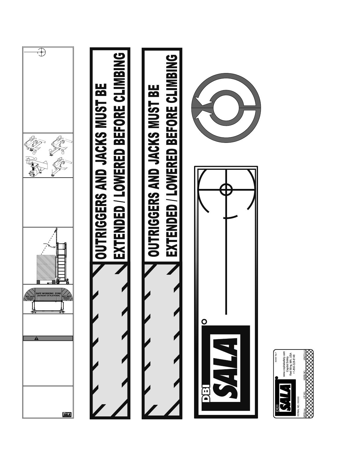
3M DBI-SALA® FlexiGuard™ Supported Ladder System 8530397, 1 EA Operating instructions

Type
Operating instructions

3M DBI-SALA® FlexiGuard™ Supported Ladder System 8530397, 1 EA is a mobile work platform with a rail fall arrest system for safe access and egress to elevated work areas. It can support up to two people with a combined weight of 310 lbs each. The system features a maximum arresting force of 900 lbs and a swing fall hazard warning to minimize the risk of injury. It also has adjustable outriggers for stability and foam bumpers for added protection. The ladder provides easy access to the work platform, and the safety gates prevent accidental falls.

3M DBI-SALA® FlexiGuard™ Supported Ladder System 8530397, 1 EA is a mobile work platform with a rail fall arrest system for safe access and egress to elevated work areas. It can support up to two people with a combined weight of 310 lbs each. The system features a maximum arresting force of 900 lbs and a swing fall hazard warning to minimize the risk of injury. It also has adjustable outriggers for stability and foam bumpers for added protection. The ladder provides easy access to the work platform, and the safety gates prevent accidental falls.

5903355 REV B © Copyright 2012 DB Industries, Inc.
User Instruction Manual
MOBILE ACCESS WORK PLATFORM WITH RAIL F.A.S
This manual is intended to be used as part of an employee training
program as required by OSHA.
Instructions for the following series products:
MOBILE ACCESS WORK PLATFORM
WITH RAIL F.A.S.
8530397
Figure 1 - PARTS DIAGRAM
2.
GLIDE RAIL
WORK PLATFORM
FOAM BUMPER
OUTRIGGERS
LEVELING
JACK
LADDER
FOAM BUMPER
SAFETY GATE
SAFETY
GATE
SAFETY
GATE
SWIVEL CASTER
OUTRIGGER
ADJUSTMENT
HANDLE
WARNING: This product is part of a personal fall protection system. The user must read and follow the
manufacturer’s instructions for each component of the system. These instructions must be provided to the user and
the rescuer. (See section 8 Terminology.) The user must read and understand these instructions before using this
equipment. Manufacturer’s instructions must be followed for proper use and maintenance of this equipment. Altera-
tions or misuse of this equipment, or failure to follow instructions, may result in serious injury or death.
IMPORTANT: If you have questions on the use, care, or suitability of this equipment for your application, contact
Capital Safety Group ONLY.
1.0
1.1
1.2
APPLICATIONS
PURPOSE: This system is designed to provide safe access and egress to elevated work areas as well as
providing a safe working platform. A fall arrest rail provides active fall protection for work being done outside
the confines of the work platform.
LIMITATIONS: The following application limitations must be considered before using this equipment:
A. MAXIMUM ALLOWED ARRESTING FORCE (M.A.F): 900lb. (4kN) for retractables and shock
absorbers.
B. CAPACITY (PERSONNEL): This system is designed for a maximum of 2 persons user capacity.
This equipment is designed for use by persons with a combined weight (clothing,tools,etc.) of no more
than 310 lbs per person.
C. PERSONAL FALL ARREST SYSTEM: The personal fall arrest system used with this equipment must
meet the requirements specified in section 2.1.
D. FREE FALL: Personal fall arrest systems used with this equipment must be rigged to limit the free fall
to a maximum of six feet when possible, as required by OSHA. The maximum free fall must always be
within the manufacturer’s free fall capacity of the system components used to arrest the fall. See
section 2.1 and connecting subsystem manufacturer’s instructions for more information.
E. SWING FALLS: See figure 2. Swing falls occur when an ancho-
rage point is not directly above or below the point where a fall
occurs.The force of striking an object in a swing fall may cause
serious injury or death. Minimize swing falls by working as close
to the anchorage as possible. Do not permit a swing fall if injury
could occur. Swing falls will significantly increase the clearance
required when a self retracting lifeline or other variable length
connecting subsystem is used.
F. FALL CLEARANCE: There must be sufficient clearance below
the user to arrest a fall before the user strikes the ground or
other obstructions. The clearance required is dependent on the
following factors:
Elevation of anchor points
Length of connecting subsystem
Deceleration distance
Movement of harness attachment element (sliding D-ring)
Worker height
Free fall distance
See personal fall arrest system manufacturer’s instructions for more information.
Figure 2- Swing Fall Hazard
3.
IMPORTANT: Only one user is allowed per trolley. The number of trolleys shall be determined by Capital Safety.
Additional trolleys may never be added to the system.
1.3
2.0
2.1
2.2
2.3
G. ENVIRONMENTAL HAZARDS: Use of this equipment in areas with environmental hazards may
require additional precautions to reduce the possibility of injury to the user or damage to the equip-
ment. Hazards may include, but are not limited to; heat, chemicals, corrosive environments, high
voltage power lines, gases, moving machinery, and sharp edges. Contact Capital Safety if you have
questions about using this equipment where environmental hazards exist.
H. TRAINING: This equipment must be installed and used by persons trained in its correct application
and use. See section 4.0.
Refer to national Standards including ANSI Z359 (.0, .1, .2, .3, and .4) family of standards on fall protection,
ANSI A10.32, and applicable local, state and federal (OSHA) requirements governing occupational safety for
more information about fall arrest systems.
SYSTEM REQUIREMENTS:
PERSONAL FALL ARREST SYSTEM: This system is designed for use with Capital Safety approved compo-
nents or subsystems. Use of this equipment with non-approved components may result in incompatibility
between equipment, and could affect the reliability and safety of the complete system. Personal fall arrest
systems used with this equipment must meet applicable OSHA, state, federal, and ANSI requirements. A full
body harness must be worn by the worker when connected to the system. As required by OSHA, the personal
fall arrest system must be capable of arresting a worker’s fall with a maximum arresting force no greater
than 900 lbs., and limit the free fall distance to 6 ft. or less. In no case is a free fall greater than 6 ft. accept-
able.
COMPATIBILITY OF COMPONENTS: Capital Safety equipment is designed for use with Capital Safety
approved components and subsystems only. Substitutions or replacements made with non-approved compo-
nents or subsystems may jeopardize compatibility of equipment and may effect the safety and reliability of
the complete system.
COMPATIBILITY OF CONNECTORS: Connectors are considered to be compatible with connecting elements
when they have been designed to work together in such a way that their sizes and shapes do not cause their
gate mechanisms to inadvertently open regardless of how they become oriented. Contact Capital Safety if
you have any questions about compatibility.
Connectors (hooks, carabiners, and D-rings) must be capable of supporting at least 5,000 lbs. (22.2kN).
Connectors must be compatible with the anchorage or other system components. Do not use equipment that
is not compatible. Non-compatible connectors may unintentionally disengage. See Figure 3.
4.
If the connecting element that a snap hook (shown) or carabiner
attaches to is undersized or irregular in shape, a situation could occur where the
connecting element applies a force to the gate of the snap hook or carabiner.
This force may cause the gate (of either a self-locking or a non-locking snap
hook) to open, allowing the snap hook or carabiner to disengage from the
connecting point.
1. Force is applied to
the snap hook.
2. The gate
presses against the
connecting ring.
3. The gate opens
allowing the snap
hook to slip off.
Figure 3 - Unintentional Disengagement (Roll-out)
Small ring or other
non-compatibility
conector
2.4
Connectors must be compatible in size, shape, and strength. Use only with connectors meeting Z359.12-
2009. These connectors have high strength gates necessary to be compatible with this systems anchor
points.
MAKING CONNECTIONS: Only use self-locking snap hooks and carabiners with this equipment. Only use
connectors that are suitable to each application. Ensure all connections are compatible in size, shape and
strength. Do not use equipment that is not compatible. Ensure all connectors are fully closed and locked.
Capital Safety connectors (snap hooks and carabiners) are designed to be used only as specied in each
product’s user’s instructions. See Figure 4 for inappropriate connections. Capital Safety snap hooks and
carabiners should not be connected:
A. To a D-ring to which another connector is attached.
B. In a manner that would result in a load on the gate.
NOTE: Large throat opening snap hooks should not be connected to standard size D-rings or similar objects
which will result in a load on the gate if the hook or D-ring twists or rotates. Large throat snap hooks are
designed for use on xed structural elements such as rebar or cross members that are not shaped in a way
that can capture the gate of the hook.
C. In a false engagement, where features that protrude from the snap hook or carabiner catch on the
anchor and without visual confirmation seems to be fully engaged to the anchor point.
D. To each other.
E. Directly to webbing or rope lanyard or tie-back (unless the manufacturer’s instructions for both the
lanyard and connector specifically allows such a connection).
F. To any object which is shaped or dimensioned such that the snap hook or carabiner will not close and
lock, or that roll-out could occur.
G. In any manner that does not allow the connector to align properly while under load.
5.
C
Figure 4 - Inappropriate Connections
2.5
3.0
3.1
3.2
ANCHORAGE STRENGTH: This system is designed for use with retractable devices and shock absorbers
with a maximum arresting force (m.a.f.) rating of 900lbs(4kn) or less. Each anchor point has been tested and
verified with a safety factor of 2:1 (1800 lbs) per OSHA 1926.502 (d)(15) & (d)(15)(i). If the system is
resting on any surface other than the ground, the supporting structure must be capable of withstanding a
minimum vertical load of 5,000 lbs.
INSTALLATION AND USE:
WARNING: Do not alter or intentionally misuse this equipment. Consult Capital Safety when using this
equipment in combination with components or subsystems other than those described in this manual. Some
subsystem and component combinations may interfere with the operation of this equipment. Use caution
when using this equipment around moving machinery, electrical hazards, chemical hazards, and sharp edges.
WARNING: Consult your doctor if there is reason to doubt your tness to safely absorb the shock from a fall
arrest. Age and tness seriously affect a worker’s ability to withstand falls. Pregnant women or minors must
not use Capital Safety anchorage connectors.
BEFORE EACH USE: Inspect this equipment according to Section 5.0 of this manual.
INSTALLATION:
POSITIONING THE SYSTEM
STEP 1: Ensure that all wheel brakes are in the unlocked position
STEP 2: Crank the two rear jacks until the footpads are no longer contacting the ground. Also, ensure both outriggers are in the transport
position.
STEP 3: Ensure that the path of travel is free of overhead powerlines or other power sources. This ladder conducts electricity.
STEP 4: Push the ladder stand into position roughly 10 feet away from the desired working surface.
STEP 5: Extend both outriggers by removing the detent pins and pulling them out until they hit the stops. Once fully extended, re-insert
the detent pins.
STEP 6: Push the system into position near the desired work surface until it gently bumps the foam stop plates.
STEP 7: Lower both outriggers until they firmly contact the ground by cranking the handles counter-clockwise.
STEP 8: Lower both jacks until the footpads contact the ground. Adjust the outriggers and jacks as neccesary to level the system
6.
Figure 5 - Installation
1.
2.
3.
4.
7.
Figure 5 - Installation Diagram Continued
USING THE SYSTEM
NOTE: This system can be used for both active and passive fall protection. If the intent is to leave the confines of the platform, active fall
protection will need to be used. If this is the case, a harness must be donned before climbing the ladder.
STEP 1: Gain access to the work platform by climbing one of the ladders located on either side of the system.
IMPORTANT: Always maintain a 3-point (two hands and a foot, or two feet and a hand) contact on the ladder when climbing. Keep your
body near the middle of the step and always face the ladder while climbing.
STEP 2: If using the active fall protection element, retreive the SRL hook using the tag line. Connect the hook to the dorsal D-ring on the
harness. See manufactures instructions for proper use of all system components. Once properly connected to the SRL device, it is safe to
transition from the work platform to the work surface.
IMPORTANT: Ensure the step-across distance from the edge of the work platform to the edge of the work surface is no greater than 12”.
STEP 3: While working outside the confines of the work platform, do not leave the safe working zone.
30°MAX WORKING ANGLE
FROM ANCHOR FOR FALL ARREST.
Working outside the 30 degree safe
work zone is only permissible if the
SRL/Lanyard limits the ability for a
worker to reach the leading edge
putting a worker in fall-restraint.
FRONT VIEW
TOP VIEW
3.3
4.0
4.1
5.0
5.1
5.2
5.3
USING THE MOBILE ACCESS WORK PLATFORM WITH RAIL F.A.S.
A. PERSONAL FALL ARREST SYSTEM: Inspect and don your full body harness according to
manufacturer’s instructions. Attach the connecting subsystem (energy absorbing lanyard) to the dorsal
D-ring on the harness.
B. STRUCTURE: The systems resting structure must be certified by a qualified person to be capable of
withstanding a 5000 lb (2268 kg) load.
C. OTHER CONSIDERATIONS: When working on a structure do not take unnecessary risks, such as
jumping or reaching too far from the edge. Be aware of all environmental hazards in the area. Do not
allow your connecting subsystem to pass under your arms or between your feet. To avoid inadequate
fall clearance, do not climb above or to the side of the anchor points.
D. SHARP EDGES: Avoid working where the connecting subsystem (energy absorbing lanyard) or other
system components will be in contact with, or abrade against unprotected sharp edges. If working
around sharp edges is unavoidable, protection against cutting must be provided through the use of a
protective cover.
E. IN THE EVENT OF A FALL: The responsible party must have a rescue plan and the ability to imple-
ment a rescue. Tolerable suspension time in a full body harness is limited, so a prompt rescue is
critical.
F. RESCUE: With the number of potential scenarios for a worker requiring rescue, an on-site rescue team
is beneficial. The rescue team is given the tools, both in equipment and technique, to perform a
successful rescue. Training should be provided on a periodic basis to ensure rescuers proficiency.
G. SAFE WORKING AREA: A workers lifeline shall never exceed a maximum 30 degree angle from
vertical. Working outside the 30 degree safe work zone is only permissible if the SRL/Lanyard limits the
ability for a worker to reach the leading edge putting a worker in fall-restraint. Furthermore, workers
should only operate directy in front of the work platform. Working off to the side of the work platform
may result in a swing fall. See figure 5 for a detailed illustration of the safe working angle and the safe
working area. Failure to work within the safe working area may result in serious injury or death.
TRAINING
It is the responsibility of the user to assure they are familiar with these instructions, and are trained in the
correct care and use of this equipment. User must also be aware of the operating characteristics, application
limits, and the consequences of improper use of this equipment.
INSPECTION
FREQUENCY: Before each use, inspect the system according to sections 5.2 and 5.3. See Figure 1 for parts
identication. The system must be formally inspected by a competent person other than the user at least
annually. Record the results in the inspection and maintenance log in section 10.0.
IMPORTANT: If this equipment has been subject to fall arrest forces it must be removed from service and
destroyed, or returned to Capital Safety for inspection or repair.
INSPECTION STEPS:
Please refer to the inspection and maintenance log in section 10.0 of this manual.
If inspection reveals an unsafe or defective condition remove unit from service and destroy, or return to
Capital Safety for repair
NOTE: Only Capital Safety or parties authorized in writing may make repairs to this equipment.
8.
6.0
6.1
6.2
7.0
7.1
8.0
MAINTENANCE, SERVICING, STORAGE
CLEANING: Periodically clean the system using water and a mild soap solution. Do not use acids or other
caustic chemicals that could damage the system components. A lubricant may be applied to the threaded
rods.
USER EQUIPMENT: Maintain, service, and store harness and personal fall arrest components according to
manufacturer’s instructions.
STORAGE: Make sure all wheel brakes are engaged and rear jacks are contacting the ground. Never store
materials on the platform or ladder. Do not disassemble the system for transport.
SPECIFICATIONS
MATERIALS:
All materials used in the construction of this equipment are as follows:
1. Powder coated mild steel
2. Zinc plated mild steel
3. Powder coated aluminum
4. Nylatron plastic
5. Rubber
TERMINOLOGY
AUTHORIZED PERSON: A person assigned by the employer to perform duties at a location where the person
will be exposed to a fall hazard (otherwise refered to as “user” for the purpose of these instructions).
RESCUER: Person or persons other than the rescue subject acting to perform an assisted rescue by operation
of a rescue system.
CERTIFIED ANCHORAGE: An anchorage for fall arrest, positioning,restraint, or rescue systems that a qualified
person certifies to be capable of supporting the potential fall forces that could be encountered during a fall or
that meet the criteria for a certified anchorage prescribed in this standard.
QUALIFIED PERSON: A person with a recognized degree or professional certificate and with extensive knowl-
edge, training, and experience in the fall protection and rescue field who is capable of designing, analyzing,
evaluating and specifying fall protection and rescue systems to the extent required by this standard.
COMPETENT PERSON: One who is capable of identifying existing and predictable hazards in the surroundings
or working conditions which are unsanitary, hazardous, or dangerous to employees, and who has authoriza-
tion to take prompt corrective measures to eliminate them.
9.
9.0
9.1
LABELING
Make sure the following lables are present and fully legible.
12.
PORTABLE LADDER
STAND SYSTEM
OPERATORS INSTRUCTIONS
INSPECTION BEFORE EACH USE
STEP 1: Inspect thoroughly for missing or damaged components.
Never use a damaged system and never make temporary repairs.
STEP 2: Inspect thoroughly for loose fasteners. Make sure all working
parts are in good working order (lubricate if necessary). Make sure all
casters operate freely. Replace worn or missing rubber feet and
casters.
STEP 3: Clean ladder of all foreign material (wet paint, mud, snow,
grease, oil, ect.).
STEP 4: Contact Capital Safety if ladder is worn or damaged. Remove
from service immediatly if the system is impacted from arresting a fall.
POSITIONING THE SYSTEM
STEP 1: Ensure that all wheel brakes are in the unlocked position
STEP 2: Crank the two rear jacks until the footpads are no longer
contacting the ground. Also, ensure both outriggers are in the
transport position.
STEP 3: Ensure that the path of travel is free of overhead powerlines
or other power sources. This ladder conducts electricity.
STEP 4: Push the ladder stand into position roughly 10 feet away from
the desired working surface.
STEP 5: Extend both outriggers by removing the detent pins and
pulling them out until they hit the stops. Once fully extended, re-insert
the detent pins. See figure 1.
STEP 6: Push the system into position near the desired work surface
until it gently bumps the foam stop plates.
STEP 7: Lower both outriggers until they firmly contact the ground by
cranking the handles counter-clockwise. See figure 1.
STEP 8: Lower both jacks until the footpads contact the ground.
Adjust the outriggers and jacks as neccesary to level the system.
FIGURE 1
USING THE SYSTEM
NOTE: This system can be used for both active and passive fall
protection. If the intent is to leave the confines of the platform, active
fall protection will need to be used. If this is the case, a harness must
be donned before climbing the ladder.
STEP 1: Gain access to the work platform by climbing one of the
ladders located on either side of the system.
IMPORTANT: Always maintain a 3-point (two hands and a foot, or
two feet and a hand) contact on the ladder when climbing. Keep your
body near the middle of the step and always face the ladder while
climbing.
STEP 2: If using the active fall protection element, retreive the SRL
hook using the tag line. Connect the hook to the dorsal D-ring on the
harness. See manufactures instructions for proper use of all system
components. Once properly connected to the SRL device, it is safe to
transition from the work platform to the work surface.
IMPORTANT: Ensure the step-across distance from the edge of the
work platform to the edge of the work surface is no greater than 12”.
STEP 3: While working outside the confines of the work platform, do
not leave the safe working area. See figure 2.
FIGURE 2
STORING THE SYSTEM
STEP 1: Position the system in the desired storage area.
STEP 2: Lower the two rear jacks until the footpads are firmly on the
ground.
STEP 3: Engage all four wheel brakes.
NOTE: Never store materials on ladder or platform. Do not
disassemble the system for transport.
WARNING
FlexiGuard
CUSTOM FALL
PROTECTION SOLUTIONS
TM
• If supplied with a tow bar, do not tow at speeds greater than
5 mph / 8 kph.
• When transporting this system, be aware of overhead
obstructions and power sources which may cause damage to
the system and/or electrocution resulting in serious injury or
death.
• Never use this system unless both jacks and both outriggers
are contacting the ground.
• Never exceed the maximum user rating.
• All users must read and understand the instructions prior to
using this system
• No more than one person is allowed to be attached to the
glide rail trolley at any given time.
• Do not allow the lifeline to exceed a 30 degree working angle
from the anchor point. See Figure 2.
2
THIS MAN-RATED SYSTEM IS DESIGNED FOR A MAXIMUM OF
USER CAPACITY IN ACCORDANCE WITH MANUFACTURER’S
INSTRUCTIONS. FAILURE TO COMPLY MAY RESULT IN
SERIOUS INJURY OR DEATH.
IMPORTANT: ONLY ONE USER ALLOWED PER TROLLEY
TM
1.
2.
3.
4.
30°MAX
WORKING ANGLE
FROM ANCHOR
FRONT VIEW
TOP VIEW
9512215 REV A
PERSONS
P/N 9512215
9512214 REV A
CAUTION
P/N 9512214
9512214 REV A
CAUTION
P/N 9512213
FlexiGuard
CUSTOM FALL
PROTECTION SOLUTIONS
R
TM
9506926 REV A
P/N 9506926
P/N 9504547
10.
L
L
O
W
E
R
O
U
T
R
I
G
G
E
R
R
A
I
S
E
O
U
T
R
I
G
G
E
R
9
5
1
2
2
4
7
R
E
V
A
P/N 9512247
10.0 INSPECTION & MAINTENANCE – MOBILE ACCESS WORK PLATFORM WITH RAIL F.A.S.
IMPORTANT: Extreme working conditions (harsh environment, prolonged use, etc.) may require increasing the frequency of inspections.
Instructions:
Complete this form by hand. More blank inspection forms can be requested by contacting Capital Safety.
Refer to the respective Advance Systems Product Manual(s) for inspection details and component
identification.
Before Each
Use
Commissioning
/Each Year
After a Fall
Date:
Approved By:
Pass Fail
Inspect entire system for damage, deformation, corrosion or
rust. Look for cracks, bends, dents, or wear that could affect
strength and operation of the system.
X X X
Pass Fail
Inspect all fasteners. Tighten or replace as necessary.
X X X
Pass Fail
X
Pass Fail
Inspect all moving parts for chips, cracks, breaks,
frays or worn areas that can cause malfunction during
operation.
X X X
Pass Fail
Verify that all adjustment points (pins, bolts, tri-screws,
adjusting screws, etc.) are in full functional condition and
are adjusted properly.
X X
Pass Fail
X X X
Pass Fail
X
Pass Fail
Inspect and lubricate casters via the grease zerks as required.
Inspect jacks for signs of damage and unsure proper function.
X
Pass Fail
Verify that all labels are securely attached and are
legible. Replace labels as necessary.
X X X
Additional equipment such as Winches, Self-Retracting
Lifelines (SRLs), work positioning or fall-arrest
equipment that is used with your system should be
installed and inspected per the manufacturer’s instruction
Pass Fail
X X X
Inspect glide rail and trolley for damage, deformation, corrosion,
or rust. Look for cracks, bends, dents, or wear that could affect
strength and operation
Corrective Action/Maintenance:
Inspect the walking surface to ensure adequate friction
exists to prevent slipping.
IMPORTANT: if you have questions on the use, care, or suitability of this equipment for
your application, please contact Capital Safety.
Notes:
Make sure guardrails and safety gates are free of corrosion,
cracks, or other imperfections which may cause malfunction
during operation.
Pass Fail
X X X
Inspect all ladder rungs for cracked welds, damage, or other
deformation. Ensure adequate grip remains on rung to prevent
slipping.
INSPECTION & MAINTENANCE – MOBILE ACCESS WORK PLATFORM WITH RAIL F.A.S.
IMPORTANT: Extreme working conditions (harsh environment, prolonged use, etc.) may require increasing the frequency of inspections.
Instructions:
Complete this form by hand. More blank inspection forms can be requested by contacting Capital Safety.
Refer to the respective Advance Systems Product Manual(s) for inspection details and component
identification.
Before Each
Use
Commissioning
/Each Year
After a Fall
Date:
Approved By:
Pass Fail
Inspect entire system for damage, deformation, corrosion or
rust. Look for cracks, bends, dents, or wear that could affect
strength and operation of the system.
X X X
Pass Fail
Inspect all fasteners. Tighten or replace as necessary.
X X X
Pass Fail
X
Pass Fail
Inspect all moving parts for chips, cracks, breaks,
frays or worn areas that can cause malfunction during
operation.
X X X
Pass Fail
Verify that all adjustment points (pins, bolts, tri-screws,
adjusting screws, etc.) are in full functional condition and
are adjusted properly.
X X
Pass Fail
X X X
Pass Fail
X
Pass Fail
Inspect and lubricate casters via the grease zerks as required.
Inspect jacks for signs of damage and unsure proper function.
X
Pass Fail
Verify that all labels are securely attached and are
legible. Replace labels as necessary.
X X X
Additional equipment such as Winches, Self-Retracting
Lifelines (SRLs), work positioning or fall-arrest
equipment that is used with your system should be
installed and inspected per the manufacturer’s instruction
Pass Fail
X X X
Inspect glide rail and trolley for damage, deformation, corrosion,
or rust. Look for cracks, bends, dents, or wear that could affect
strength and operation
Corrective Action/Maintenance:
Inspect the walking surface to ensure adequate friction
exists to prevent slipping.
IMPORTANT: if you have questions on the use, care, or suitability ofthis equipment for
your application, please contact capital safety.
Notes:
Make sure guardrails and safety gates are free of corrosion,
cracks, or other imperfections which may cause malfunction
during operation.
Pass Fail
X X X
Inspect all ladder rungs for cracked welds, damage, or other
deformation. Ensure adequate grip remains on rung to prevent
slipping.
LIMITED LIFETIME WARRANTY
Warranty to End User: D B Industries, Inc., dba CAPITAL SAFETY USA (“CAPITAL SAFETY”) warrants to the
original end user (“End User”) that its products are free from defects in materials and workmanship under
normal use and service. This warranty extends for the lifetime of the product from the date the product is
purchased by the End User, in new and unused condition, from a CAPITAL SAFETY authorized distributor.
CAPITAL SAFETY’S entire liability to End User and End User’s exclusive remedy under this warranty is limited
to the repair or replacement in kind of any defective product within its lifetime (as CAPITAL SAFETY in its sole
discretion determines and deems appropriate). No oral or written information or advice given by CAPITAL
SAFETY, its distributors, directors, of cers, agents or employees shall create any different or additional
warranties or in any way increase the scope of this warranty. CAPITAL SAFETY will not accept liability for defects
that are the result of product abuse, misuse, alteration or modi cation, or for defects that are due to a failure to
install, maintain, or use the product in accordance with the manufacturer’s instructions.
CAPITAL SAFETY’S WARRANTY APPLIES ONLY TO THE END USER. THIS WARRANTY IS THE ONLY WARRANTY
APPLICABLE TO OUR PRODUCTS AND IS IN LIEU OF ALL OTHER WARRANTIES AND LIABILITIES, EXPRESSED
OR IMPLIED. CAPITAL SAFETY EXPRESSLY EXCLUDES AND DISCLAIMS ANY IMPLIED WARRANTIES OF
MERCHANTABILITY OR FITNESS FOR A PARTICULAR PURPOSE, AND SHALL NOT BE LIABLE FOR INCIDENTAL,
PUNITIVE OR CONSEQUENTIAL DAMAGES OF ANY NATURE, INCLUDING WITHOUT LIMITATION, LOST PROFITS,
REVENUES, OR PRODUCTIVITY, OR FOR BODILY INJURY OR DEATH OR LOSS OR DAMAGE TO PROPERTY, UNDER
ANY THEORY OF LIABILITY, INCLUDING WITHOUT LIMITATION, CONTRACT, WARRANTY, STRICT LIABILITY, TORT
(INCLUDING NEGLIGENCE) OR OTHER LEGAL OR EQUITABLE THEORY.
Certicate No. FM 39709
ISO
9001
A Capital Safety Company
CSG USA & Latin America
3833 SALA Way
Red Wing, MN 55066-5005
Toll Free: 800.328.6146
Phone: 651.388.8282
Fax: 651.388.5065
solutions@capitalsafety.com
CSG Canada
260 Export Boulevard
Mississauga, ON L5S 1Y9
Phone: 905.795.9333
Toll-Free: 800.387.7484
Fax: 888.387.7484
info.ca@capitalsafety.com
CSG Northern Europe
Unit 7 Christleton Court
Manor Park
Runcorn
Cheshire, WA7 1ST
Phone: + 44 (0)1928 571324
Fax: + 44 (0)1928 571325
csgne@capitalsafety.com
CSG EMEA
(Europe, Middle East, Africa)
Le Broc Center
Z.I. 1ère Avenue
5600 M B.P. 15 06511
Carros
Le Broc Cedex
France
Phone: + 33 4 97 10 00 10
Fax: + 33 4 93 08 79 70
information@capitalsafety.com
CSG Australia & New Zealand
95 Derby Street
Silverwater
Sydney NSW 2128
AUSTRALIA
Phone: +(61) 2 8753 7600
Toll-Free : 1 800 245 002 (AUS)
Toll-Free : 0800 212 505 (NZ)
Fax: +(61) 2 87853 7603
sales@capitalsafety.com.au
CSG Asia
Singapore:
16S, Enterprise Road
Singapore 627666
Phone: +65 - 65587758
Fax: +65 - 65587058
inquiry@capitalsafety.com
Shanghai:
Rm 1406, China Venturetech Plaza
819 Nan Jing Xi Rd,
Shanghai 200041, P R China
Phone: +86 21 62539050
Fax: +86 21 62539060
www.capitalsafety.com
  • Page 1 1
  • Page 2 2
  • Page 3 3
  • Page 4 4
  • Page 5 5
  • Page 6 6
  • Page 7 7
  • Page 8 8
  • Page 9 9
  • Page 10 10
  • Page 11 11
  • Page 12 12
  • Page 13 13
  • Page 14 14
  • Page 15 15
  • Page 16 16

3M DBI-SALA® FlexiGuard™ Supported Ladder System 8530397, 1 EA Operating instructions

Type
Operating instructions

3M DBI-SALA® FlexiGuard™ Supported Ladder System 8530397, 1 EA is a mobile work platform with a rail fall arrest system for safe access and egress to elevated work areas. It can support up to two people with a combined weight of 310 lbs each. The system features a maximum arresting force of 900 lbs and a swing fall hazard warning to minimize the risk of injury. It also has adjustable outriggers for stability and foam bumpers for added protection. The ladder provides easy access to the work platform, and the safety gates prevent accidental falls.

Ask a question and I''ll find the answer in the document

Finding information in a document is now easier with AI