MICRO-EPSILON M-3H Owner's manual
- Category
- Measuring & layout tools
- Type
- Owner's manual

Operating Instructions
thermoMETER CSmicro
SF02
SF15
M-3L
M-3H
2W
2W-SF15H
2W-SF22H
HS
M-2SF40
M-2SF75

MICRO-EPSILON
MESSTECHNIK
GmbH & Co. KG
Königbacher Strasse 15
94496 Ortenburg / Germany
Tel. +49 (0) 8542 / 168-0
Fax +49 (0) 8542 / 168-90
e-mail [email protected]
www.micro-epsilon.com
Infrarot sensor

thermoMETER CSmicro
Contents
1. Safety ........................................................................................................................................................ 7
1.1 Symbols Used ................................................................................................................................................. 7
1.2 Warnings .......................................................................................................................................................... 7
1.3 Notes on CE Identification ............................................................................................................................... 8
1.4 Proper Use ....................................................................................................................................................... 9
1.5 Proper Environment ......................................................................................................................................... 9
2. Technical Data ......................................................................................................................................... 10
2.1 Functional Principle ....................................................................................................................................... 10
2.2 Sensor Models ............................................................................................................................................... 11
2.3 General Specifications ................................................................................................................................... 12
2.4 Electrical Specifications ................................................................................................................................. 13
2.5 Pin Assignment .............................................................................................................................................. 15
2.6 Measurement Specifications ......................................................................................................................... 16
3. Delivery ................................................................................................................................................... 19
3.1 Unpacking ...................................................................................................................................................... 19
3.2 Storage .......................................................................................................................................................... 19
4. Optical Charts ......................................................................................................................................... 20
5. CF Lens and Protective Window ............................................................................................................ 28
6. LED Functions ......................................................................................................................................... 30
6.1 Automatic Aiming Support ............................................................................................................................ 30
6.2 Self Diagnostic ............................................................................................................................................... 31
6.3 Temperature Code Indication ........................................................................................................................ 32
7. Mechanical Installation .......................................................................................................................... 33

thermoMETER CSmicro
8. Electrical Installation .............................................................................................................................. 35
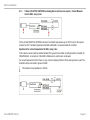
8.1 Analog Mode ................................................................................................................................................. 35
8.1.1 CSmicro SF15/ SF02/ M-3L/ M-3H as Analog Device (mV output on OUT) ............................... 35
8.1.2 CSmicro 2W as Analog Device (mA-two-wire-output) ................................................................. 36
8.1.3 CSmicro 2W-SF15H/ 2W-SF22H as Analog Device (mA two-wire-output) -
Current Measurement in GND- (Loop-) Line ................................................................................ 37
8.1.4 Maximum Loop Impedance (2W Models) .................................................................................... 38
8.2 Digital Mode ................................................................................................................................................... 39
8.3 Analog and Digital Mode Combined (2W) .................................................................................................... 40
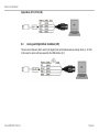
8.4 Direct Connection to an RS232 Interface on the Computer ......................................................................... 41
8.5 Alarm Output .................................................................................................................................................. 42
8.5.1 Open Collector Output (SF/ M-3) ................................................................................................. 42
8.5.2 Open-collector-Ausgang (2W)...................................................................................................... 42
9. Instructions for Operation ...................................................................................................................... 43
9.1 Cleaning ......................................................................................................................................................... 43
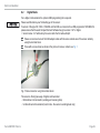
10. Software .................................................................................................................................................. 43
10.1 Installation ...................................................................................................................................................... 43
10.2 Minimum System Requirements ................................................................................................................... 44
10.3 Main Features ................................................................................................................................................ 44
10.4 Communication Settings ............................................................................................................................... 45
10.4.1 Serial Interface .............................................................................................................................. 45
10.4.2 Protocol ........................................................................................................................................ 45
10.4.3 Digital Command Set (Excerpt from the Document in the CD Directory \Commands) .............. 46
11. Basics of Infrared Thermometry ............................................................................................................ 48
12. Emissivity ................................................................................................................................................ 49
12.1 Definition ........................................................................................................................................................ 49
12.2 Determination of Unknown Emissivity ........................................................................................................... 49
12.3 Characteristic Emissivity ................................................................................................................................ 50
13. Warranty .................................................................................................................................................. 51

thermoMETER CSmicro
14. Service, Repair ....................................................................................................................................... 52
15. Decommissioning, Disposal .................................................................................................................. 52
Appendix
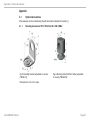
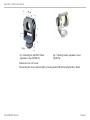
A 1 Optional Accessories ............................................................................................................................. 53
A 1.1 Mounting Accessories SF15/ SF02/ M-2/ M-3/ 2W/ 2WM-2 .......................................................................... 53
A 1.2 Mounting Accessories HS ............................................................................................................................. 55
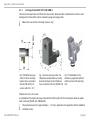
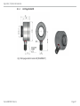
A 1.3 Air Purge Collars SF02/ SF15/ 2W/ 2WM-2 ................................................................................................... 56
A 1.4 Air Purge Collar HS ........................................................................................................................................ 57
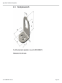
A 1.5 Right Angle Mirror ......................................................................................................................................... 58
A 1.6 USB Programming Adaptor ........................................................................................................................... 59
A 1.7 Tilt Assembly .................................................................................................................................................. 60
A 2 Factory Settings ...................................................................................................................................... 61
A 3 Emissivity Table Metals .......................................................................................................................... 64
A 4 Emissivity Table Non Metals .................................................................................................................. 67
A 5 Smart Averaging ..................................................................................................................................... 69
A 6 Direct Connection to an RS232 Interface .............................................................................................. 70

thermoMETER CSmicro

Page 7
Safety
thermoMETER CSmicro
1. Safety
The handling of the system assumes knowledge of the instruction manual.
1.1 Symbols Used
The following symbols are used in the instruction manual:
Indicates a hazardous situation which, if not avoided, may result in minor or mode-
rate injuries.
Indicates a situation which, if not avoided, may lead to property damage
Indicates a user action.
i
Indicates a user tip.
Measure
Indicates a hardware or a button/menu in the software
1.2 Warnings
Connect the power supply and the display/output device in accordance with the safety regulations for electri-
cal equipment.
> Danger of injury
> Damage to or destruction of the sensor and/or controller
Avoid shock and vibration to the sensor and the controller.
> Damage to or destruction of the sensor and/or controller
The power supply must not exceed the specified limits.
> Damage to or destruction of the sensor and/or controller
Protect the sensor cable against damage.
> Destruction of the sensor, failure of the measuring device

Page 8
Safety
thermoMETER CSmicro
Do not kink the sensor cable and bend the sensor cable in tight radius. The minimum bending radius is
14 mm (static). A dynamic movement is not allowed.
> Damage to the sensor cable, failure of the measuring device
No solvent-based cleaning agents may have an effect on the sensor (neither for the optics nor the housing)
> Damage to or destruction of the sensor
Avoid static electricity and keep away from very strong EMF (electromagnetic fields) e.g. arc welders or
induction heaters.
> Damage to or destruction of the sensor
Avoid changes of the operating temperature.
> Inaccurate measuring values
If sensors of the type CS / CSmi / CSmi2W und CsmiHS are connected to a USB-programmer TM-USBK-CS,
please ensure that the used CompactConnect Software has got a version 1.8.7 or higher.
> Version below 1.8.7 will destroy the sensor after the first write attempt!
1.3 Notes on CE Identification
The following applies to the thermoMETER CSmicro:
- EU-Directive 2014/30/EU
- EU-Directive 2011/65/EU, „RoHS”, category 9
Products which carry the CE mark satisfy the requirements of the quoted EU directives and the European
standards (EN) listed therein. The EC declaration of conformity is kept available according to EC regulation,
article 10 by the authorities responsible at
MICRO-EPSILON MESSTECHNIK
GmbH & Co. KG
Königbacher Straße 15
94496 Ortenburg / Germany
The system is designed for use in industry and laboratory and satisfies the requirements.

Page 9
Safety
thermoMETER CSmicro
1.4 Proper Use
- The thermoMETER CSmicro is designed for use in industrial and laboratory areas. It is used for non-con-
tact temperature measurement.
- The system may only be operated within the limits specified in the technical data, see Chap. 2..
- Use the system in such a way that in case of malfunctions or failure personnel or machinery are not endan-
gered.
- Take additional precautions for safety and damage prevention for safety-related applications.
1.5 Proper Environment
- Protection class:
Sensor: IP 65 (NEMA 4)
- Operating temperature:
Sensor: See also Chapter Measurement Specification, see Chap. 2.6
Controller (in cable): -20 ... 80 °C (-4 ... +176 °C) (all SF models)
-20 ... 75 °C (-4 ... +167)
1)
(all 2W models)
Avoid abrupt changes of the operating temperatures both of the sensor and the controller.
> Inaccurate measuring values
- Storage temperature: -40 ... 85 °C
- Humidity: 10 ... 95 %, non condensing
1) Or Vcc (supply voltage) 5 - 12 VDC/ at Vcc > 12 VDC the max. ambient temperature of the electronics is
65 °C.

Page 10
Technical Data
thermoMETER CSmicro
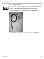
2. Technical Data
2.1 Functional Principle
The sensors of the thermoMETER CSmicro series are non-contact measuring infrared temperature sensors.
They calculate the surface temperature based on the emitted infrared energy of objects, see Chap. 11.
The sensor housing of the thermoMETER CSmicro is made from stainless steel (protection class IP 65), the
controller is integrated in the cable.
i
The thermoMETER CSmicro sensor is a sensitive optical system. Please only use the thread for
mechanical installation.
Avoid mechanical violence on the sensor.
> Destruction of the system

Page 11
Technical Data
thermoMETER CSmicro
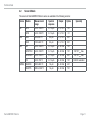
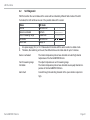
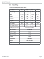
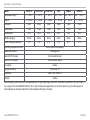
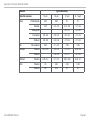
2.2 Sensor Models
The sensors of thermoMETER CSmicro series are available in the following versions:
Series Models Measurement
range
Spectral
response
Output Optics Speciality
SF SF15 -40 to 1030 °C 8 - 14 μm 0 - 5 / 10 V 15:1
SF02 -40 to 1030 °C 8 - 14 μm 0 - 5 / 10 V 2:1
M-3 M-3L 50 to 350 °C 2.3 μm 0 - 5 / 10 V 22:1
M-3H 100 to 600 °C 2.3 μm 0 - 5 / 10 V 33:1
2W 2W -40 to 1030 °C 8 - 14 μm 4 - 20 mA 15:1
2W-SF15H -40 to 1030 °C 8 - 14 μm 4 - 20 mA 15:1 180 °C T
amb
max.
2W-SF22H -40 to 1030 °C 8 - 14 μm 4 - 20 mA 22:1 180 °C T
amb
max.
HS -20 to 150 °C 8 - 14 μm 4 - 20 mA 15:1 0.025 K resolution
2WM-2 M-2SF40 250 to 800 °C 1.6 μm 4 - 20 mA 40:1
M-2SF75 385 to 1600 °C 1.6 μm 4 - 20 mA 75:1

Page 12
Technical Data
thermoMETER CSmicro
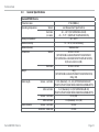
2.3 General Specifications
thermoMETER CSmicro
Protection class IP 65 (NEMA-4)
Operating temperature Sensor see Measurement Specifications
Controller
(in cable)
-20 ... 80 °C (SF15/SF02/M-3-L/M-3H)
-20 ... 75 °C
1)
(2W/2W-SF15H/2W-SF22H/HS)
Storage temperature -40 ... 85 °C
Relative humidity 10 ... 95 %, non condensing
Material (Sensor) Stainless steel
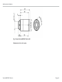
Dimensions Sensor 28 mm x 14 mm
(SF15/SF02/M-3-L/M-3H/2W/2W-SF15H/2W-SF22H/
(SF15/SF02/M-3-L/M-3H/2W/2W-SF15H/2W-SF22H/HS)
S)55 mm x 29,5 mm (HS)
Controller 35 mm x 12 mm
Weight 42 g
(SF15/SF02/M-3-L/M-3H/2W/2W-SF15H/2W-SF22H/HS)
200 g (HS)
Cable length Sensor - controller 0.5 m (Standard), 3 m, 6 m (SF15/SF02/M-3L/M-3H)
2
(2W-SF15/2W-SF15H/2W-SF22H/2WM-2SF40/2WM-2SF75)
After controller .5 m (Standard), 3 m (SF15/SF02/M-3L/M-3H)
(2W-SF15/2W-SF15H/2W-SF22H/2WM-2SF40/2WM-2SF75)
Sensor - controller 0.5 m (HS)
After controller 0.5 (Standard), 3 m (HS)
Cable diameter Sensor - controller 2.8 mm
Controller - cable end 4.3 mm

Page 13
Technical Data
thermoMETER CSmicro
thermoMETER CSmicro
Vibration IEC 60068-2-6 /-64: 3 G, 11 – 200 Hz, any axis
Shock IEC 60068-2-27: 25 G and 50 G, 11 ms, any axis
Pressure resistance (sensor) 8 bar
Software (optional) CompactConnect
1) For Vcc (power supply) 5 - 12 VDC/ at Vcc > 12 VDC the maximum operating temperature of the controller
is 65 °C
2) 6 m cable length not available for 3M version.
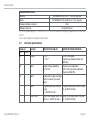
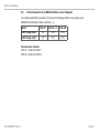
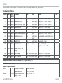
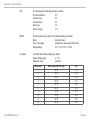
2.4 Electrical Specifications
Used pin Function SF02/SF15/M-3L/M-3H 2W/2W-SF15H/2W-SF22H/HS
OUT IN/ OUT
X Analog 0 - 5 V
1)
0 - 10 V
2)
4 - 20 mA/ scalable
(current loop between Power and
GND pin)
X Alarm Output voltage adjustable;
N/O or N/C
Output current adjustable;
N/O or N/C (current loop between
Power and GND Pin)
X Alarm 3-state alarm output (3 voltage
level for no alarm, pre-alarm,
alarm)
-
X Alarm Programmable open collector
output
(0 - 30 VDC/ 50 mA)
4)
Programmable open collector output
(0 - 30 VDC/ 500 mA)
X Temp. Code Temp.-Code Output (open col-
lector) (0 - 30 VDC/ 50 mA)
4)
Temp.-Code Output (open collector)
(0 - 30 VDC/ 500 mA)

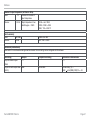
Page 14
Technical Data
thermoMETER CSmicro
Used pin Function SF02/SF15/M-3L/M-3H 2W/2W-SF15H/2W-SF22H/HS
OUT IN/ OUT
X Input Programmable functions:
- external emissivity adjust-
ment
- operating temperature
compensation
- triggered signal output and
peak hold function
5)
- Reset of hold function
6)
Programmable functions:
- triggered signal output and peak
hold function
5)
- Reset of hold function
7)
X X Serial digital
3)
uni- (burst mode) or bidirectional
Output impedances min.10kΩimpedance max.1kΩloopimpedance
Current draw 9 mA 4 - 20 mA
Power supply 5 ... 30 VDC
Status LED Green LED with programmable functions:
- alarm display (threshold independent from alarm outputs)
- Automatic aiming support
- Self diagnostics
- Temperature code indication
Vcc adjust mode - 10 adjustable emissivity and alarm values by variation of power
supply/ service mode for analog output (SF02/SF15 only)
1) 0 ... 4.6 V at power supply 5 VDC; also applies for alarm output
2)Onlyatpowersupply≥11V
3) Inverted RS232 signal, TTL, 9.6 kBaud
4) 500 mA if the mV output is not used
5) High level: > 0.8 V/Low level: < 0.8 V
6) Resetting peak or valley hold by high level on the IN/ OUT pin (low: open or GND / high: > 2.4 V ... 11 V)
7) Resetting of peak or valley hold by low level on the IN/ OUT pin (low: GND / high: open or > 1 V ... 11 V)

Page 15
Technical Data
thermoMETER CSmicro
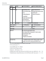
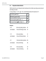
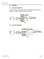
2.5 Pin Assignment
CSmicro
SF/M-3
white
yellow
green
brown
black
Power
OUT
IN/ OUT
GND
Shield
Power supply
Analog output/ TxD/ Alarm output
Analog input/ RxD/ Open collector output
Ground ( )
Shield
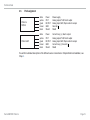
CSmicro2W
white
yellow
green
brown
black
Power
OUT
IN/ OUT
GND
Shield
Current loop (+)/ Alarm output
Analog output/ TxD/ Alarm output
Analog input/ RxD/ Open collector output
Current loop (-)/ Ground ( )
Shield
You will find a detailed description of the different sensor connections in Chapter Electrical Installation, see
Chap. 8.

Page 16
Technical Data
thermoMETER CSmicro
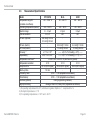
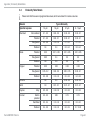
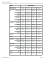
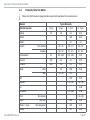
2.6 Measurement Specifications
Model SF15/SF02 M-3L M-3H
Temperature range IR
(scalable via software)
-40 ... 1030 °C 50 ... 350 °C 100 ... 600 °C
Operating temperature (sensor) -20 ... 120 °C -20 ... 85 °C -20 ... 85 °C
Spectral range 8 ... 14 μm 2.3 μm 2.3 μm
Optical resolution 15:1/ 2:1 22:1 33:1
CF lens (optional) 0.8 mm@ 10 mm/
2.5 mm@ 23 mm
- -
CF lens (built-in) - 5.0 mm@ 110 mm 3.4 mm@ 110 mm
CF1 lens (built-in) - 1.5 mm@ 30 mm 1.0 mm@ 30 mm
Accuracy
1)
±1 °C or 1 %
2)
------- ±(0.3 % T of reading
+ 2 °C) -------
Repeatability
1)
±0,5 °C or 0,5 %
2)
------- ±(0.1 % T of reading + 1 °C) -------
Temperature coefficient
3)
±0.05 K/ K or ±0.05 %/ K (whichever is greater)
Temperature resolution 0.1 K 0.1 K 0.1 K
Response time 30 ms (90 % signal) 25 ms (90 % signal) 25 ms (90 % signal)
Warm-up time 10 min - -
Emissivity/ Gain 0,100 ... 1,100 (adjustable via software)
Transmissivity 0,100 ... 1,100 (adjustable via software)
Interface (optional) USB (programming interface)
Signal processing Average, Peak hold, Valley hold (adjustable via software)
1) At operating temperature 23±5 °C, whichever is greater; Epsilon = 1; response time 1 s
2) At object temperatures > 0 °C
3) For operating temperatures < 18 °C and > 28 °C

Page 17
Technical Data
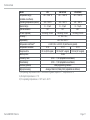
thermoMETER CSmicro
Model 2W 2W-SF15H 2W-SF22H
Temperature range
(scalable via software)
-40 ... 1030 °C -40 ... 1030 °C -40 ... 1030 °C
Operating temperature (sensor) -20 ... 120 °C -20 ... 180 °C -20 ... 180 °C
Specral range 8 ... 14 μm 8 ... 14 μm 8 ... 14 μm
Optical resolution 15:1 15:1 22:1
CF lens (optional) 0.8 mm@ 10 mm 0.8 mm@ 10 mm 0.6 mm@ 10 mm
Accuracy
1)
±1 °C or 1 %
2)
Repeatability
1)
±0.5 °C or 0.5 %
2)
Temperature coefficient
3)
±0.05 K/ K or ±0.05 %/ K (whichever is greater)
Temperature resolution 0.1 K 0.1 K 0.1 K
Response time 30 ms (90 % signal) 150 ms (90 % signal) 150 ms (90 % signal)
Warm-up time 10 min
Emissivity/ Gain 0,100 ... 1,100 (adjustable via software)
Transmissivity 0,100 ... 1,100 (adjustable via software)
Interface (optional) USB programming interface
Signal processing Average, Peak hold, Valley hold (adjustable via software)
1) At operating temperature 23±5 °C, whichever is greater; Epsilon = 1; response time 1 s
2) At object temperatures > 0 °C
3) For operating temperatures < 18 °C and > 28 °C

Page 18
Technical Data
thermoMETER CSmicro
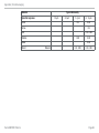
Model HS M-2SF40 M-2SF75
Temperature range
(scalable via software)
-20 ... 150 °C 250 ... 800 °C 385 ... 1600 °C
Operating temperature (sensor) -20 ... 75 °C -20 ... 125 °C -20 ... 125 °C
Spectral range 8 ... 14 μm 1.6 μm 1.6 μm
Optical resolution 15:1 40:1 75:1
Accuracy
1)
±1 °C o. ±1 %
3)
----- ±(0,3 % T of reading + 2 °C)
2)
-----
Repeatability
1)
±0,3 °C o. ±0,3 %
3)
----- ±(0,1 % T of reading + 1 °C)
2)
-----
Temperature coefficient
5)
±0.05 K/ K or ±0.05 %/ K (whichever is greater)
Temperature resolution 0.025 K
3)4)
0.1 K
4)
0.1 K
4)
Response time 150 ms (90 % signal) 10 ms (90 % signal) 10 ms (90 % signal)
Warm-up time 10 min - -
Emissivity/ Gain 0,100 ... 1,100 (adjustable via software)
Transmissivity 0,100 ... 1,100 (adjustable via software)
Interface (optional) USB programming interface
Signal processing Average, Peak hold, Valley hold (adjustable via software)
1) At operating temperature 23±5 °C; Epsilon = 1; response time 1 s
2) At object temperatures > 450 °C
3) At object temperatures > 20 °C
4) At time constants > 0.2 s
5) For operating temperatures < 18 °C and > 28 °C

Page 19
Delivery
thermoMETER CSmicro
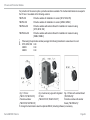
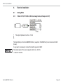
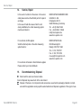
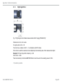
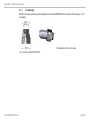
3. Delivery
3.1 Unpacking
1 thermoMETER CSmicro sensor including connection cable
1 Mounting nut
1 Instruction manual
1 isolated mounting bracket
1
Check the delivery for completeness and shipping damage immediately after unpacking.
In case of damage or missing parts, please contact the manufacturer or supplier.
You will find optional accessories in appendix, see Chap. A 1.
3.2 Storage
- Storage temperature: -40 ... 85 °C (-4 ... +185 °F)
- Humidity: 10 ... 95 %
1) Only supplied with the 2W-SF15H und 2W-SF22H sensor, see Chap. 8.1.3.

Page 20
Optical Charts
thermoMETER CSmicro
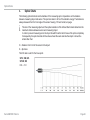
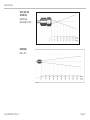
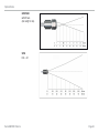
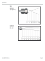
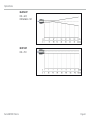
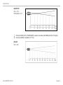
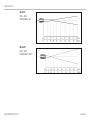
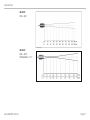
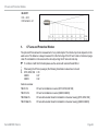
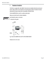
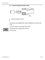
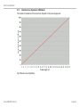
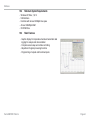
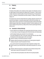
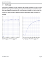
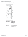
4. Optical Charts
The following optical charts show the diameter of the measuring spot in dependence on the distance
between measuring object and sensor. The spot size refers to 90 % of the radiation energy. The distance is
always measured from the front edge of the sensor housing / CF-lens holder/ air purge.
i
The size of the measuring object and the optical resolution of the infrared thermometer determine the
maximum distance between sensor and measuring object.
In order to prevent measuring errors the object should fill out the field of view of the optics completely.
Consequently, the spot should at all times have at least the same size like the object or should be
smaller than that.
D = Distance from front of the sensor to the object
S = Spot size
The D:S ratio is valid for the focus point.
SF15/ 2W/ 2W-
SF15H/ HS
D:S = 15:1
Page is loading ...
Page is loading ...
Page is loading ...
Page is loading ...
Page is loading ...
Page is loading ...
Page is loading ...
Page is loading ...
Page is loading ...
Page is loading ...
Page is loading ...
Page is loading ...
Page is loading ...
Page is loading ...
Page is loading ...
Page is loading ...
Page is loading ...
Page is loading ...
Page is loading ...
Page is loading ...
Page is loading ...
Page is loading ...
Page is loading ...
Page is loading ...
Page is loading ...
Page is loading ...
Page is loading ...
Page is loading ...
Page is loading ...
Page is loading ...
Page is loading ...
Page is loading ...
Page is loading ...
Page is loading ...
Page is loading ...
Page is loading ...
Page is loading ...
Page is loading ...
Page is loading ...
Page is loading ...
Page is loading ...
Page is loading ...
Page is loading ...
Page is loading ...
Page is loading ...
Page is loading ...
Page is loading ...
Page is loading ...
Page is loading ...
Page is loading ...
Page is loading ...
Page is loading ...
-
 1
1
-
 2
2
-
 3
3
-
 4
4
-
 5
5
-
 6
6
-
 7
7
-
 8
8
-
 9
9
-
 10
10
-
 11
11
-
 12
12
-
 13
13
-
 14
14
-
 15
15
-
 16
16
-
 17
17
-
 18
18
-
 19
19
-
 20
20
-
 21
21
-
 22
22
-
 23
23
-
 24
24
-
 25
25
-
 26
26
-
 27
27
-
 28
28
-
 29
29
-
 30
30
-
 31
31
-
 32
32
-
 33
33
-
 34
34
-
 35
35
-
 36
36
-
 37
37
-
 38
38
-
 39
39
-
 40
40
-
 41
41
-
 42
42
-
 43
43
-
 44
44
-
 45
45
-
 46
46
-
 47
47
-
 48
48
-
 49
49
-
 50
50
-
 51
51
-
 52
52
-
 53
53
-
 54
54
-
 55
55
-
 56
56
-
 57
57
-
 58
58
-
 59
59
-
 60
60
-
 61
61
-
 62
62
-
 63
63
-
 64
64
-
 65
65
-
 66
66
-
 67
67
-
 68
68
-
 69
69
-
 70
70
-
 71
71
-
 72
72


MICRO-EPSILON M-3H Owner's manual
- Category
- Measuring & layout tools
- Type
- Owner's manual
Ask a question and I''ll find the answer in the document
Finding information in a document is now easier with AI
Related papers
-
MICRO-EPSILON thermoMETER CS Assembly Instructions
-
-
 MICRO-EPSILON thermoMETER CX Owner's manual
-
-
 MICRO-EPSILON software Disc Thickness Variation Measurement Owner's manual
-
 MICRO-EPSILON thermoMETER CT Assembly Instructions
-
 MICRO-EPSILON thermoMETER CT Owner's manual
-
 MICRO-EPSILON thermoMETER CTM-4 Assembly Instructions
-
 MICRO-EPSILON Modbus RTU communication interface for CT and CTlaser Owner's manual
-
 MICRO-EPSILON Outdoor Protective Housing for thermoIMAGER TIM User manual


Other documents
-
Parallax SF02-AS Arduino Shield User guide
-
Traceable 2-in-1 Waterproof Food HACCP Thermometer User manual
-
-
-
-
optris CS Series User manual
-
-
Omega OS-MINI22-BRT User manual
-
Shinko IRT-300-AT, AS User manual
-