Page is loading ...

ELECTRO-VOICE
®
X
LC
i
TM
Rigging Manual
X
LC
i Rigging Manual

ELECTRO-VOICE
®
X
LC
i
TM
Rigging Manual1
Table of Contents
Rigging-Safety Warning.............................................................................................................................................. 2
0 Introduction.............................................................................................................................................................. 3
1 X
LC
i Rigging System................................................................................................................................................. 5
1.1 Overview of the X
LC
i Flying System.......................................................................................................... 5
1.2 Enclosure Rigging Hardware Details........................................................................................................ 5
2 X
LC
i Rigging and Flying Techniques ......................................................................................................................... 9
2.1 Array Considerations ............................................................................................................................... 9
2.2 Rigging an X
LC
i Array ............................................................................................................................... 9
2.3 X
LC
i Grid Installation and Assembly .........................................................................................................11
3 Rigging-Strength Ratings, Safety Factors, and Special Safety Considerations...................................................... 14
3.1 Working-Load Limit (WLL) and Safety Factor Definitions....................................................................... 14
3.2 Structural Rating Overview .................................................................................................................... 15
3.3 Simplified Structural-Rating Guidelines .................................................................................................. 15
3.4 Complex Structural-Rating Analysis ....................................................................................................... 17
3.5 Wind Loading......................................................................................................................................... 23
3.6 Electro-Voice Structural-Analysis Procedures........................................................................................ 24
4 Rigging Inspection and Precautions ...................................................................................................................... 25
References ............................................................................................................................................................... 27
Notes........................................................................................................................................................................ 28

ELECTRO-VOICE
®
X
LC
i
TM
Rigging Manual 2
Rigging-Safety Warning
This document details general rigging practices appropriate to the entertainment industry, as they
would apply to the rigging of Electro-Voice X
LC
i loudspeaker systems. It is intended to familiarize
the reader with standard rigging hardware and techniques for suspending X
LC
i loudspeaker
systems overhead. Only persons with the knowledge of proper hardware and safe rigging
techniques should attempt to suspend any sound systems overhead. Prior to suspending any
Electro-Voice X
LC
i loudspeaker systems overhead, it is essential that the user be familiar with the
strength ratings, rigging techniques and special safety considerations outlined in this manual. The
rigging techniques and practices recommended in this manual are, of necessity, in general terms
to accommodate the many variations in loudspeaker arrays and rigging configurations. As such,
the user is expressly responsible for the safety of all specific X
LC
i loudspeaker array designs and
rigging configurations as implemented in practice.
All the general rigging material contained in this manual is based on the best available
engineering information concerning materials and practices, as commonly recognized in the
United States, and is believed to be accurate at the time of the original printing. As such, the
information may not be directly applicable in other countries. Furthermore, the regulations and
requirements governing rigging hardware and practices may be superseded by local regulations.
It is the responsibility of the user to ensure that any Electro-Voice loudspeaker system is
suspended overhead in accordance with all current federal, state and local regulations.
All specific material concerning the strength ratings, rigging techniques and safety considerations
for the X
LC
i loudspeaker systems is based on the best available engineering information
concerning the use and limitations of the products. Electro-Voice continually engages in testing,
research and development of its loudspeaker products. As a result, the specifications are subject
to change without notice. It is the responsibility of the user to ensure that any Electro-Voice
loudspeaker system is suspended overhead in accordance with the strength ratings, rigging
techniques and safety considerations given in this document and any manual update notices. All
non-Electro-Voice associated hardware items necessary to rig a complete X
LC
i loudspeaker array
(grids, chain hoists, building or tower supports and miscellaneous mechanical components) are
the responsibility of others.
Electro-Voice
July, 2003

ELECTRO-VOICE
®
X
LC
i
TM
Rigging Manual3
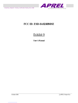
Figure 1a:
X
LC
i-127 Loudspeaker System
Front View (Without Grille)
Weight: 111 lb (50.4 kg)
Top View
14.25in
(362mm)
Center of Gravity
Side View
Rear View
Center of Gravity
8.31in
(211mm)
22.50in
(572mm)
18.75in
(476mm)
37.50in
(953mm)
C
L
11.02in
(280mm)
Cent.
0. Introduction
The X
LC
i (X-Line Compact Install) loudspeaker systems represent an important step in line-array
technology for small- and medium-scale sound reinforcement. The individual loudspeaker drivers,
acoustic lenses, acoustic waveguides, enclosures and rigging hardware were all designed
specifically for the X
LC
i product line to not only achieve the highest acoustic output with the highest
fidelity, but also to produce a precise wavefront from each element to achieve state-of-the-art line-
array performance. A brief description of the product line is included below. The X
LC
i loudspeaker
systems are shown in Figure 1 with key dimensions and weights.
X
LC
i-127: Three-way, LF/MB/HF loudspeaker system with a 120°H x 7.0°V coverage pattern. The
system includes one DL12ST 12-inch (305-mm) LF driver, two DM65 6.5-inch (165-mm) MB
drivers and two DH2T-16 2-inch (51-mm) HF drivers. The X
LC
i-127 has a switchable crossover that
allows either biamp or triamp operation. The X
LC
i-127 utilizes an enclosure that is trapezoidal in
the vertical plane (with an 8° total included angle) and has the standard X
LC
i 8° rigging plates
secured to the left and right enclosure sides.
X
LC
i-127+: Three-way, LF/MB/HF loudspeaker system with a 120°H x 7.0°V coverage pattern. The
system includes one DL12ST 12-inch (305-mm) LF driver, two DM65 6.5-inch (165-mm) MB
drivers and two ND6-16 3-inch (76-mm) HF drivers. The X
LC
i-127+ has a switchable crossover that
allows either biamp or triamp operation. The X
LC
i-127+ utilizes the same 8° trapezoidal enclosure
as the XLCi-127 and has the same standard X
LC
i 8° rigging plates secured to the left and right
enclosure sides.
X
LC
i-118: Subwoofer loudspeaker system with one EVX180B 18-inch (457-mm) woofer. The X
LC
i-
118 utilizes an enclosure that is trapezoidal in the vertical plane (with a 12° total included angle)
and has the standard X
LC
i 12° rigging plates secured to the left and right enclosure sides.
17.37in
(441mm)

ELECTRO-VOICE
®
X
LC
i
TM
Rigging Manual 4
Figure 1b:
X
LC
i-127+ Loudspeaker System
Front View (Without Grille)
Weight: 106 lb (48.1 kg)
Top View
Center of Gravity
Side View
Rear View
Center of Gravity
C
L
11.02in
(280mm)
Cent.
Figure 1c:
X
LC
i-118 Loudspeaker System
Front View (Without Grille)
Weight: 115 lb (52.2 kg)
Top View
21.44in
(545mm)
Center of Gravity
Side View
Rear View
16.64in
(423mm)
Cent.
9.38in
(238mm)
22.50in
(572mm)
18.75in
(476mm)
37.50in
(953mm)
C
L
Center of Gravity
14.25in
(362mm)
17.37in
(441mm)
7.94in
(202mm)
22.50in
(572mm)
18.75in
(476mm)
37.50in
(953mm)
24.90in
(633mm)

ELECTRO-VOICE
®
X
LC
i
TM
Rigging Manual5
1. X
LC
i Rigging System
1.1 Overview of the X
LC
i Flying System
The X
LC
i loudspeaker systems have been designed to construct acoustic line arrays. Acoustic line
arrays typically consist of independent columns of loudspeaker systems. This simplifies the
rigging system.
The X
LC
i loudspeaker enclosures utilize a hinged rigging system that makes constructing arrays
easy, predictable and repeatable. This front-hinging rigging concept allows arrays to be
constructed with the least possible spacing between enclosures. The front and back rigging
hardware for linking two enclosures together are captured as an integral part of the side rigging
frames.
A basic array is shown in Figure 2 that illustrates the integral components that make up a typical
X
LC
i flying system. The X
LC
i enclosures are vertically trapezoidal - taller at the front than at the
back. The enclosures are hinged at the front corners using rigging hardware specially designed
for the X
LC
i system. The enclosures are linked at the rear using rigging arms that have multiple
attachment positions. The different positions adjust how close the back corners of the enclosures
are pulled together; hence, adjusting the vertical angle of the bottom enclosure.
1.2 X
LC
i Enclosure Rigging Hardware Details
On each side of the enclosure there are two X
LC
i rigging plate assembies. The structural load is
transmitted through the plate minimizing the load on the loudspeaker enclosure shell. Figure 3
illustrates the X
LC
i enclosure rigging hardware components. Figures 4a and 4b show key
dimensions for the rigging hardware.
On the side of the enclosure towards the front is the Front Rigging Plate. The front rigging plate
has two threaded holes at the top and bottom for attaching the Front Connector Bar with the
included hardware. There is also a hole in the middle of the front rigging plate that accepts a
Rigging Handle. The rigging handles aid in positioning cabinets while assembling and flying an
array, and are intended for temporary use only.
The Front Connector Bar has 3 circular holes and one crescent shaped hole through it. The end
with two holes gets bolted to the top of the front rigging plate. The opposite end with the crescent
shaped recess is bolted to the front rigging plate of the cabinet above.
On the side of the enclosure towards the rear is the Rear Rigging Plate. There is a series of holes
at the bottom of the plate, and a single hole at the top. A Rear Connector Bar is bolted through the
top hole of the plate from an enclosure below and then bolted through one of the holes in the
pattern, linking the two cabinets together. The vertical tilt angle of the bottom enclosure is then
determined by the hole in which the rear connector bar is bolted through.
The X
LC
i-127 and X
LC
i-127+ enclosures may be angled from 0° to 8° in 1° increments, while the
X
LC
i-118 enclosure may be angled from 0° to 12° in 1° increments. The angle adjustment holes
are detailed in figures 4a and 4b. The bolts fix the distance the back corners of the enclosures
may be separated.

ELECTRO-VOICE
®
X
LC
i
TM
Rigging Manual 6
Figure 2:
Typical X
LC
i Flying System
Hoist Motor
X
LC
i Enclosures
Grid
Six X
LC
i Enclosures
Hinged at the Front by
the Front Connector
Bars and Front Rigging
Plates
Angles Between
Enclosures fixed by Bolts
through the Rear
Connector Bars and
Rigging Plates
Rear
Connector
Bar
Front
Connector
Bar

ELECTRO-VOICE
®
X
LC
i
TM
Rigging Manual7
Hole in Rear
Connector Bar to bolt
Rear Rigging Plate
from the Enclosure
above
Rear Rigging Plate
Rear Connector Bar
X
LC
Enclosure
Front Connector Bar
Front Rigging Plate
Figure 3:
X
LC
i Rigging Hardware
Holes in Rear Rigging
Plate to bolt the Rear
Connector Bar from the
Enclosure below
Holes in Front
Rigging Plate to bolt
the Front Connector
Bar from the
Enclosure below
Figure 4a:
X
LC
i-127 and X
LC
i-127+ Rigging Dimensions
Rear View
Side View
C
L
Front View (With Grille)
Hole Detail
Scale = 3:1
5.63in
(143mm)
Typ.
8.75in
(222mm)
1.00in
(25.4mm)
Typ.
37.50in
(953mm)
4.88in (124mm)
4.75in (121mm)
0.38in
(9.7mm)
R4.94in (125mm)
0.50in
(12.7mm)
Typ.
37.50in
(953mm)
0.50in
(12.7mm)
Typ.
Dia .385in
(9.8mm)
(9 Plcs.)
.730in (18.5mm) Typ.
.365in (9.3mm)
.300in (7.6mm)
20.90in
(531mm)
.730in (18.5mm) Typ.
0° Hole
1° Hole
2° Hole
3° Hole
4° Hole
5° Hole
6° Hole
7° Hole
8° Hole
Holes in Front
Connector Bar to bolt
Front Rigging Plate
from the Enclosure
above
Hole in Front Rigging
Plate for insertion of
Handle Bars to
assist in cabinet
positioning
Hole in Rear Rigging
Plate for insertion of
Handle Bars to
assist in cabinet
positioning

ELECTRO-VOICE
®
X
LC
i
TM
Rigging Manual 8
Figure 4b:
X
LC
i-118 Rigging Dimensions
Rear View
Side View
C
L
Front View (With Grille)
Hole Detail
Scale = 3:1
9.22in
(234mm)
Typ.
12.34in
(313mm)
1.00in
(25.4mm)
Typ.
37.50in
(953mm)
7.79in (198mm)
7.67in (195mm)
0.50in
(12.7mm)
R5.91in (150mm)
0.50in
(12.7mm)
Typ.
37.50in
(953mm)
0.50in
(12.7mm)
Typ.
Dia .385in
(9.8mm)
(13 Plcs.)
.737in (18.7mm) Typ.
.368in
(9.4mm)
.300in (7.6mm)
20.90in
(531mm)
.737in (18.7mm) Typ.
0° Hole
1° Hole
2° Hole
3° Hole
4° Hole
5° Hole
6° Hole
7° Hole
8° Hole
9° Hole
10° Hole
11° Hole
12° Hole

ELECTRO-VOICE
®
X
LC
i
TM
Rigging Manual9
2. X
LC
i Rigging and Flying Techniques
2.1 Array Considerations
The X
LC
i loudspeaker systems have been specifically designed to construct acoustic line-arrays.
Line-array systems typically consist of independent columns of loudspeaker enclosures. The most
common implementation would be a stereo sound reinforcement system with two columns (left
and right). Additional columns of loudspeakers are sometimes added to cover different seating
sections of a venue – seating areas that wrap around the side or back of a stage, for example.
The X
LC
i line arrays will consist of columns of X
LC
i-127 or X
LC
i-127+ 120°H x 7°V full-range
systems. The exact number of X
LC
i loudspeaker systems in a column will vary depending on the
vertical acoustic coverage required for the specific venue. Furthermore, the relative vertical angles
between the boxes will also depend on the venue’s acoustic coverage requirements. (Acoustic
design techniques are outside the scope of this document and the reader is directed to the X
LC
i
modeling software available from the Electro-Voice website for acoustic design assistance.) It is
also possible to construct subwoofer line arrays using the X
LC
i-118 systems.
Although the full-range X
LC
i loudspeaker systems shown in Figure 1 are not physically
symmetrical, their acoustical polar responses are substantially symmetrical because the high-
frequency sections are in the center of the enclosures. Thus, stereo left and right arrays, or left-
center-right arrays may be constructed with the loudspeakers in their normal right-side-up
orientation as shown in Figure1.
X
LC
i-127 AND X
LC
i-127+ LOUDSPEAKER SYSTEMS SHOULD NOT BE MIXED IN
THE SAME LINE-ARRAY COLUMN BECAUSE THEIR ACOUSTIC TIME AND
PHASE RESPONSE IS DIFFERENT. BOTH THE X
LC
i-127 AND X
LC
i-127+ HAVE
AN INTERNAL CROSSOVER THAT MAY BE SWITCHED IN OR OUT, ALLOWING
THE SYSTEMS TO BE TRIAMPED OR BIAMPED. TRIAMPED AND BIAMPED
SYSTEMS MUST NOT BE MIXED IN THE SAME LINE-ARRAY COLUMN
BECAUSE THEIR ACOUSTIC TIME AND PHASE RESPONSE IS DIFFERENT.
2.2 Rigging an X
LC
i Array
The X
LC
i loudspeaker systems utilize a rigid rigging system to suspend the enclosures. When
flying an X
LC
i system, it is recommended that the entire array be assembled in smaller clusters of
two or 3 cabinets rather than one large array.
WHEN ASSEMBLING TWO CABINETS TOGETHER, IT IS RECOMMENDED
THAT THE HARDWARE IS TIGHTENED FINGER TIGHT UNTIL BOTH CABINETS
ARE COMPLETELY LINKED.
First, attach the front and rear connector bars to the top of the front and rear rigging plates located
on the sides of the enclosure using the included hardware, as shown in Figure 5a. Using the
rigging handles, position the cabinet so that the front and rear rigging bolts can be attached to the
second enclosure. To make it easier for the front and rear rigging plates to be attached between
the two enclosures, the bolts and washers should initially only be finger tightened. Once all four
pieces of linking hardware are installed between the two enclosures, the hardware should be
tightened to a torque spec of 70-90 in-lbs (84-108 cm-kg).

ELECTRO-VOICE
®
X
LC
i
TM
Rigging Manual 10
ON EACH ENCLOSURE, ALWAYS MAKE SURE THAT THE LEFT AND RIGHT
REAR CONNECTOR BARS ARE BOLTED INTO THE SAME HOLE FOR THE
SAME VERTICAL SPLAY ANGLE.
MAKE SURE ALL LINKING HARDWARE IS TIGHTENED TO 70-90 IN LBS.
BEFORE ADDING ADDITIONAL ENCLOSURES TO THE ARRAY.
Attach the top enclosure in the array to the grid, as shown in Figure 5b. (Only an X
LC
i compatible
grid can be used with an X
LC
i array.) The front connector bars bolt through the bottom two holes
on the front of the grid sidearm, and the rear connector bar bolts through the top hole on the rear
of the grid sidearm.
MAKE SURE ALL LINKING HARDWARE IS TIGHTENED TO 70-90 IN LBS. AND
THE QUICK-RELEASE PINS ARE FULLY LOCKED INTO THE SPREADER BAR
BEFORE LIFTING THE ARRAY.
Begin to lift the grid and first cluster. Additional enclosures may be added one at a time, to the
bottom of the first cluster, or additional smaller clusters can be added to speed assembly time
using the previous steps. To disassemble the array, reverse the steps outlined in this section.
Figure 5a:
Flying X
LC
i Systems - Step 1
Install Finger Tight!
Split Washer (x2)
1.625 in (41.3mm)
long bolts
1.00 in (25.4mm)
long bolts

ELECTRO-VOICE
®
X
LC
i
TM
Rigging Manual11
Figure 5b:
Flying X
LC
i Systems - Step 2
Torque all bolts to 70-90 in-lbs.
(84-108 cm-kg)
Use handles as needed to
assist in cabinet positioning.
Choose hole according to X
LC
LAPS software program.
Split Washer
Nut
Split Washer (x2)
Washer
2.3 X
LC
i Grid Installation and Assembly
Assemble the sidearms to the enclosure rigging plates using the hardware shown to a torque spec
of 70-90 in-lbs (84-108 cm-kg) as shown in Figures 6a and 6b.
Figure 6a:
X
LC
i Grid Installation - Step 1
1.625 in (41.3mm)
long bolts
1.00 in (25.4mm)
long bolts
Sidearm
Enclosure

ELECTRO-VOICE
®
X
LC
i
TM
Rigging Manual 12
Figure 6b:
X
LC
i Grid Installation - Step 2
Once both sidearms are assembled, install spreader bar(s) between sidearms and lock into
numbered hole with attached quick-release pins as shown in Figure 6c.
Figure 6c:
X
LC
i Grid Installation - Step 3
Torque all bolts to 70-90 in-lbs.
(84-108 cm-kg)
Split Washer
Nut
Split Washer (x2)
Nut (x2)
1.625 in (41.3mm)
long bolts
1.625 in (41.3mm)
long bolts
Spreader Bar
Quick-Release
Pins

ELECTRO-VOICE
®
X
LC
i
TM
Rigging Manual13
Once spreader bar(s) have been assembled, lift grid and array using the pull-up points shown in
Figure 6d.
DO NOT LIFT GRID OVERHEAD USING SIDE HOLES ON SIDEARMS. ONLY
LIFT GRID FROM THE SUPPLIED SPREADER BARS.
Figure 6d:
X
LC
i Grid Installation - Fully
Assembled Configurations

ELECTRO-VOICE
®
X
LC
i
TM
Rigging Manual 14
3. Rigging-Strength Ratings, Safety Factors, and
Special Safety Considerations
3.1 Working-Load Limit and Safety Factor Definitions
The structural ratings for all of the X
LC
i rigging components and complete loudspeaker systems
are based on test results in which parts were stressed to failure. Manufacturers typically present
the structural-strength ratings of mechanical components or systems as either the working-load
limit (WLL) or the ultimate-break strength. Electro-Voice chooses to present the structural-load
ratings of the X
LC
i loudspeaker systems as the working-load limit. The working-load-limit rating
represents the maximum load that should ever be applied to a mechanical component or system.
THE USER SHOULD NEVER APPLY A LOAD THAT EXCEEDS THE WORKING-
LOAD LIMITS OF ANY OF THE RIGGING COMPONENTS OR COMPLETE
LOUDSPEAKER SYSTEMS DESCRIBED IN THIS MANUAL.
The working-load limits for the X
LC
i rigging components and complete loudspeaker systems
described in this manual are based on an 7:1 safety factor. The safety factor is defined as the
ratio of the ultimate-break strength divided by the working-load limit, where the ultimate-break
strength represents the force at which a part will structurally fail. For example, if a part has
working-load limit of 1,000 lb (454 kg), it would not structurally fail until a force of at least 7,000 lb
(3,629 kg) was applied, based on a 7:1 safety factor. However, the user should never apply a load
to that part that exceeds 1,000 lb (454 kg). The safety factor provides a margin of safety above
the working-load limit to accommodate normal dynamic loading and normal wear.
CAUTIONS for Working-Load Limits and Safety Factors
The working-load limits defined by the manufacturer of any rigging component should never be
exceeded. Electro-Voice bases the working-load limits of its X
LC
i products on an 7:1 safety factor.
Other manufacturers of rigging components may base their working-load limits on safety factors
other than 7:1. For example, 5:1 safety factors are fairly common amongst rigging manufacturers
because many regulatory agencies call for a minimum safety factor of 5:1.
When an X
LC
loudspeaker system is installed where local regulations only require a safety factor
of 5:1, Electro-Voice insists that the working-load limits of the X
LC
i rigging never be exceeded and
that an 7:1 safety factor be maintained for the X
LC
i loudspeakers.
The user is cautioned that some local regulations may require safety factors higher than 7:1. In
that circumstance, Electro-Voice insists that the user maintain the higher safety factor as required
by the local regulations throughout the entire X
LC
i installation. It is the responsibility of the user to
make sure that any X
LC
i installation meets any applicable local, state or federal safety regulations.

ELECTRO-VOICE
®
X
LC
i
TM
Rigging Manual15
3.2 Structural Rating Overview
There are two independent strength ratings that, together, give a complete description of the
overall structural performance capabilities of any X
LC
i loudspeaker system. They are defined as
follows:
1. The strength of each individual rigging point; which is the combined strength of the rigging
frame, the rigging frame components (front button bars, rear swing arm, quick-release pins, etc.)
and the enclosure.
2. The total strength of the overall enclosure; which is a function of the combined forces from
all of the rigging points acting on the rigging frames and enclosure as a whole.
The array designer must be aware of the working-load-limit ratings and the loads being applied to
the individual rigging points and the overall enclosure. An X
LC
i loudspeaker system is only as
strong as its weakest link. It is usually the case that one of the working-load limits will be ap-
proached sooner that the other.
WHEN SUSPENDING ANY X
LC
i LOUDSPEAKER SYSTEM OVERHEAD, THE
WORKING-LOAD LIMITS MUST NEVER BE EXCEEDED FOR EACH INDIVIDUAL
RIGGING POINT, OR THE OVERALL ENCLOSURE.
The forces acting on each individual rigging point and on the overall enclosures in an X
LC
i flying
system will vary with each array configuration. Determining the forces throughout an array re-
quires complex mathematical calculations. Electro-Voice engineers have, however, defined a set
of simplified structural-rating guidelines that eliminate the need for the complex calculations for
most array configurations. The interaction of the complex forces throughout arrays were analyzed
to develop this set of conservative guide-lines, presented below, to enable a rigger to immediately
determine on site whether or not an array is safe without having to make weight-distribution calcu-
lations. The structural-strength ratings of the individual rigging points and the overall X
LC
i enclo-
sures are also presented below so that a complex structural analysis can be made for any array
configuration. The reader should consult an experienced structural engineer to perform the com-
plex structural analysis.
The reader is directed to the References section of this manual for a list of rigging references (for
background in general rigging practice) and mechanical engineering references (for background in
structural engineering analysis).
3.3 Simplified Structural-Rating Guidelines
Electro-Voice engineers have defined a set of simplified structural-rating guidelines that will en-
able a rigger to immediately evaluate the safety of an X
LC
i system on site without having to make
complex force-distribution calculations. A combination of destructive testing and computer model-
ing were used to analyze the complex forces throughout arrays. Conservative working-load rat-
ings were utilized to simplify the guidelines. Therefore, array configurations other than those
illustrated in these simplified guidelines may be permissible for those applications, consult section
3.4 Complex Structural-Rating Analysis for a detailed structural analysis.
The simplified structural-rating guidelines are shown in Figure 7. (Note that there is a label on the
back of each flying X
LC
i loudspeaker enclosure that includes the graphics shown in Figure 7.)

ELECTRO-VOICE
®
X
LC
i
TM
Rigging Manual 16
These guidelines provide a simplified rating for typical arrays based on the:
1. Vertical angle of each enclosure
2. Total weight of that enclosure plus all of the enclosures and rigging hung below it.
3. Angles of the force components on the front connector bars and the rigging plates relative to
the enclosures.
4. Angles of the force components on the rear connector arms and rigging plates relative to the
enclosures.
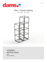
Figure 7:
Simplified X
LC
i Rigging-Rating Guidelines

ELECTRO-VOICE
®
X
LC
i
TM
Rigging Manual17
Figure 7 includes a graph of the working-load weight-versus-angle limit rating for the X
LC
i enclo-
sures. This working-load weight limit is applicable to every enclosure in an array, and includes the
weight of that enclosure plus the total weight of all enclosures and rigging hardware suspended
below it. The absolute enclosure angle is the vertical angle of that enclosure, where 0° represents
an upright enclosure facing straight ahead (0° elevation angle). These working-Ioad-versus-angle
limits take into account the complex forces generated in the front connector bars, the rear connec-
tor bars, the rigging plates, the enclosures and the (optional) pull-up line, as a result of the com-
plex weight distribution throughout the array.
Also included in the simplified structural-rating guidelines in Figure 7 are side-to-side and front-to-
back angle limits for the front connector bars and rear connector bars on the top enclosure.
WHEN APPLYING THE SIMPLIFIED STRUCTURAL RATING GUIDELINES TO
ANY X
LC
i LOUDSPEAKER SYSTEM SUSPENDED OVERHEAD, THE USER
MUST OBEY THE FOLLOWING RULES:
1. Never exceed the working-Ioad-versus-angle limit for any enclosure in the array.
2. Never exceed the side-to-side angle limits for the front connector bar assemblies on any
enclosure.
3. Never exceed the side-to-side angle limits for the rear connector bar assemblies on any
enclosure.
4. Always make sure that every front connector bar is securely bolted to the front rigging plate
on every enclosure (and grid, when applicable) before lifting overhead.
5. Always make sure that every rear connector bar is securely bolted to the rear rigging plate
with the supplied hardware on every enclosure (and grid, when applicable) before lifting
overhead.
6. If a pull-up grid is used, never exceed the side-to-side angle limits for the pull-up grid.
Discussion of Array Examples: For example, if the top enclosure in a column was angled down
30°, the enclosure working-Ioad-versus-angle limit from the simplified structural-rating guidelines
shown in Figure 7 would indicate that a total of 1820 pounds (885 kg) could be safely suspended.
This would include the weight of the top enclosure plus all of the enclosures and rigging sus-
pended below.
If, however, the top enclosure in a column was angled up 30°, the total allowable weight would
then only be 1220 lb (554 kg) - including the weight of the top enclosure plus all of the enclosures
and rigging suspended below. The enclosure working-load-versus-angle limit shown in Figure not
only applies to the top enclosure in an array column, but also applies to every enclosure in an
array column. In arrays where a pull-up grid is not used, the top enclosure is always the limiting
factor because it supports the most weight. However, in arrays where a pull-up grid is used to
achieve substantial downward angles, it is possible that a lower enclosure could be the limiting
factor.
3.4 Complex Structural-Rating Analysis
For a complete structural-rating analysis, the forces in each individual piece of attachment hard-
ware throughout the X
LC
i system must be determined, as well as the forces on each enclosure.
Determining these forces requires complex mathematical calculations. All of these forces must
then be compared to the working-load limits detailed below for each of the rigging points and the
overall enclosures.

ELECTRO-VOICE
®
X
LC
i
TM
Rigging Manual 18
The reader should consult an experienced structural engineer to perform the complex structural
analysis.
WHEN SUSPENDING ANY X
LC
i LOUDSPEAKER SYSTEM OVERHEAD, THE
WORKING-LOAD LIMITS MUST NEVER BE EXCEEDED FOR EACH INDIVIDUAL
RIGGING POINT, AND THE OVERALL ENCLOSURE.
X
LC
i-127, X
LC
i-127+ and X
LC
i-118 Front Rigging Structural-Strength Ratings
The working-load limit of each of the front rigging points on the X
LC
i enclosures is dependent upon
the front connector bar, bolts, front rigging plate, the enclosure and the angle of pull. The struc-
tural-strength ratings for the front rigging points are identical for the X
LC
i-127, X
LC
i-127+ and X
LC
i-
118, and are shown in Figure 8. The enclosures have two rigging points at the front. The structural
ratings shown in Figure 8 are for a single rigging attachment point. Each rigging point has the
same rating.
The front-to-back structural-strength ratings for the front rigging points shown in Figure 8 cover a
full 360° rotation. Although it is not possible to put the front connector bars into tension over 360°,
it is possible for the front connector bars to go into compression with some array configurations.
Therefore, the 360° rating is necessary to accommodate both tension and compression. It also
should be noted that the X
LC
front rigging is only rated for use over side-to-side pull angles of a
maximum of ±5°.
X
LC
i-127, X
LC
i-127+ and X
LC
i-118 Rear Rigging Structural-Strength Ratings
The working-load limit of each of the rear rigging points on the X
LC
i enclosures is dependent upon
the rear connector bar, bolts, rear rigging plate, the enclosure and the angle of pull. The structural-
strength ratings for the rear rigging points are identical for the X
LC
i-127 and X
LC
i-127+, and are
shown in Figure 9. The structural-strength ratings for the rear rigging points on the X
LC
i-118 are
shown in Figure 10. The enclosures have two rigging points at the rear. The structural ratings
shown in Figures 9 and 10 are for a single rigging attachment point. Each rigging point has the
same rating
It should be noted that the front-to-back-angle range shown in Figure 10 for the X
LC
i-127 and X
LC
i-
127+ consists of two 8° arc segments, while the front-to-back-angle range shown in Figure 11 for
the X
LC
i-118 consists of two 12° arc segments. When both the front and rear rigging are installed,
the front connector bar always prevents the rear connector bar from having any kind of front-to-
back force. Thus, it will always be axially loaded. For the X
LC
i-127 and X
LC
i-127+, a tensile force
can only be applied over an angle range of negative 0°-8°, while the X
LC
i-118 can only be over a
range of negative 0°-12°. The angles are negative because the boxes can only be angled
downward. (Imagine two boxes facing straight ahead. The bottom enclosure can only be tilted
downward because the rear rigging can only be adjusted to bring the rear corners of the
enclosures together.) Under compression, the forces would be from positive 172°-180° for the
X
LC
i-127,and X
LC
i-127+ and positive 168°-180° for the X
LC
i-118. It also should be noted that the
X
LC
i rear rigging is only rated for use over side-to-side pull angles of a maximum of ±5°.

ELECTRO-VOICE
®
X
LC
i
TM
Rigging Manual19
Figure 8:
X
LC
i-127, X
LC
i-127+ and X
LC
i-118 Front-Rigging-Point
Structural Ratings
-∅°
+∅°
-5°
MAX
+5°
MAX
0
100
200
300
400
500
600
700
800
900
1000
1100
-180 -150 -120 -90 -60 -30 0 30 60 90 120 150 180
Angle (Degrees)
Working-Load Limit (lb)
0
50
100
150
200
250
300
350
400
450
500
Working-Load Limit (kg)
/