Page is loading ...

d&b Flying System
User Manual

General information
d&b Flying System user manual
Version 2.0 E, July 1998
Order code D2903.E.02
Copyright by d&b audiotechnik AG 1995; all rights reserved.
The information presented in this document is, to the best of our knowledge, cor-
rect. We will however not be held responsible for the consequences of any errors
or ommissions.
Technical specifications, weights and dimensions should always be confirmed with
d&b audiotechnik AG before inclusion in any additional documentation.
In our efforts to develop and improve our products we reserve the right to
change the technical specification of our products without notice.
d&b audiotechnik tries, whenever possible, to minimise the effects of product
changes on equipment compatibility.
d&b audiotechnik AG
Eugen-Adolff-Straße 134, D-71522 Backnang, Germany
Telephone +49 / 7191 / 69 96 - 0, Fax +49 / 7191 / 95 00 00
Flying system - 2 Manual

Contents
Introduc tion . . . . . . . . . . . . . . . . . . . . . . 5
1. Flyin g safety . . . . . . . . . . . . . . . . . 6
2. The s ystem des ign . . . . . . . . . . . . . 8
2.1 Introduction and general description . . . . . . . . . . 8
2.2 Components . . . . . . . . . . . . . . . . . . . . . . . . 9
2.2.1 Sub bar . . . . . . . . . . . . . . . . . . . . . . . . . . . 9
2.2.2 Main bar . . . . . . . . . . . . . . . . . . . . . . . . . 10
2.2.3 Spreader bar . . . . . . . . . . . . . . . . . . . . . . 12
2.2.4 Studs, cabinet fixings, chains, straps and safeties . . . . 13
2.3 Accessories . . . . . . . . . . . . . . . . . . . . . . . . 14
3. Planning and constructing the array 15
3.1 General . . . . . . . . . . . . . . . . . . . . . . . . . 15
3.1.1 Planning . . . . . . . . . . . . . . . . . . . . . . . . . 15
3.1.2 Load limits . . . . . . . . . . . . . . . . . . . . . . . . 15
3.1.3 Hanging points, loading and motor hoists . . . . . . 15
3.2 Assembling the Flying System . . . . . . . . . . . . . 16
3.2.1 Unpacking, safety checks and system pre-alignment . . 16
3.2.2 Loading and cabling the array . . . . . . . . . . . . . 17
3.2.3 Strapping the array . . . . . . . . . . . . . . . . . . . 18
3.2.4 Final alignment of the array . . . . . . . . . . . . . . 18
3.2.5 Raising and securing the array . . . . . . . . . . . . . 18
3.3 De-rigging and dismantling the array . . . . . . . . . 19
3.4 Safety points and procedures . . . . . . . . . . . . . 20
4. B asic a rray configurations . . . . . . . . . . 2 2
5. Connecting and wiring 402 TOPs and SUBs
5.1 Example - P1200A
with one TOP and one SUB module fitted . . . . . . 33
5.2 Example - dedicated SUB controller
with one or two modules . . . . . . . . . . . . . . . . 33
6. C are and maintenan ce . . . . . . . . . . . . 35
(2.0 E) Flying system - 3

Appendices
Appendix 1 . . . . . . . . . . . . . . . . . . . . . . . . . . 40
Sub bar detent settings,
Spreader bar length and balance compensation
for 4 wide 402 systems
Appendix 2 . . . . . . . . . . . . . . . . . . . . . . . . . . 47
Setting the horizontal angle of the Sub bar
Appendix 3 . . . . . . . . . . . . . . . . . . . . . . . . . . 48
Setting the horizontal angle
between the Spreader bar and Main bars
Appendix 4 . . . . . . . . . . . . . . . . . . . . . . . . . . 49
Adjustable chains and the vertical angle
Appendix 5 . . . . . . . . . . . . . . . . . . . . . . . . . . 50
Calculating Spreader bar length for 402 arrays
Appendix 6 . . . . . . . . . . . . . . . . . . . . . . . . . . 51
Two wide flying bar, annual test & certification
Torque settings . . . . . . . . . . . . . . . . . . . . . . . . . . 53
Specifications . . . . . . . . . . . . . . . . . . . . . . . . . . 54
Flying system - 4 Manual

Introduction
The creation of a loudspeaker flying system which is safe, affordable
and easy to use is a far from simple task which confronts designers
with many engineering problems and conflicting demands.
The ideal flying system has yet to be built but would probably
incorporate the following key features :
– Light and easy to transport
– Takes up next to no truck space
– Simple and quick to set-up, load and fly
– Completely adjustable in every plane
– Easy to adjust - even when loaded
– All adjustments, angles etc. lock rigidly once set
– Can be used with any type or mix of cabinets
– Ultra high strength
– Ultra high load carrying ability
– Ultra high load safety factor
Although the ideal flying system is essentially an unattainable goal,
the practical value of the above design criteria is that they provide
a measure by which to judge the effectiveness of a given design
and so help to indicate directions for improvement.
The emergence of the 402 System as the prime d&b system for
concert applications created the need for an effective, well de-
signed flying system - a system which would allow clusters of
loudspeakers to be swiftly, safely and accurately arrayed in the
air.
The d&b Flying system for d&b 402, 702 and F2/B1 loudspeakers
described in this manual evolved from detailed investigations and
experiments into different ways of using bars, chains and straps to
fly multiple cabinet arrays. The resulting flying system was de-
signed and manufactured for d&b by UK specialists MAN Flying
Systems.
(2.0 E) Flying system - 5

1. Flying safety
The dominant concern in the design and use of flying systems is
safety - the safety of the public, performers and all those who
work with flying systems.
Confusion surrounds many of the safety issues connected with the
use of flying systems in places of public entertainment. Users are
frequently left to fend for themselves trying to find practical
answers to comply with the codes and legislation covering their
working activity.
Take for example the simple question - What is an acceptable
safety factor or margin for flying components above their certified
load rating? The answer depends upon the differing views of
safety authorities. In some states in the USA a load safety ratio of
2:1 is considered acceptable whilst in Germany, a load safety ratio
of 12:1 can be required. Needless-to-say, the d&b flying system
meets the more stringent German VBG70 recommendations.
As suppliers and manufacturers of safety critical equipment d&b
and MAN take seriously their responsibility to ensure the safety of
the systems they offer users. Care has been taken in the selection
of materials, manufacturing processes and design techniques to
ensure that the flying system components are conservatively load
rated so that the structural integrity, suitability and fitness of the
flying system design for its intended use is beyond reproach. After
manufacture flying system components are carefully inspected and
assembled for despatch to an independent test station. After com-
pletion of the external tests, including a load test at twice the
certified SWL, the systems then return to the MAN factory where
all safety critical components and assemblies are stamped or en-
graved and the manufacturers label attached.
Note that each production version of the flying system is sold as
a complete assembly and that each major component or sub-as-
sembly is traceable as being part of a specific, complete flying
system. Each system should always be treated as a complete sys-
tem and for safety’s sake components or sub assemblies should
never be swapped between systems.
Because of the diffusion of responsibility for safety which occurs
in practical situations there is simply no way that d&b, or indeed
any supplier of flying systems, can guarantee the complete safety
of flying equipment when it is used, or more pointedly - misused.
This manual does not constitute the definitive guide to good practice
in the use of flying systems but is intended to help promote safety
awareness by providing clear information on the capabilities, ad-
justment and safe use of the d&b flying system. In particular the
advice and information presented here does not absolve or excuse
users from meeting the legal safety requirements and codes in
force at the time and place where the equipment is deployed.
The rigging of loudspeaker flying systems in public or working
areas should only be undertaken by specialist contractors or mem-
bers of a site or touring crew with established, proven expertise
as riggers. Stage crew personnel assembling a system on site have
Flying system - 6 Manual

a duty to ensure the safe construction, adjustment and deployment
of the flying system.
The safety requirements demanded of flying system users vary
markedly from country to country and can even show great vari-
ation within a country or jurisdiction. It is thus beyond the scope
of this manual to fully inform operators of all aspects of the safe
use of the system in every conceivable situation, however, some
general points on site safety inspection procedures are worth
examining and commenting upon. At a public venue, users may
encounter a public safety officer acting on behalf of a local
licensing authority armed with the power and responsibility to
interpret the public health and safety legislation in force in that
locality. The rigour with which the statutes and codes of practice
governing public health and safety are applied or enforced de-
pends greatly upon the interpretation of a particular situation by
individual officials. The discretion of safety officers is often en-
hanced by the fact that the methods of risk assessment which they
employ are generally unpublished. In general, international tour
companies using flying systems report very few problems with
safety officials since the majority of those companies, to maintain
their reputation and business, employ trained staff, use profes-
sional equipment designed to a high specification and enforce their
own stringent safety practices.
It is common practice to divide or portion out responsibility for
safety on site, for instance, a distinction is frequently made with
rigging and flying systems between what occurs above hook (the
attachment point used to raise a system) and below hook. This
artificial divide often forms a satisfactory basis for good working
practice on site. But the compartmentalisation of safety is essen-
tially an artificial device which does not allow individuals to deny
or shirk their own responsibility. Recent examples of health and
safety legislation support the notion that responsibility for safety
is indivisible and have made it more difficult for an individual to
deny responsibility for safety in the workplace. The sobering con-
sequence of this is that behind the legislation and codes of practice
governing health and safety the final arbiter of the right and
wrong of the decisions and course of action taken or not taken by
an individual is a court of law.
As a final emphasis in this section on safety issues, both d&b and
MAN strongly encourage the provision of proper safety training
for personnel employed by companies to use the d&b flying sys-
tem. As a step towards improving knowledge of safe working
practices we recommend and urge the distribution of this document
to all users of the system. The contents of this manual must be read
and understood before using the system in any workplace or place
of public entertainment.
(2.0 E) Flying system - 7

2. The system design
2.1 Introduction and general description
Aware of the dangers to safety and user confidence of bad design,
MAN have created a flying system which not only complies with
the stringent 12:1 load safety factor recommended under VBG70
in Germany, but a system made safer by the removal of potential
sources of user frustration. The working principles of the system
are easy to understand and the possibility of un-intentional
misassembly has been designed out as far as possible.
The flying system allows arrays of d&b 402, 702 and F2/B1
cabinets to be vertically suspended or ’flown’ from a suitable point
in the roof structure of a theatre, hall, indoor arena or other place
of public entertainment. The d&b flying system is for use only with
the 402, 702 and F2/B1 loudspeaker systems and its use with any
other loudspeaker system is not allowed.
Each cabinet is fitted with D-ring style flying studs. Columns of
cabinets are then suspended daisy chain fashion from sub bars by
pairs of steel chains with safety hooks. A webbing strap threaded
through the rear of the cabinets gives stability and control of the
vertical angle of the column. Two columns are then attached side-
by-side to the underside of a Main bar suspended from the roof.
The horizontal angle of each loudspeaker column and the balance
of the Main bar are adjustable. Two or more Main bars can be
linked together at a set distance and horizontal angle by Spreader
bars.
A more detailed description of the system components follows.
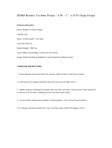
Spreader bar
Main bar
calibrated barrel adjuster
Sub bar
webbing strap
11 link chain
D-ring stud
Flying system - 8 Manual

2.2 Components
The d&b flying system consists of the following components: Sub bar,
Main bar, Spreader bar, studs, chains and webbing strap.
A basic two wide set-up consists of a Main bar, two Sub bars plus
the necessary accompanying chains, studs, straps and safeties to
allow two columns of 402/702 cabinets or F2/B1 cabinets to be
flown next to each other.
The next step-up uses two of the basic set-ups described above
linked together using a the third type of bar - the Spreader bar -
to create a four wide system. Two Main bars linked together with
the Spreader bar allow up to 24 402/702 or 16 F2/B1 cabinets
to be flown in a single cluster.
2.2.1 Sub bar
The Sub bar allows a single column of cabinets to be flown. The
bar is a square section steel tube with a steel strip welded beneath.
At each end of the bar are holes to accept safety hook chains and
in the middle a slot for a webbing strap plus a cable anchoring
point. The outer pair of holes are used for suspending a column
of 402/702 cabinets and the inner pair are to suspend a column
of F2/B1 cabinets.
For 402/702 cabinets, MAN flying studs are fitted to the sides of
each cabinet. The top cabinet is then hung from the outer Sub bar
suspension points using short, 11 link safety hook chains. The other
cabinets are then hung underneath the top one using 23 link safety
hook chains between each cabinet’s flying studs (see p.13). The
supplied webbing ratchet strap, employed as a load restraint, is
threaded through the slot in the centre of the Sub bar and then
through the ’kelping’ bars fitted at the back of each cabinet. On
tensioning the ratchet strap, the angle between the top and second
top cabinet in each column assumes a value of 4° and the angle
between each subsequent cabinet a value of 5°. As more tension
is applied to the ratchet strap, these angles between the cabinets
remain fixed and the whole column retains a fixed curved shape
as it starts to tilt downwards.
If the downward angle of the top cabinet in a column exceeds
–5°, then the webbing ratchet strap needn’t be threaded through
the upper kelping bar of the top cabinet. The maximum available
downward angle of the top cabinet when not using the top kelping
bar is approximately –15°. The strap should never be so highly
tensioned that the short chains from the Sub bar to the top cabinet
become loose and cease to be load bearing.
For columns of F2/B1 cabinets the inner Sub bar suspension points
and the 11 link safety hook chains are used for the first cabinet
WARNING!
(2.0 E) Flying system - 9

with pairs of longer 47 link safety hook chains for the remaining
cabinets. The angle between each cabinet is approximately 13°.
The Sub bar described above is supplied as part of a complete
flying system and should never be used on its own, without a
Main bar, to suspend cabinets. A special version of the Sub bar
with its own hanging adapter to fly a single column of cabinets is
available to order.
2.2.2 Main bar
Fabricated from steel box section, the Main bar has a detented
track with four captively mounted sliding blocks on its underside.
Pressing a spring loaded pushbar on each sliding block frees the
block to travel along the track - releasing the pushbar locks the
block into position on the track.
Two side-by-side columns of cabinets suspended from Sub bars can
be suspended underneath a Main bar. The outer pair of blocks
provide the load bearing connection between the Main bar and
each Sub bar via a ball-jointed pin.The inner pair of blocks connect
to the top of each Sub bar via a ball-jointed link pin with a built
in screw adjuster.
WARNING!
Flying system - 10 Manual

Deeper columns of cabinets and more extreme vertical angles
require greater horizontal separation between each column. This
is done by moving the outer blocks further apart towards each end
of the Main bar track.
Coarse setting of the horizontal angle between two columns of
cabinets is accomplished by altering the distance between the pair
of sliding blocks for each Sub bar. The screw adjuster on the Sub bar
link pin allows fine adjustment of the horizontal angle.
Also fitted to the Main bar is a calibrated balance adjuster to
compensate for uneven load distribution if different numbers and
types of cabinets are suspended from the Sub bars. A knurled
adjuster beneath the hanging point on top of the Main bar is
shifted along a screw track in the direction of the heavier load to
shift the balance block of the bar. Main bar balance adjustment
has to be carried out with the bar unloaded.
A shackle permanently attached via a ball-joined pin to the bal-
ance block provides the Main bar suspension point. The main pin
assembly incorporates a double hinge for attaching one or two
bars.
The free movement of the main pin in its socket helps protect it
against shearing forces but a badly balanced Main bar, more than
15° off balance, will force the neck of the pin against the bevelled
edge of the socket housing subjecting it to a dangerous shearing
force - never allow a Main bar to hang in a badly weighted
state. So that both balance adjustment scales in a 4 wide system
are visible from the same side there are two types of Main bar -
a left bar and a right bar.
Shackle
Suspension point hinge
Main pin
Balance block
Connector arm
Balance adjuster
Balance scale
WARNING!
(2.0 E) Flying system - 11

2.2.3 Spreader bar
The Spreader bar connects two Main bars at a defined distance
and horizontal angle. The exact distance apart depends on the
depth and geometry of the array and is set by adjusting the length
of the Spreader bar using the captive Tommy bar at its centre. To
aid adjustment each end of the Spreader bar has a scale cali-
brated in 2.5 cm increments from 140 cm to 185 cm - the distance
referred to is that between the hanging points.
Also at each end of the Spreader bar a machined slot and a
fastener bolt secured by captive pin allow it to be connected and
secured to the hinge fitted to the top of each Main bar.
The threaded section at each end of the Spreader bar has an
adjustable screw collar which connects to the balance block of
each Main bar via a floating link connector. It’s the position of the
collars on the threated section at each end of the Spreader bar
which defines the horizontal angle of each Main bars relative to
the Spreader bar.
As an aid to adjustment, calibrated scales from 0° to 60° in 5°
increments are set into each side of the threaded sections of the
Spreader bar. This mechanism for defining the horizontal angle has
the advantage that it is independent of the balance setting of the
Main bars.
Note: before fitting the Spreader bar link arm to the Main bar
connector arm, press the small spring loaded button (A) on the
connector arm. Excessive force should be avoided in order not to
break the spring load catch operated by the button.
When adding another Main bar and Spreader bar to an existing
four column wide system to create a six column wide system the
hanging point for the extra Main bar must be accurately
positioned - details are given with the later example of a six
wide system.
A
IMPORTANT!
Spreader bar link arm
Flying system - 12 Manual

2.2.4 Studs, cabinet fixings, straps,
chains and safeties
Built into the sides of each 402/702 cabinet and F2 & B1 cabinets
produced after 1993 are circular female stud plates which mate
with MAN D-ring flying studs - the studs are a key element of the
flying system design.
With the cabinet upright and the narrow part of the stud plate
keyhole to the top, fitting the studs is simple. The knob inside the
D-ring is pulled back to extend the locking stud which is then fitted
into the larger aperture of the keyhole, as the stud is pulled
upwards and the knob released the two components lock together.
To remove the D-ring the above fitting procedure is carried out in
reverse order.
The D-rings and stud plates provide the load bearing points for
attaching the loudspeakers to the flying system Sub bars. In the
case of the 402/702 cabinets, a pair of 11 link chains for the top
cabinet plus pairs of 23 link chains enables a column of cabinets
up to six deep to be suspended from each Sub bar.
The supplied 8 m webbing ratchet strap is used to link the cabinets
together and set the vertical angle or ’kelp’ of the column. The
strap is first of all threaded through the centre slot of the Sub bar,
through the ’kelping’ bars at the back of each cabinet before being
pulled tightly through the slot in the spindle of the ratchet mech-
anism and finally tensioned by cranking the ratchet handle. Above
a certain value the degree of tension applied alters the downward
tilt of the curved column. Please note that the webbing strap is
only intended to set and maintain the vertical curve and downward
angle of an array column and is not the principle load bearing
element of the design - that is the task of the chains.
Longer, adjustable chains can be supplied for use when a greater
vertical angle than the standard 5° angle between 402s/702s is
required. The length of the chains can be increased or decreased
in increments of 1.8 cm. The adjustable chains come in two types -
left and right. When using the chains viewed from FOH the chain
hook openings must all face to the front and the shortening device
must always be to the outside. To avoid impairing the acoustic
performance of the array, the angle between two vertically ad-
jacent 402 TOPs should never exceed 30°.
Although the load bearing capability of the flying system is over-
specified, for even greater safety an additional, secondary suspen-
sion should always be provided. Supplied with each Main bar are
a pair of steel wire safety ropes linked together at one end by a
steel O ring and terminated at their free ends with fixed shackles.
The shackles are attached to the safety lugs on top of the Main
bars whilst the O ring must be attached to a suitable, secure
overhead suspension point structurally independent of the main
rigging point(s) for the system. The wire safety ropes and their
shackles must always remain permanently attached to the Main
bars.
D ring flying stud and cabinet fixing
From left to right (above): 11 link
chain, 23 link chain, left shortening
chain, right shortening chain; (below):
ratchet strap
(2.0 E) Flying system - 13

2.3 Accessories
A flight case is available to transport a complete four wide system
of two Main bars, four Sub bars and a Spreader bar plus safeties
and speaker cable looms.
Deployment of the flying system is eased by the ability to wheel
the flight case beneath each hook point, open the case, attach a
Main bar and lift straight from the case using a motor hoist.
Correct use of the adjustable chains
Complete 2-wide system with steel wire safety ropes
Safety ropes
E7421 Touring case flying system 4 wide
Flying system - 14 Manual

3. Planning and constructing the array
3.1 General
3.1.1 Planning
A site survey should be conducted before arriving on site and a
rigging plan prepared. The rigging plan should include details of
the number and type of cabinets to be flown, their position in the
array as well as the angles needed to best cover the audience
areas of the venue. The tables in the appendices and the sample
configurations in section 4 can be used to derive the system set-
tings needed. The plan should also include the weight, intended
height and position of the load(s) to allow the venue riggers to
judge how best to attach the loaded flying system to the roof of
the building.
3.1.2 Load limits
If the full 12:1 safety margin of the flying system is required by
local safety regulations, then the roof or other structure, rigging
and the motorised chain hoists, should all be capable of supporting
loads 12 times that of a fully laden system.
The full specified load bearing capacity and safety margin of the
flying system is only available with the system and load suspended
vertically.
3.1.3 Hanging points, loading and motor hoists
The tables in section 4 allow users to determine the position of the
hanging points for different types of array set-ups. The chains or
steels suspended from the hanging points should hang vertically
with the array attached - if not, the load capability of the flying
system will be reduced by the horizontal shearing forces intro-
duced by misalignment. Because of this factor, we urge users to
take great care in ensuring the correct positioning and correct
relationship between hanging points.
Normally a 4 wide system is flown from two separate hanging
points it is however possible for arrays 3 to 4 cabinets deep to use
a bridle chain with the Spreader bar to hang the system from just
a single point. The load ratings of the motor hoist and the roof
fixing point will of course need to be doubled for single point
suspension.
The total weight of a flying system loaded with 12 402-TOPs
including rigging and safeties is approx. 800 kg. - therefore a
chain hoist motor with a minimum load capacity of 1t is recom-
mended. In calculating the total load for each hanging point re-
member to include the weight of the motor, cables and any extra
rigging - in any event it should be possible to keep the total load
on each point to under 1t.
(2.0 E) Flying system - 15

3.2 Assembling the Flying System
Assembly and deployment of a flying array can be carried out in
five stages :
– Unpacking, safety checks and
flying system pre-alignment
– Loading, strapping and cabling the array
– Kelping
– Checking the array alignment
– Raising and securing the array
Much physical strain and effort can be avoided through careful
pre-planning, by for instance ensuring that the cabinets are set out
in the correct order on the ground ready to construct the array
one row at a time. The chain motor hoists should be used to do
the heavy lifting - the Main bars in particular can be hooked to
their hoists straight from the flight case.
3.2.1 Unpacking, safety checks,
and system pre-alignment
The following description assumes that the above hook rigging has
been completed and that the chain hoist motors are in position
ready and waiting for a flight cased 4 wide flying system to be
wheeled in and attached.
There should of course be sufficient clear space beneath the rig-
ging points to unpack and set out the flying system.
Before commencing ensure that the motor hoist chains are not
twisted and that the motors hang straight and in the correct posi-
tion defined on the rigging plan. The chain bucket should be
behind the Main bar and the safeties to the front.
Before lifting the Main bars from the flight case the Main bar
balance should be set. The exact setting for each bar depends
upon the mix of cabinets being deployed - details are given in an
appendix. Note that this adjustment cannot be done with cabinets
already loaded onto the bars. Each Main bar can then in turn be
securely attached to the end of each motor hook and raised a
short distance into the air so that the safety inspection described
later in the care and maintenance section can be carried out
before pre-alignment of the system.
Pre-alignment involves pre-positioning the Sub bar sliding blocks
on the Main bar track to suit the size (depth) and coverage angle
of the loudspeaker array being loaded - suitable settings are
given with the standard configurations in section 4 and in the
tables in appendix 1. The distance between each pair of Sub bar
blocks on the Main bar track defines the coarse horizontal angle
between loudspeaker columns. Typically with 402 cabinets this
setting is 11 track detents visible between the blocks. The calibrated
barrel adjuster on the Sub to Main bar link connector can then be
used for the fine adjustment of horizontal angle.
The Spreader bar length can then be set (see the table in appendix
1). Ensure that the calibration marks at each end of the bar have
the same setting and that both the sliding latch clips face the front.
Flying system - 16 Manual

The adjustable screw collars each end of the spreader bar can be
set for the desired angle between the two Main bars.
3.2.2 Loading and cabling the array
The loudspeaker array is generally constructed two rows at a time.
The first two rows of cabinets are stacked in order on the ground
beneath the suspended Sub bars of the flying system - ensure that
TOP and SUB cabinets are in the order detailed in the array plan.
The top cabinet in each column is attached to its Sub bar using a
pair of D-rings and short, 11 link chains. D-rings and standard, 23
link chains are then used to connect the second row of cabinets to
the D-rings of the first row. Ensure that the open ends of all the
chain safety hooks face forward, clips closed with the chains free
of twists.
At this stage, with the first two rows of cabinets suspended just a
short distance above the ground, you should check and make any
necessary adjustments to the horizontal angles between the
speaker columns. Also at this stage, you should thread the ratchet
straps through the Sub bars and kelping bars of each speaker
column and attach the speaker multicore so that the cabinets can
be linked and connected as the array is constructed.
The system is then raised a short distance in the air to allow the
next two rows of cabinets to be wheeled beneath, tipped and
stacked. The system is then lowered with the first two rows resting
safely on top of the third and fourth rows. D-rings are then fitted
and used with standard chains to link the cabinets together. Again,
throughout the process ensure that the open ends of all the safety
hooks face forward, clips closed with the chains free of twists. As
rows of cabinets are added feed the ratchet straps through the
cabinet kelping bars and connect the speaker cables as you pro-
ceed. This process is repeated until all the rows of cabinets are
attached to the flying system.
With the final row of cabinets in place and the array raised a
short distance in the air, any errors in the pre-setting of the
horizontal balance of the flying bars should be obvious. Note that
a gross horizontal balance error can cause a Sub bar column to
flip backwards from a +15°setting to a -15° setting. Any necessary
adjustment to the horizontal balance of the bars is always carried
out with the array lowered and resting securely on the ground. For
four wide arrays as well as checking balance and angles, at this
stage any minor adjustments needed to the length of the spreader
bar due to inaccuracy in the planned positions of the rigging points
can be carried out.
A check should also be made to ensure that the chain hoist motors
operate correctly, running at the same speed so that the system
rises steadily, on the level and that the chains are not twisted and
feed unhindered into and out of the chain bucket. Ensure the chain
bucket is positioned so that it doesn’t touch the Sub bars.
CAUTION!
(2.0 E) Flying system - 17

3.2.3 Kelping the array
As previously indicated, whilst building the array the ratchet straps
are threaded through the Sub bars and cabinet kelping bars. Each
ratchet strap has the d&b logo printed on one side; to ensure the
correct orientation of the ratchet mechanism, the printing should
face you as the free end is fed through the Sub bar slot from
behind the array. As an array is constructed, the strap end is then
threaded through all the kelping bars on the rear of the column
starting with the top cabinet. Note though, that in some circum-
stances, for example when MAX cabinets are hung beneath a
column as downfills, the ratchet strap is not threaded through the
lower kelping bar of the final cabinet in the column. The standard
8 meter long ratchet strap is long enough to fit a six cabinet deep
402/702 array, although to finally thread the end of the strap into
the ratchet mechanism the bottom cabinet of the column may need
to be pulled back. Because of the limited capacity of the ratchet
mechanism, thread through as much of the strap as possible before
final tensioning. To allow later adjustment, the ratchet mechanism
is best positioned at the back of the second bottom cabinet. The
ratchet mechanism is then cranked to tension the ratchet strap, and
set the curve of each array column. Applying additional tension
sets the downward vertical angle of each column. Care should be
taken not to apply too much tension so that the top chains of the
column slacken and cease to be load bearing.
3.2.4 Final alignment of the array
Now is the time to carry out a visual check of the appearance and
alignment of the array. The proper balance of the array can be
judged by checking that the Sub bars lay parallel to the Main bar
and that both Main bars are aligned on the level.
An important point to note is that even with a properly balanced
Main bar adjacent array columns will not necessarily be perfectly
aligned in every direction. In particular, assuming that the top
cabinets of each column have the same downward angle, height
differences of some cm can be expected between columns. The
usual different mix of TOP and SUB cabinets in each column results
in different centres of gravity for the columns which cause the
differences in position. These slight differences in column position
have negligible impact on the acoustic performance of the array.
Note that this factor also means that you should not attempt to
judge how close to level the array is by looking for a neat line up
of cabinets at the bottom of the array.
Do not be tempted to try and correct these visual imperfections
by perhaps strapping adjacent columns together - this can’t be
done without affecting the Main bar balance.
3.2.5 Raising and securing the array
When all mechanical adjustments, system checks and safety checks
are completed the array can then be raised to its operating posi-
tion, locked off, and the steel safeties attached to the Main bars
secured to a separate, appropriately load rated rigging point in
the roof structure. Instruct the rigger attaching the safeties to be
Flying system - 18 Manual

careful not to disturb the balance or positioning of the array.
During the lifting operation watch out that the loudspeaker multi-
cores do not become entangled in the array - the cables can be
taped together as the system rises. Take care that both hoist motors
operate smoothly and lift at the same rate so that the system
remains stable and level as it travels.
3.3 De-rigging and dismantling the array
De-rigging and dismantling the array is essentially a reversal of
the procedure followed to construct and fly the system and the
same cautions and safety measures apply.
The safeties to the roof structure are first of all released. No one
should be present in the area beneath the array whilst it is lowered
in an even, smooth and controlled fashion.
The motors should be stopped when the array reaches a position
about half a meter from the ground and the kelping strap ratchets
released to allow the array columns to hang free vertically. Be
careful when releasing the ratchets as the sudden freeing of the
tensioned columns can be rather violent. The straps are then un-
threaded from the kelping bars of the bottom two rows of cabinets
and the cable loom of multicore tails and speaker link cables
unplugged and removed. The array is then carefully lowered to
the ground with the cabinets resting in a stable manner. The studs
and chains of the two bottom rows are then removed and the
remainder of the array carefully raised a short distance into the
air, the bottom two rows are then moved out of the way and the
same process repeated for the remaining rows of the array, two
at a time.
When packing the bars into their flightcase the Sub bars should
be positioned parallel to the Main bar and the outer sliding blocks
set to the 5th or 6th detent space from the ends of the Main bar
track. These settings are the default settings for arrays three or
four cabinets deep. Do not remove the steel safeties when packing
the system - these should always be attached ready for use.
3.4 Safety points and procedures
To ensure safety, the rigging of loudspeaker flying systems in public
or working areas should only be undertaken by specialist contrac-
tors or members of a venue or touring crew with established
proven expertise as riggers.
Personnel assembling a system on site have a duty to ensure the
safe construction, adjustment and deployment of the system. Be-
fore use all the system components must be subjected to careful
and rigorous inspection and any component or assembly which has
been misused or damaged must be rejected and replaced. If there
is any doubt what-so-ever about the safety and integrity of the
system then it must not be deployed.
The safety of the system is affected by the nature of the operating
environment in which it is deployed. If for instance it is deployed
out-of-doors during heavy rain, high winds or storms then inevit-
ably safety will be compromised.
CAUTION!
(2.0 E) Flying system - 19

All mechanical systems, flying systems included, eventually wear
out. The way the system is used, lack of maintenance, exposure to
water or corrosive agents, deformation or damage through im-
proper storage or transport will all accelerate the process of dete-
rioration and reduce the safety of the system. Owners and users
of the flying system must take all practical steps to protect the
system from deterioration.
The most important rule to follow when constructing and deploying
the system is to check, check and check again. Never assume or
take anything for granted - the most experienced and competent
system riggers can (and sometimes do) make mistakes so always
check your own work and that of the person next to you.
The chains are the load bearing supports for the suspended
cabinets; it’s important to use a short pair of chains (11 links) for
the first cabinet in each column to avoid transferring the load to
the kelping strap when the column is tilted.
For downward angles greater than the usual –5° (up to approxi-
mately –15°) the kelping strap should not be passed through the
very top kelping bar in the cabinet column. The strap however,
must be threaded through all the other kelping bars.
Always ensure that the chains are not twisted - all the safety hook
openings should face forward, clips closed. Finally, take care to
secure, dress and tidy the cable loom so that it doesn’t interfere
with the balance or free movement of the array.
It is very easy to plug in a Speakon connector so that it is not
properly locked, remember on fitting to twist the connector body
clockwise before turning the lock ring. Similarly, make sure that the
mating halves of the multipin speaker connectors are locked fully
together. It’s far easier and less hazardous to sort these things out
on the ground before the system is flown!
It helps in the case of larger arrays to have a work platform of
sufficient height available in order to avoid having someone clam-
ber over the swaying array to carry out adjustments. Please note
that it is not possible to adjust the balance of the Main bars with
the array suspended in the air - the array must be lowered to the
ground. The horizontal setting adjusters and ratchet strap tension
for the vertical setting can however be adjusted with the system a
short distance in the air.
Before flying the system, particularly with large arrays, it can save
time and frustration later on to have a crew member temporarily
wire up the controller racks and provide a test signal to check the
speaker wiring - when the check is complete, be sure to disconnect
the loudspeakers at the racks before raising the system.
During the set-up operation and especially during all lifting oper-
ations the safety of the work crew should be paramount. Site
safety rules must be clearly understood and observed by all. One
competent, experienced person should be in charge of operating
the hoists and should issue a clear loud warning, and be satisfied
that everyone is clear of the load before operating the hoists. An
observer should be stationed with a clear view of the flying system
as it rises in order to monitor and warn if it is not rising on the
level. For their safety, all site personnel not engaged in setting up
IMPORTANT!
Flying system - 20 Manual
/