Page is loading ...

BA00061S/04/en/14.11
Version 1.02.xx
71148182
Operating Instructions
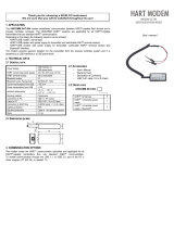
WirelessHART Adapter SWA70
Intelligent wireless modem
with power supply for field devices


WirelessHART Adapter SWA70 Table of Contents
Endress+Hauser 1
Table of Contents
Revision History............................... 3
Registered Trademarks ..........................3
1 Safety . . . . . . . . . . . . . . . . . . . . . . . . . . 4
1.1 Designated use . . . . . . . . . . . . . . . . . . . . . . . . . . . . 4
1.2 Installation, commissioning and operation . . . . . . . . 4
1.3 Operational safety . . . . . . . . . . . . . . . . . . . . . . . . . . 4
1.4 Conformance . . . . . . . . . . . . . . . . . . . . . . . . . . . . . 5
1.5 Radio approvals . . . . . . . . . . . . . . . . . . . . . . . . . . . . 5
1.6 Technical improvement . . . . . . . . . . . . . . . . . . . . . . 6
1.7 Conventions and icons . . . . . . . . . . . . . . . . . . . . . . 6
2 Identification . . . . . . . . . . . . . . . . . . . . 7
2.1 Unpacking . . . . . . . . . . . . . . . . . . . . . . . . . . . . . . . . 7
2.1.1 Visual inspection . . . . . . . . . . . . . . . . . . . . . 7
2.1.2 Scope of delivery . . . . . . . . . . . . . . . . . . . . . 7
2.1.3 Storage und transport . . . . . . . . . . . . . . . . . 7
2.2 Device designation . . . . . . . . . . . . . . . . . . . . . . . . . 8
2.3 Additional telecommunication compliances . . . . . . 10
2.4 Licensing agreement . . . . . . . . . . . . . . . . . . . . . . . 10
3 Function and System Design . . . . . . . 11
4 Mechanical Installation . . . . . . . . . . . 12
4.1 Getting started . . . . . . . . . . . . . . . . . . . . . . . . . . . 12
4.2 Mounting location . . . . . . . . . . . . . . . . . . . . . . . . . 12
4.3 Design . . . . . . . . . . . . . . . . . . . . . . . . . . . . . . . . . 13
4.4 Installation on a field device . . . . . . . . . . . . . . . . . 14
4.5 Separate mounting . . . . . . . . . . . . . . . . . . . . . . . . 15
4.5.1 Wall mounting . . . . . . . . . . . . . . . . . . . . . 15
4.5.2 Pipe mounting . . . . . . . . . . . . . . . . . . . . . . 16
4.6 Final check . . . . . . . . . . . . . . . . . . . . . . . . . . . . . . 17
5 Electrical Installation . . . . . . . . . . . . . 18
5.1 Wiring diagrams . . . . . . . . . . . . . . . . . . . . . . . . . . 18
5.1.1 Control loop without communication
resistor . . . . . . . . . . . . . . . . . . . . . . . . . . . 19
5.1.2 Control loop with communication resistor . 20
5.1.3 Two-wire device powered by adapter . . . . 21
5.1.4 Four-wire device . . . . . . . . . . . . . . . . . . . . 21
5.2 Wiring up . . . . . . . . . . . . . . . . . . . . . . . . . . . . . . . 22
5.2.1 Connecting cables and cable glands . . . . . . 22
5.2.2 Wiring procedure . . . . . . . . . . . . . . . . . . . 22
5.2.3 Electrical specification . . . . . . . . . . . . . . . . 23
5.3 Final check . . . . . . . . . . . . . . . . . . . . . . . . . . . . . . 23
6 Operation . . . . . . . . . . . . . . . . . . . . . 24
6.1 Operating and display elements . . . . . . . . . . . . . . . 24
6.1.1 Pushbutton . . . . . . . . . . . . . . . . . . . . . . . . 25
6.1.2 LEDs . . . . . . . . . . . . . . . . . . . . . . . . . . . . . 25
6.2 Local and remote operation . . . . . . . . . . . . . . . . . . 26
7 Commissioning . . . . . . . . . . . . . . . . . 27
7.1 Connected HART device(s) . . . . . . . . . . . . . . . . . . 27
7.2 Battery . . . . . . . . . . . . . . . . . . . . . . . . . . . . . . . . . 27
7.3 HART modem . . . . . . . . . . . . . . . . . . . . . . . . . . . . 28
7.4 DTMs and drivers . . . . . . . . . . . . . . . . . . . . . . . . . 29
7.4.1 Installing the Adapter DTM . . . . . . . . . . . . 29
7.4.2 Update the FieldCare DTM catalog . . . . . . 30
8 Configuration with FieldCare . . . . . . 31
8.1 Create a FieldCare Project . . . . . . . . . . . . . . . . . . . 31
8.1.1 Add the HART Communication
CommDTM . . . . . . . . . . . . . . . . . . . . . . . . 31
8.1.2 Configure the HART Communication
CommDTM . . . . . . . . . . . . . . . . . . . . . . . . 32
8.1.3 Scan for the adapter . . . . . . . . . . . . . . . . . . 33
8.1.4 Open the adapter DTM . . . . . . . . . . . . . . . 34
8.2 Online parameterization . . . . . . . . . . . . . . . . . . . . 35
8.2.1 Identification . . . . . . . . . . . . . . . . . . . . . . . 35
8.2.2 Wireless Communication . . . . . . . . . . . . . . 36
8.2.3 Wired Communication . . . . . . . . . . . . . . . 37
8.2.4 Device Variable Mapping . . . . . . . . . . . . . . 39
8.3 Application settings . . . . . . . . . . . . . . . . . . . . . . . . 40
8.3.1 4–20 mA . . . . . . . . . . . . . . . . . . . . . . . . . . 40
8.3.2 Burst Mode . . . . . . . . . . . . . . . . . . . . . . . . 42
8.3.3 Event Notification . . . . . . . . . . . . . . . . . . . 45
8.4 Power Supply . . . . . . . . . . . . . . . . . . . . . . . . . . . . 49
9 Additional DTM functions . . . . . . . . 51
9.1 Offline Parameterize . . . . . . . . . . . . . . . . . . . . . . . 51
9.2 Observe . . . . . . . . . . . . . . . . . . . . . . . . . . . . . . . . . 51
9.3 Diagnosis . . . . . . . . . . . . . . . . . . . . . . . . . . . . . . . . 52
9.3.1 Identification . . . . . . . . . . . . . . . . . . . . . . . 52
9.3.2 Wireless Communication . . . . . . . . . . . . . . 53
9.3.3 Wired Communication . . . . . . . . . . . . . . . 53
9.3.4 Health Status . . . . . . . . . . . . . . . . . . . . . . . 54
9.3.5 Battery . . . . . . . . . . . . . . . . . . . . . . . . . . . 55
9.4 Additional Functions . . . . . . . . . . . . . . . . . . . . . . . 56
9.4.1 Simulation . . . . . . . . . . . . . . . . . . . . . . . . . 56
9.4.2 Reset . . . . . . . . . . . . . . . . . . . . . . . . . . . . . 57
9.4.3 Lock/Unlock . . . . . . . . . . . . . . . . . . . . . . . 57
9.4.4 Update Firmware . . . . . . . . . . . . . . . . . . . . 58
9.4.5 Set DTM Addresses . . . . . . . . . . . . . . . . . . 58
9.4.6 Set Device Addresses . . . . . . . . . . . . . . . . . 59
9.4.7 Device DTM Info . . . . . . . . . . . . . . . . . . . . 59
9.4.8 Self Test . . . . . . . . . . . . . . . . . . . . . . . . . . 60
9.4.9 About . . . . . . . . . . . . . . . . . . . . . . . . . . . . 60
10 Maintenance and Repair . . . . . . . . . . 61
10.1 Battery unit . . . . . . . . . . . . . . . . . . . . . . . . . . . . . . 61
10.1.1 Exchanging the battery unit . . . . . . . . . . . . 61
10.1.2 Disposal of the battery unit . . . . . . . . . . . . 61
10.2 WirelessHART Adapter . . . . . . . . . . . . . . . . . . . . . 62
10.2.1 Return to Endress+Hauser. . . . . . . . . . . . . 62
10.2.2 Disposal . . . . . . . . . . . . . . . . . . . . . . . . . . . 62
10.2.3 Contact addresses . . . . . . . . . . . . . . . . . . . 62
10.3 Spare parts and accessories . . . . . . . . . . . . . . . . . . . 62

Index WirelessHART Adapter SWA70
2Endress+Hauser
11 Trouble-shooting . . . . . . . . . . . . . . . . 63
12 Technical Data . . . . . . . . . . . . . . . . . . 65
12.1 Input . . . . . . . . . . . . . . . . . . . . . . . . . . . . . . . . . . 65
12.2 Output . . . . . . . . . . . . . . . . . . . . . . . . . . . . . . . . . 65
12.3 Power Supply . . . . . . . . . . . . . . . . . . . . . . . . . . . . 66
12.4 Performance . . . . . . . . . . . . . . . . . . . . . . . . . . . . . 66
12.5 Environment . . . . . . . . . . . . . . . . . . . . . . . . . . . . 66
12.5.1 Battery deratings . . . . . . . . . . . . . . . . . . . 67
12.6 Mechanical Construction . . . . . . . . . . . . . . . . . . . 68
12.7 Operability . . . . . . . . . . . . . . . . . . . . . . . . . . . . . . 69
12.8 Certificates and Approvals . . . . . . . . . . . . . . . . . . 69
Index . . . . . . . . . . . . . . . . . . . . . . . . . . . . . . . . . . 72

WirelessHART Adapter SWA70
Endress+Hauser 3
Revision History
Registered Trademarks
HART®, WirelessHART®
Registered trademarks of the HART Communication Foundation, Austin, USA
Microsoft®, Windows®, Windows 2000®, Windows XP®, Windows 2003 Server®, Windows
Vista® and the Microsoft logo are registered trademarks of the Microsoft Corporation.
Acrobat Reader® is a registered trade mark of the Adobe Systems Incorporated.
All other brand and product names are trademarks or registered trademarks of the companies and
organisations in question
Product
version
Manual Changes Remarks
1.00.xx BA061S/04/en/03.09 – Original manual
1.01.xx BA061S/04/en/11.09 Chapter 5
Chapter 8.2.2
Chapter 11
Chapter 12
Update and addition of new connection diagrams
Join key now 8 character hexadecimal
Trouble-shooting updated
Technical Information:
Default HART address = 15, Battery tables added
1.02.xx BA061S/04/en/07.10 Chapter 8.3.2
Chapter 8.3.3
Chapter 9.4.2
Chapter 9.4.5
Chapter 9.4.6
General
New Burst overview page
New Event Notification overview page
New Reset function
New Set DTM Addresses function
New Set Device Addresses function
Updating of screenshots, small editorial changes
1.02.xx BA00061S/04/en/13.10 Chapter 2.2
Chapter 8.3.3
Chapter 12.6
Order Code: Approvals
Device Specific Event Mask: Byte 6, Bit 0
Fig. 12-1: Dimensions of Wireless Adapter SWA70
1.02.xx BA00061S/04/en/14.11 Chapter 1.3
Chapter 1.5, 12.5, 12.8
Chapter 2.2
Chapter 2.3
Chapter 4.5.1
Chapter 5.2.2
Hazardous areas
Additional wireless approvals added
Update, Fig. 2-1: Nameplate
New
Additional explanation of use of secondary cable entry,
Fig. 4-4, Fig. 4-5
Direct mounting, Indiret mounting

1Safety WirelessHART Adapter SWA70
4Endress+Hauser
1Safety
1.1 Designated use
Wireless Adapter SWA70 is an intelligent wireless modem designed for the transmission of
measured values from connected 4...20 mA or HART devices to a WirelessHART gateway. The
approved usage of the connected device(s) and gateway can be taken from the corresponding parts
of their operating instructions.
1.2 Installation, commissioning and operation
Wireless Adapter SWA70 has been designed to operate safely in accordance with current technical
safety and EU directives. Field devices connected to the adapter must also be designed to operate
safely in accordance with current technical safety and EU directives.
If devices are installed incorrectly or used for applications for which they are not intended, or if the
wireless adapter is not configured correctly, it is possible that dangers may arise. For this reason, the
system must be transported, stored, installed, connected, configured, operated and maintained
according to the instructions in this and the associated manuals: personnel must be authorised and
suitably qualified. This also applies to the handling of the adapter battery unit.
1.3 Operational safety
Location The Wireless Adapter SWA70 fulfils the requirements of EU Guidelines for a number of applications.
The associated environmental conditions described in Chapter 12, Technical Data, must be upheld.
Hazardous areas Wireless Adapter SWA70 is available in a version suitable for use in hazardous areas.
• The Non-Ex version must always be installed in a safe area
• Depending upon the approval, 2G Ex ia and/or 2D Ex tb, the Ex-version can be installed in a
gas or a dust hazardous location.
• The device(s) connected to the adapter must also be approved for use in hazardous areas
• Once a Wireless Adapter SWA70 has been used in a non-Ex installation, it should never be
used in an Ex installation, as there is a danger that the protective circuits have been
inadvertently overloaded and do no longer function correctly.
When installing components in explosion hazardous areas:
• Ensure that all installation and maintenance personnel are suitably qualified
• Check that all equipment has the appropriate safety certificates
• Observe the specifications in the device certificates as well as national and local regulations.
Batteries The Wireless Adapter SWA70 uses a battery unit containing non-rechargeable, high-power lithium
thionylchloride batteries. These batteries are non-hazardous when used according to the
recommendations of the manufacturer; they do, however, contain hazardous substances. Please
refer to the accompanying Material Safety Data Sheet when storing, handling, transporting and
disposing of the batteries (CD ROM folder Material Safety Data Sheet).
Maintenance The wireless adapter housing contains a single maintainable element, the battery unit. There are no
components which can be repaired by the user. In the event of a malfunction or defect, please return
the adapter, without batteries, together with the decontamination declaration at the end of the
manual to Endress+Hauser for repair, see Chapter 10.2.1.
#Warning!
• The adapter may be opened in a Dust-Ex hazardous area only when the measuring point is free
of dust and adequately ventilated.

WirelessHART Adapter SWA70 1Safety
Endress+Hauser 5
• Any tampering with the antenna, electronics or battery unit invalidates Endress+Hauser’s
warranty as well as the telecommunication compliance and any hazardous area approval.
The Ex-version may be opened in a gas hazardous area for battery exchange and commissioning.
1.4 Conformance
All declarations of conformity are to be found on the accompanying CD ROM in the folder
WirelessHART_Adapter/Certificates
CE Mark In attaching the CE Mark, Endress+Hauser confirms that Wireless Adapter SWA70 conforms to all
relevant EU directives. Declarations of conformity are available for both Ex and Non-Ex versions.
EMC All modules are suitable for industrial use and conform to the EU Electromagnetic Compatibility
Directive 2004/08/EG:
• Interference emission
EN 61326-1: 2006, Class B apparatus
• Interference immunity
EN 61326-1: 2006, Table 2 (industrial environment)
NE21
1.5 Radio approvals
#Warning!
• When the device is in operation, a distance of at least 20 cm must be maintained at all times
between the device antenna and the body of the user or any other person within the vicinity of
the measuring point irrespective of application or use
"Caution!
• Changes or modifications to the adapter not expressly approved by the Endress+Hauser will void
the user’s authority to operate the equipment.
FCC and IC compliance This device complies with part 15 of the FCC Rules. Operation is subject to the following two
conditions: (1) This device may not cause harmful interference, and (2) this device must accept any
interference received, including interference that may cause undesired operation.
R&TTE compliance This device complies with the requirements of the EC Telecommunications Directive 99/5/EG
• ETSI EN 300 328: V1.7.1 (2006-10)
• ETSI EN 301 489-17: V1.2.1 (2002-08)
• EN 60950: 2001
Chinese compliance This device has been granted a type approval by the SRRC (State Radio Regulatory Commission of
P. R. China): CMIIT ID 2011DJ5309
Japanese compliance This device has been granted a designation number by the Japanese Ministry of Internal Affairs and
Communications according to the Ordinance concerning Technical Regulations Conformity
Certification etc. of Specified Radio Equipment ( )
• Article 2 clause 1 item 19
• Approval n°: 202WW09117711
This device should not be modified (otherwise the granted designation number will be invalid).
R

1Safety WirelessHART Adapter SWA70
6Endress+Hauser
1.6 Technical improvement
Endress+Hauser reserves the right to make technical improvements to its software and equipment
at any time and without prior notification. Where such improvements have no effect on the
operation of the equipment, they are not documented. If the improvements affect operation, a new
version of the operating instructions is normally issued.
1.7 Conventions and icons
In order to highlight safety relevant or alternative operating procedures in the manual, the following
conventions have been used, each indicated by a corresponding icon in the margin.
Safety conventions .
Explosion protection .
Electrical symbols .
Icon Significance
Note!
A note highlights actions or procedures which, if not performed correctly, may indirectly affect operation or
may lead to an instrument response which is not planned
Caution!
Caution highlights actions or procedures which, if not performed correctly, may lead to personal injury or
incorrect functioning of the instrument
Warning!
A warning highlights actions or procedures which, if not performed correctly, will lead to personal injury, a
safety hazard or destruction of the instrument
Icon Significance
Device certified for use in explosion hazardous area
If the device has this symbol embossed on its name plate it can be installed in an explosion hazardous area
in accordance with the specifications in the certificate or in a safe area
Explosion hazardous area
Symbol used in drawings to indicate explosion hazardous areas. Devices located in and wiring entering
areas with the designation “explosion hazardous areas” must conform with the stated type of protection
Safe area (non-explosion hazardous area)
Symbol used in drawings to indicate, if necessary, non-explosion hazardous areas. Devices located in safe
areas still require a certificate if their outputs run into explosion hazardous areas
Icon Significance
Direct voltage
A terminal to which or from which a direct current or voltage may be applied or supplied
Alternating voltage
A terminal to which or from which an alternating (sine-wave) current or voltage may be applied or supplied
Grounded terminal
A grounded terminal, which as far as the operator is concerned, is already grounded by means of an earth
grounding system
Protective grounding (earth) terminal
A terminal which must be connected to earth ground prior to making any other connection to the
equipment
Equipotential connection (earth bonding)
A connection made to the plant grounding system which may be of type e.g. neutral star or equipotential
line according to national or company practice

WirelessHART Adapter SWA70 2 Identification
Endress+Hauser 7
2 Identification
2.1 Unpacking
2.1.1 Visual inspection
During unpacking:
• Check the packing materials for signs of transportation damage
• Remove the packaging material with care, so as not to damage the adapter
• Store the original packing material, in case the adapter must be shipped again
• Keep the documentation supplied with the adapter in a safe place
#Warning!
• If the battery unit is found to be damaged, proceed according to the Material Safety Data Sheet
on the CD ROM
• If the adapter is found to be damaged, it must not be commissioned and installed.
In the event of damage to the adapter, contact your Endress+Hauser Sales Center. Where possible,
return the adapter to us in its original packing.
2.1.2 Scope of delivery
Please check that the delivery is complete and free of defects before starting installation. The scope
of delivery comprises the following parts:
• WirelessHART Adapter with installed battery unit, if ordered
• Short instructions and CD-ROM
Depending on order:
• Wall/pipe mounting kit
• 38 cm cable for connecting the adapter to a field device.
• An connection adapter for connecting to the cable entry of a field device:
M20/M20 or M20/G 1/2 with two Viton gaskets, M20/NPT 1/2 or M20/NPT 3/4 with
one Viton gasket
• Cable gland
• FieldCare Device Setup DVD
• Folder with important documents like safety documentation
2.1.3 Storage und transport
Although the WirelessHART adapter is of robust construction, appropriate measures must be taken
to ensure correct storage and transportation:
Storage Condition Adapter w/o battery unit Adapter with battery unit battery unit alone
Temperature –40°C to +80°C/
–40°F to 176°F
Max. : <30°C/86°F
Recommended*: 21°C/70°F
Max. : <30°C/86°F
Recommended*: 21°C/70°F
Special precautions None Store with battery disconnected Store in a cool and ventilated
area, away from moisture,
sources of heat, open flames,
food and drink
*To minimize self-discharging a temperature a battery storage temperature <21°C/70°F is recommended

2 Identification WirelessHART Adapter SWA70
8Endress+Hauser
Transport When transporting the adapter take care that it is not subject to excessive vibration or shock.
#Warning!
• The battery unit is classed as Class 9 dangerous goods.
• If the adapter is to be shipped with battery unit to another site, the requirements in the Material
Safety Data Sheet must be observed.
2.2 Device designation
The device designation together with 1) Order number, 2) Serial number, 3) Telecommunication
compliance, is to be found on the nameplate affixed to the side of the module, see Fig. 2-1.
Fig. 2-1: Nameplate
Telecommunication compliance
(additional compliances on separate label, see Chapter 2.3)
Order Code Serial Number
Made in Germany, D- 79689 Maulburg
XA506F-X
-40°C Tamb +60°C≤≤
XXXXXXXXXXX
Ser.No.:
SWA70-I11A1A1+IKIWZ1
2010-02
NEMA4
0976
Dat.:

WirelessHART Adapter SWA70 2 Identification
Endress+Hauser 9
The device type can be derived from the order code as follows:
WirelessHART Adapter SWA70
Approvals
AA
BE
B1
CA
C1
I1
IE
Non-hazardous area
ATEX II 2 G Ex ia IIC T4
ATEX II 2G Ex ia IIC T4 Gb, ATEX II 2D Ex tb [ia] IIIC IP6x T70°C Db
CSA general purpose
CSA C/US IS Cl.I,II,III Div.1 Gp.A-G, NI Cl.I Div.2 AEx ia
IECEx Ex ia IIC T4 Gb, IECEx Ex tb [ia] IIIC T70°C Db
IECEx Ex ia IIC T4 Gb
Transmitter Interface
1
9
4-20 mA HART
Special version
Housing
A
B
Y
F32, Polyester IP66
F33, Aluminium IP66
Special version
Auxiliary Energy
1
5
9
Battery, built-in, lithium metal, transport class 9/2, UN3091
Prepared for battery
Special version
Version
A
B
C
Y
Prepared for installation on device
Prepared for installation separate from device
with wall/pipe mounting kit and M20 cable gland
Prepared for installation as router with wall/pipe mounting kit
Special version
Connection Adapter
1
2
3
4
8
9
Thread M20
Thread G 1/2
Thread NPT 1/2
Thread NPT 3/4
Without
Special version
Services
IK
IW
Customized configuration
Without tooling DVD (FieldCare Setup)
Marking
Z1 Tagging (TAG), see additional spec.
52006326: Wired on tag plate, stainless steel
52006327: Self-adhesive paper label
52006329: Supplier label/plate
SWA70- Product designation

2 Identification WirelessHART Adapter SWA70
10 Endress+Hauser
2.3 Additional telecommunication compliances
A sticker listing additional telecommunication compliances is to be found at the base of the antenna
as shown in Fig 2.2
Fig. 2-2: Position of sticker listing addtional telecommunication compliances
2.4 Licensing agreement
The CD-ROM supplied with the WirelessHART adapter contains a number of components that are
required for its commissioning. These can be installed free-of-charge on the computer to be used
with the adapter under the following operating systems:
• Microsoft Windows Vista Ultimate (32-bit)
• Microsoft Windows XP Service Pack 2 and 3 (32-bit)
Windows XP/Vista MUI Packages (multiple language support) are not supported. If another
language is required, the appropriate language version of Windows XP/Vista must be installed.
The full licensing agreement is also to be found on the CD-ROM. The software required for start-
up and commissioning, i.e. the Internet browser, is either freely available or is subject to the
licensing conditions of its manufacturer. Installation of this software on your computer implies that
you accept the terms of the corresponding licensing agreement.
R
202WW09117711
CMMIT ID 2011DJ5309

WirelessHART Adapter SWA70 3 Function and System Design
Endress+Hauser 11
3 Function and System Design
Wireless Adapter SWA70 Wireless Adapter SWA70 is an intelligent interface module that connects HART and 4...20 mA
devices to a WirelessHART network. It transmits the measurement and diagnosis information
acquired from the connected device to a host application via a WirelessHART Fieldgate.
The adapter is available in both a standard and Ex-version with aluminium or plastic housing. In the
latter case, the connected device must also have the appropriate Ex certification.
The adapter is battery powered. Where appropriate, the battery also provides loop-power to the
connected device. Alternatively, the connected device may be powered externally, see Chapter 5.
Fig. 3-1: WirelessHART network
WirelessHART network The WirelessHART network is self-organizing. After installation and configuration, every wireless
adapter is in a position to recognise its neighbours. Based on network identification and join keys
the adapter joins the network automatically. It checks the strength of their signals, receives
frequency, timing and path information and establishes connection with other participants in the
network without any intervention from the user.
Host applications
Ethernet
WirelessHART Fieldgate
Field devices with
Wireless Adapter SWA70

4 Mechanical Installation WirelessHART Adapter SWA70
12 Endress+Hauser
4 Mechanical Installation
4.1 Getting started
Wireless Adapter SWA70 can be mounted in one of three ways:
• direct connection to the field device
• separate from the field device, but connected by a cable
• when used as a repeater, as an autark unit.
The direct connection to a field device is made by means of an connection adapter which is screwed
into the cable entry at the side of the adapter.
Depending on the order, the following parts may be supplied:
• adapter for connection to a field device with a M20 cable entry
• adapter for connection to a field device with a G 1/2 cable entry
• adapter for connection to a field device with a NPT 1/2 cable entry
• adapter for connection to a field device with a NPT 3/4 cable entry
• M20 cable gland for separate mounting
• Wall/pipe mounting kit.
4.2 Mounting location
Wireless Adapter SWA70 is designed for stationary use in an unprotected location. More details on
environmental conditions can be found in Chapter 12, Technical Data.
In order to avoid unnecessary attenuation of the wireless signal with the resulting impairment of
operation, the following must be observed when mounting the adapter:, see also Fig. 4-1.
• The antenna must be at least 6 cm/2.5" away from any wall (1)
• The adapter must be mounted such that the antenna is not between it and a wall/post (2)
• The antenna must be at least 6 cm/2.5" from any metallic material running parallel to it (3).
• The antenna must always be aligned to the vertical (4).
Fig. 4-1: Things to be avoided when mounting
Wall 12
34
Wall
Pipe
<6 cm
<6 cm

WirelessHART Adapter SWA70 4 Mechanical Installation
Endress+Hauser 13
4.3 Design
A dimensional drawing is to be found in Chapter 12, Technical Data.
Fig. 4-2 shows the parts of the housing relevant to mounting.
Fig. 4-2: Lateral view of Wireless Adapter SWA70
The antenna (1) is mounted on the lefthand side of the housing. A counternut (2) is used to fix the
housing in position. The M20x1.5 cable entry (3) accepts the connection adapter (4), not shown,
from the field device, or in the case of separate mounting is closed by a blind plug. The secondary
M20x1.5 cable entry (5), normally closed by a blind plug, may be used for separate mounting. The
battery unit is contained within the housing, the cover of which (6) can be open by unscrewing the
four captive Phillips screws.
1 Antenna 4 Connection adapter (not shown), M20x 1.5
2 Counternut 5 Secondary cable entry for use when mounting
separately, M20x 1.5
3 Cable entry 6 Cover giving access to battery unit
1
2
3
4
5
6

4 Mechanical Installation WirelessHART Adapter SWA70
14 Endress+Hauser
4.4 Installation on a field device
You require the following tools to install the Wireless Adapter SWA70
• Metric wrench AF 24 (SW 24) for the connection adapter
• Metric wrench AF 42 (SW 42) for the counternut
Fig. 4-3: Installation on a field device
!Note!
• Loosening the counternut allows the connection adapter to be screwed into position without the
need to turn the adapter housing.
Procedure Mount the adapter directly on a field device as follows:
1 Remove the blind plug from the cable entry at the side of the adapter
2 Push a Viton gasket on either side of the connection adapter supplied with the adapter
3 Using a metric AF 24 wrench, screw the connection adapter tightly into the cable entry of the
field device (torque 5 Nm + 1 Nm)
4 Loosen the counternut on the adapter
5 Insert the other end of the connection adapter into the cable entry of the adapter and screw
tight using a metric AF 24 wrench (torque 5 Nm + 1 Nm)
6 Align the adapter so that the antenna is vertical
7 With the cable entry nut held with a wrench, tighten the counternut with a metric AF 42
wrench (torque 7 Nm).
1 Counternut 3 Connection adapter
2Cable entry
loosen
tighten
loosen
tighten
1
2
3

WirelessHART Adapter SWA70 4 Mechanical Installation
Endress+Hauser 15
4.5 Separate mounting
It is recommended that Wireless Adapter SWA70 be installed separate from a field device when:
• there is insufficient space at the measuring point to mount the adapter on the field device
• the signal reception at the measuring point is too weak for correct operation.
• the measuring point is subject to vibration above the permissible limits, see Chapter 11
The adapter can be mounted on a wall, post or other object, using the adapter wall/pipe mounting
kit, which is available as an accessory. The connection to the field device is made with standard
installation cable (and two cable glands). It is recommended that the blind plug be left in place until
the electrical connection is made.
4.5.1 Wall mounting
Mount on a wall as shown in Fig. 4-4.
Fig. 4-4: Separate mounting with mounting bracket
Depending on the type of mounting, in addition to the tools listed in Chapter 4.4, a M4 Allen key/
bit and metric wrench AF 8 may be required to tighten the mounting bracket screws.
Procedure 1 Mount the mounting bracket at a suitable position on the wall
2 Unscrew and remove the counternut
3 Thread the cable entry through the hole in the mounting bracket such that the antenna is on
the side farthest away from the wall
Mounting bracket
Blind plug
Secondary cable entry
with cable gland
for separate mounting

4 Mechanical Installation WirelessHART Adapter SWA70
16 Endress+Hauser
4 Remount the counternut and screw until the adapter is loosely held
5 Align the adapter so that the antenna is vertical
6 With the cable entry nut held with a wrench, tighten the counternut (torque 7 Nm).
7 Preferably use the secondary cable entry for the connection wire to the device.
4.5.2 Pipe mounting
Mount on a pipe of max. 70 mm diameter as shown in Fig.4-5.
Fig. 4-5: Installation on a pipe
In addition to the tools listed in Chapter 4.4, a M4 Allen key/bit and metric wrench AF 8 are
required to tighten the mounting bracket screws and a metric wrench AF 10 to tighten the pipe
mounting bracket.
Procedure 1 Mount the pipe mounting bracket at a suitable position on the pipe and screw tight
(torque min. 5 Nm)
2 Using the four screws supplied, screw the mounting bracket to the pipe mounting bracket
(torque 4 Nm + 1 Nm)
3 Now mount the adapter as described in Chapter 4.5.1.
Pipe mounting bracket
Pipe or post
max. 70 mm dia
Mounting bracket
Secondary cable entry
with cable gland
for separate mounting

WirelessHART Adapter SWA70 4 Mechanical Installation
Endress+Hauser 17
4.6 Final check
To complete the mechanical installation, check the following points:
• Has the adapter been damaged in any way during installation?
Damaged adapters should not be commissioned.
• Does the mounting location fulfil the environmental conditions for correct operation:
ambient temperature, relative humidity, vibration etc.?
• Is the antenna vertical?
• Does the position of mounting correspond to the requirements in Chapter 4.2?
• Is any mounting bracket correctly mounted and screwed tight?
• Are the connection adapter and counternut screwed tight?
• Is the secondary cable entry been used?

5 Electrical Installation WirelessHART Adapter SWA70
18 Endress+Hauser
5 Electrical Installation
5.1 Wiring diagrams
Device types The Wireless Adapter SWA70 can be connected to the following the device types/configurations:
• Field device operating in a control loop without communication resistor
• Field device operating in a control loop with communication resistor
– This configuration is used for HART multidrop with 2, 3 or 4 devices
• Two-wire field device operating independently with power supplied by the adapter
• Four-wire field device operating independently with power supplied by an external source
Fig. 5-1: Device types and configurations
Connection facilities The devices are connected to a 6-port terminal block located inside the adapter housing:
operating
independently
operating
in a control loop
Installation
without
communication resistor
Chapter 5.1.1
with
communication resistor
Chapter 5.1.2
2-wire
field device
Chapter 5.1.3
4-wire
field device
Chapter 5.1.4
Function Circuit Max. terminal voltage
Device supply
–
HART/4...20 mA Between Terminals 2 & 3
Ui 30 VDC
External Supply/
GND
HART high
impedance
–
HART high
impedance
Between Terminals 5 & 6
Ui 30 VDC
High impedance
GND
Rcom
2
1
3
4
5, 7
6, 8
+–
Power supply
Loop
current 1-2
Loop
current 2-3
Loop current
measurement
and HART
communication
HART
communication
/